To Model a RC residential structure using TSD
Q.1 Ans
Aim: Setup model for RC building design and based on following parameters for cover
| MEMBERS | IN CONTACT WITH GROUND | ABOVE GROUND |
| Column | 50mm | 40mm |
| Beam | 30mm |
25mm |
| Slab | 30mm |
25mm |
| Pilecap |
75mm |
|
|
Foundation |
50mm |
Introduction:
- The clear cover is the distance between the exposed concrete surface (without plaster and other finishes) to the nearest surface of the reinforcing bar look into the following image for more detail.
- As per IS 456 (Clause no. 26.4.1), the term clear cover is replaced by the term Nominal Cover. The nominal cover is the distance between the exposed concrete surface to nearest reinforcement bar (it may be any bar main bar, longitudinal bar even links and stirrups). The nominal cover should not be less than the diameter of the bar.
- Effective cover this term is usually used in design calculations. The effective cover is the distance between the exposed concrete surface to the centroid of the main reinforcement.
- The effective cover is the distance between the outermost compression face of RCC to the centre of the area of the main reinforcement in tension.
Procedure:
Step 1:
- Open the Tekla Structural Designer software and click on New to create a new file.
- Go to Home -> Settings -> Setting. In setting we can change the cover values.
- Go to Loading -> Structural defaults. Change the nominal cover values for the Beam, Column, Wall, Slab & pile caps.
- Select Construction levels default type as Structural Slab level (SSL). Change the values given in column of In contact with ground.

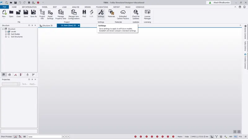
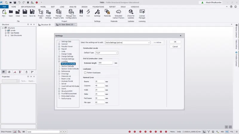
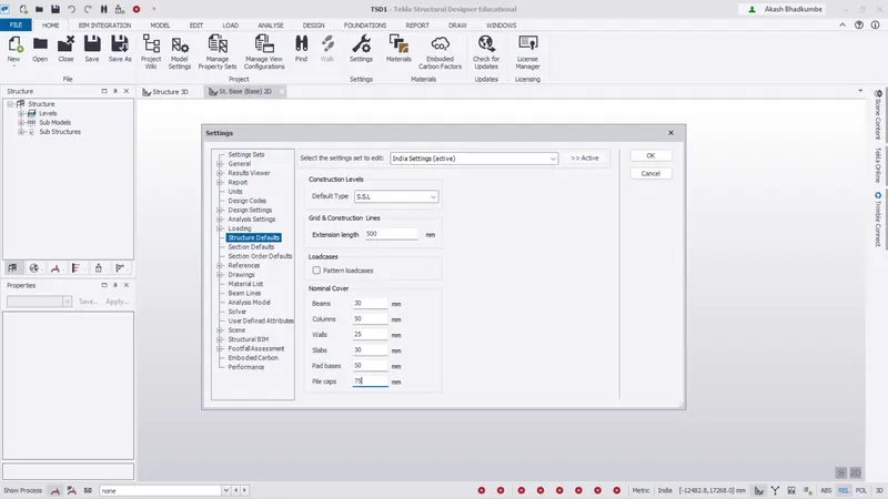
- Change the Construction level default type as Top of Foundation (TOF) and provide the values in column of Above ground.
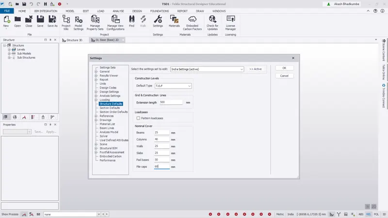
Conclusion:
- The cover for SSL & TOF is changed as given in the table.
Q.2 Ans
Aim: Model grid as per Attachment 2,2.1 & 2.2.
Introduction:
- Any of a series of numbered horizontal and perpendicular lines that divide a map into squares to form a grid means of which any point may be located by a system of rectangular coordinates.
- Grid Lines that cross the chart plot to show axis devisions. Grid lines helps viewers of the chart see what value is represented by an unlabeled data point.
Procedure:
Step 1:
- Open the project. To add grid lines go to the Model tab.
- Go to Model -> Grid & construction lines -> Grid lines.
- Click on grid line and draw a vertical or horizontal line with random distance.
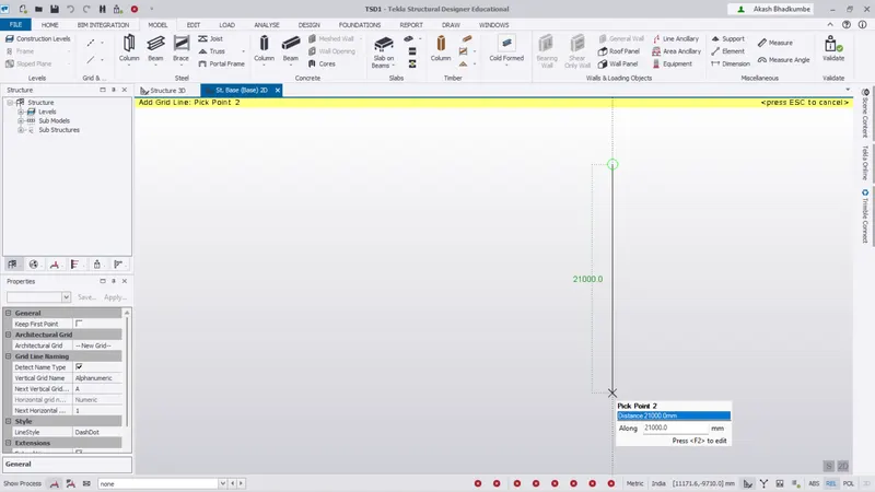
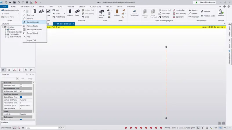
- To quick draw grids use Parallel (Quick option) in grid line and click on previous line.
- Press F2 and edit the distance value from previous grid line and give new distance and click on right or left side.
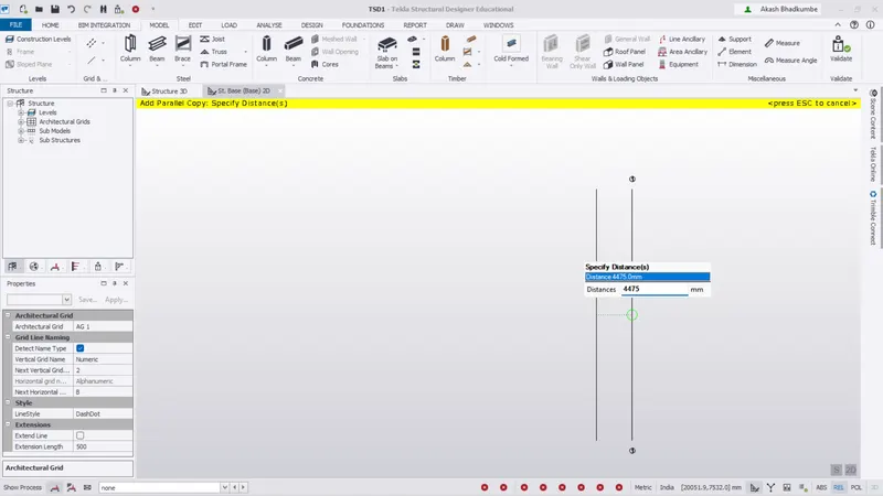
- Similarly draw all the vertical grids.
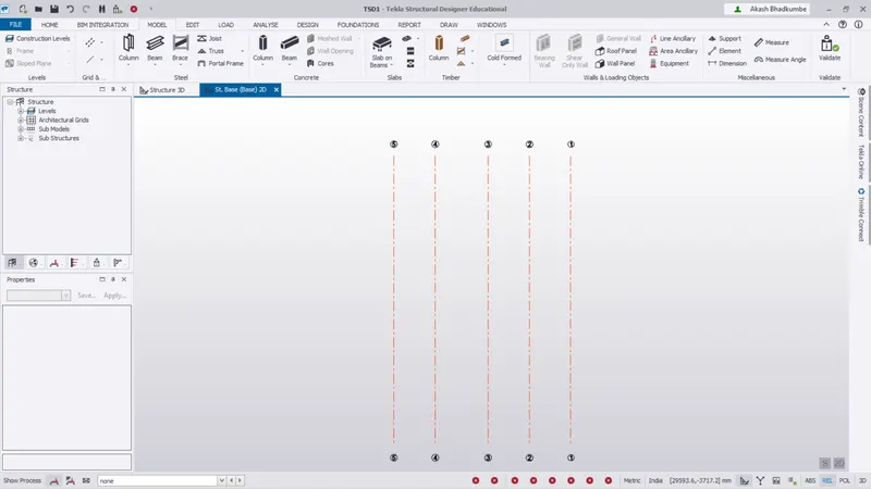
- To draw horizontal grid use perpendicular grid option.
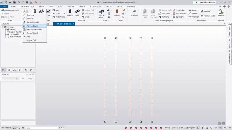
- Click on perpendicular grid and click on any of the vertical line and draw horizontal grid.
- Change the lebel of grids from properties browser as numerical or alphabetical.
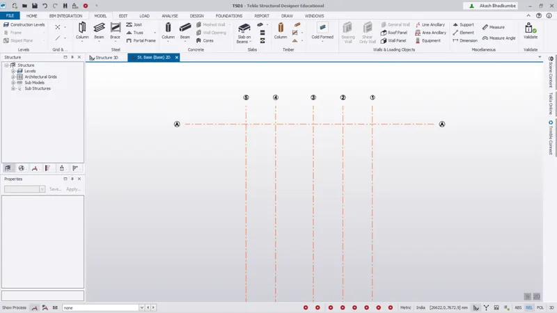
- Use the parallel quick option draw the remaining grid lines with proper distance.
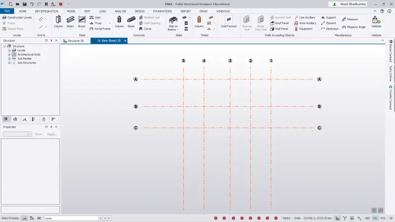
Conclusion:
- All grids are drawn as per the given attachement 2,2.1 & 2.2.
Q.3 Ans
Aim: Study the layout and write a summary for general arrangement of the structure.
Introduction:
- Columns should be places nearby the corners of the building, and at the points where beams and walls come together. Select the location of columns so that beams don't bend. Avoid beams that are too long. Avoid columns between lot of space between them.
- There are some basic rules for where columns should be placed. Columns are important because they carry the weight of the structure, so they need to be strong and stable. It is important to ensure that they are aligned vertically so that the weight is properly transferred to them.
Procedue:
Step 1:
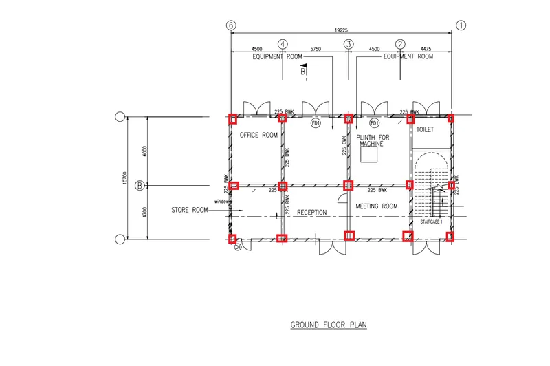
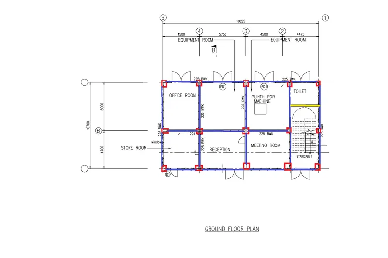
- According to some basic rules we are placing the columns at the corner of the building.
- Placing the column with less distance between one column to other.
- Check that the door and windows are not clash with the column.
- Red colour marking shows the location of column on existing plan.
- Blue colour represents the main beam and yellow colour represents the intermediate or secondary beams.
Conclusion:
- The arrangement of beam and column is done as per basic guidelines.
Q.4 Ans
Aim: Model RC columns, beams and slabs as per your general arrangement.
Procedure:
Step 1: Placing of columns.
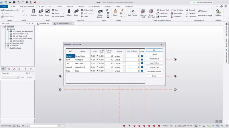
- Define construction levels for the RC office building.
- To define construction level Go to Model -> Levels -> Construction Levels.
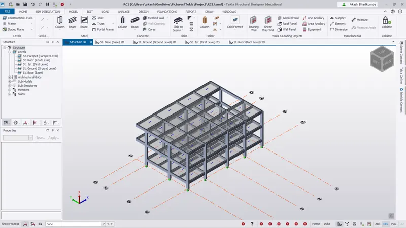
- The given structure is G+1 structure. Includes Base level, Ground Level, First Level, Roof level & Parapet.
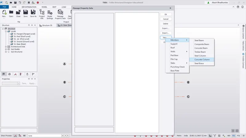
- Define section properties for column. Go to Model -> Manage Property set.
- In Manage Property set -> New -> Member -> Concrete Column.
- Add new property for column and name it as C1. Change the parameters as given below.
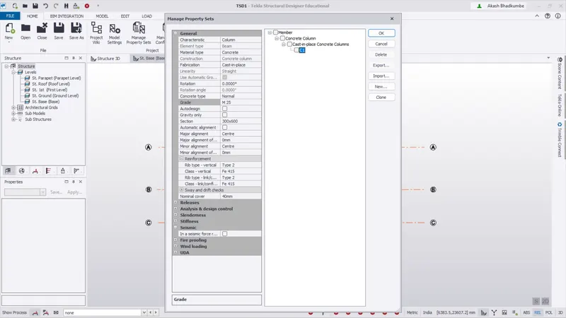
- Go to Model -> Concrete -> Column. Select the column property as C1.
- Place the columns at the intersection of grid.
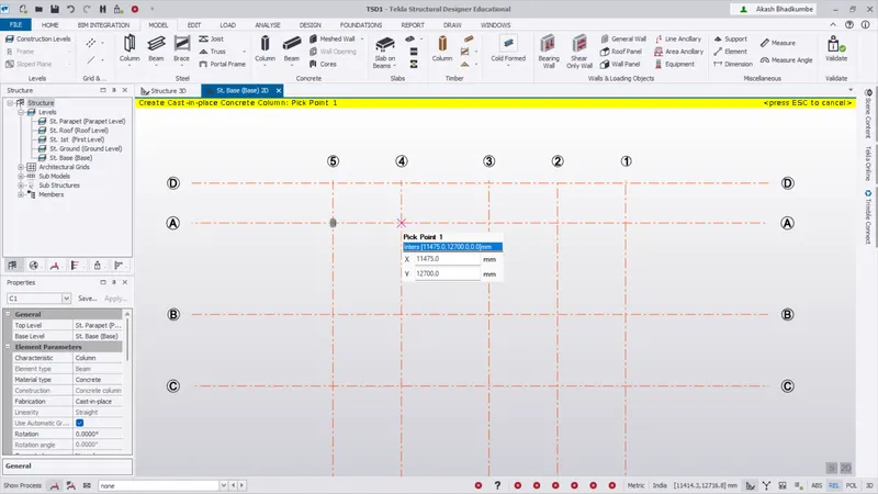
- All columns are added at the intersection and where requires as per building plan.
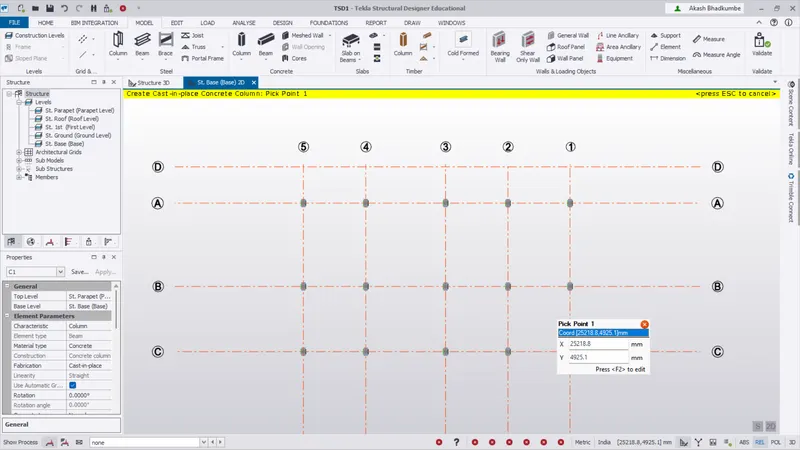
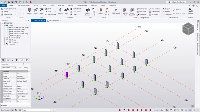
Step 2: Placing of beam.
- Deefine the properties of beam.Go to Model Property set.
- Model Property set -> New -> Member -> Concrete Beam.
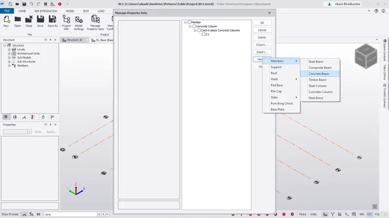
- Create property set for Primary and secondary beams.
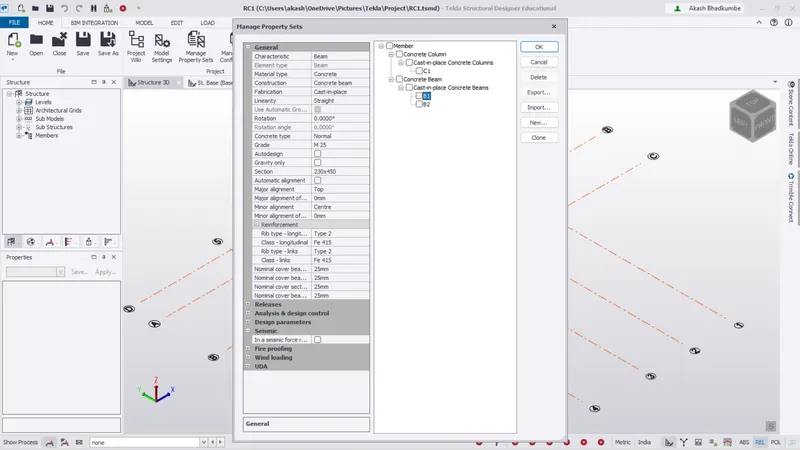
- Go to Model -> Concrete -> Beams. Select the Primary and secondary beams and add the beams.
- Carefully provide the beam from one column to another and click on validate.
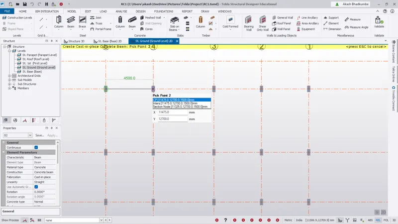
- Add all the primary and secondary beams where required.
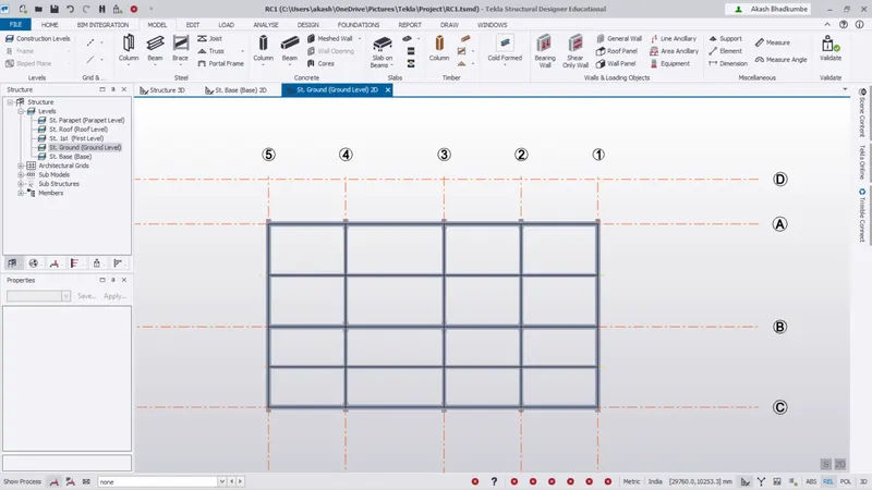
- The beams at ground level.
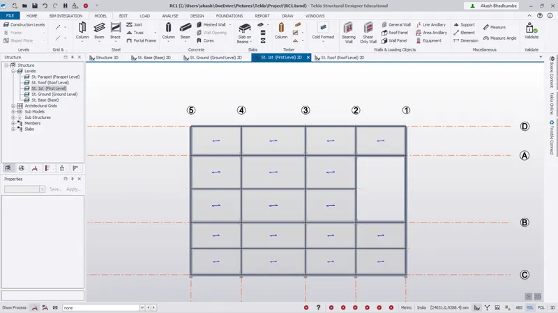
- Create beams at First And Roof level and leave the staircase area.
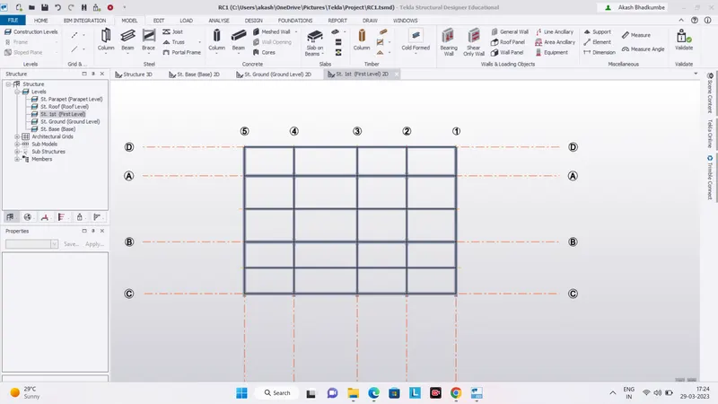
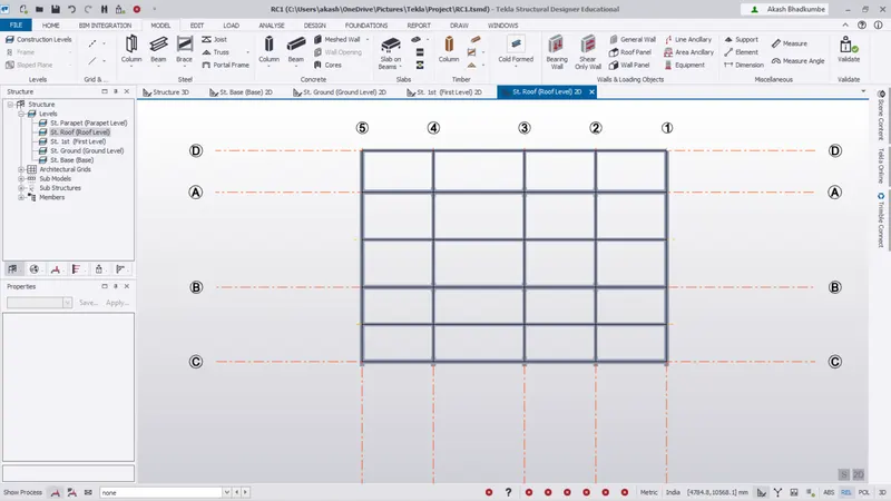
- The beams on all levels are added and validated.
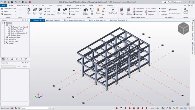
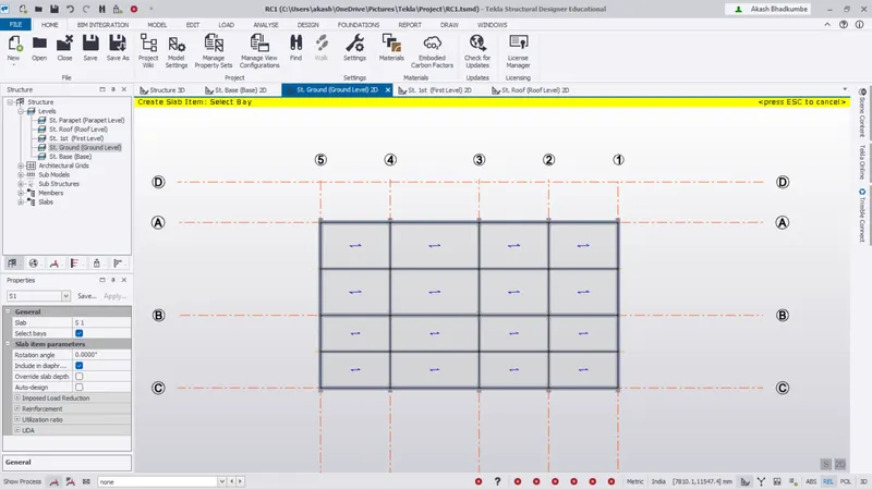
Step 3: Create slab on all levels.
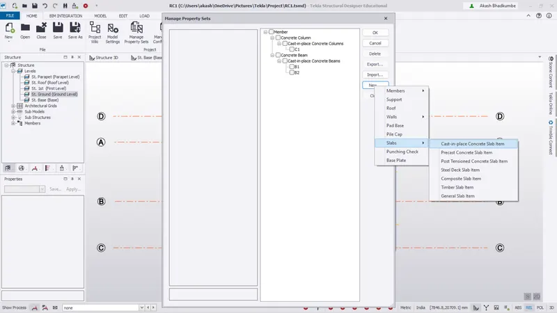
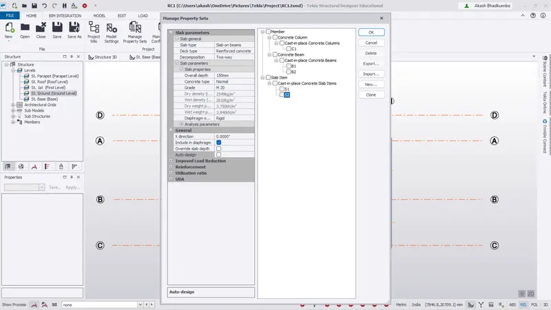
- Add property for slab from Model Property set -> New -> Slab -> Cast in Place concrete slab item.
- Create property for One way and Two ways slab.
- Go to Model -> Concrete -> Slab on Beam. Add Slab on all beams at all floor levels.
- Exculde the staircase area.
Conclusion:
- Columns, Beams & Slab are added on all floor levels.