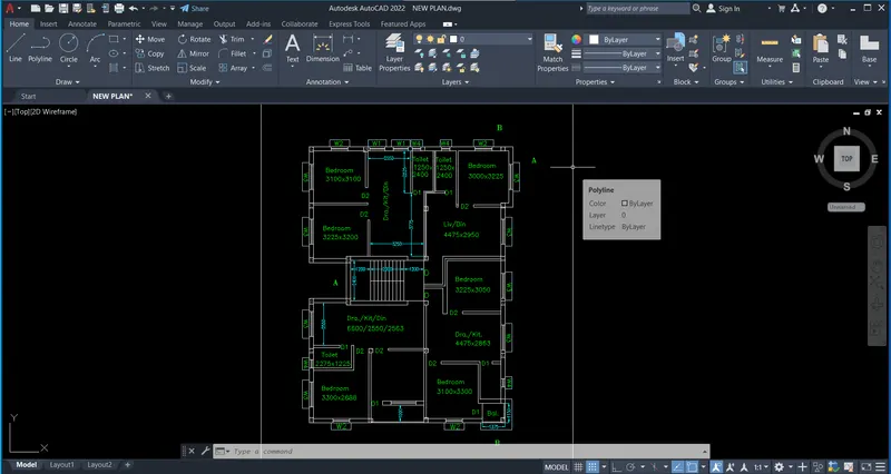
Creating a Layout, Section and Elevation with dimensions using AutoCad
AIM : To draw the given plan long with the given sections with appropriate dimensions. The drawing in the project is done with the help of AUTOCAD Software.
Procedure:
Step 1: The units of the drawing sheet is set to Engineering precision.
Step 2: Draw a construction line in horizontal and verticle direction and use the command "XL-h" & "XL-v".
Step 3: Use the "TRIM" Command and create a corner for layout by triming the extra portion of left and bottom of the corner.
Step 4: In order to create a outer wall of 250mm thick, the offset command is used with a distance of 250mm. The offset is created in both horizontal and vertical direction.
Step 5: Another offset of 125mm is created for internal walls.
Step 6: Then an offset of required room size (For example 3100 or 3300) is created from the innermost line in the vertical direction. An offset of 125mm is created for the inner wall. The extra lines are trimmed off using the "TRIM" command.