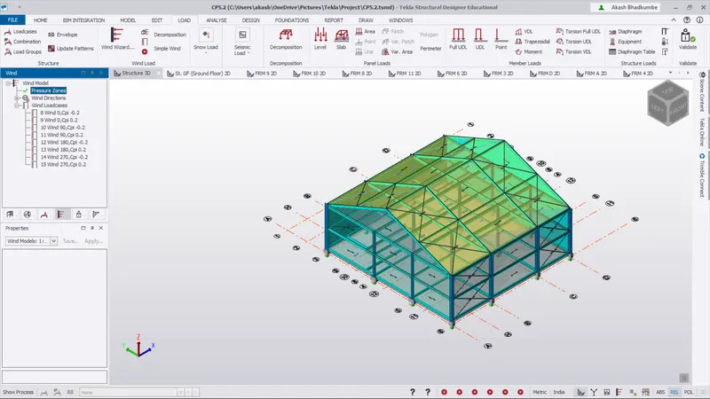
To calculate wind load for industrial steel structures and to apply it by using TSD
Q.1 Ans
Aim: Generate manual wind loading in the design report based IS code as per following input.
Procedure:
Step 1: Given data,
- Basic Wind Speed = `39 m//s`
- Terrain category = `2`
- Calculate mannually the load combination on the structure.
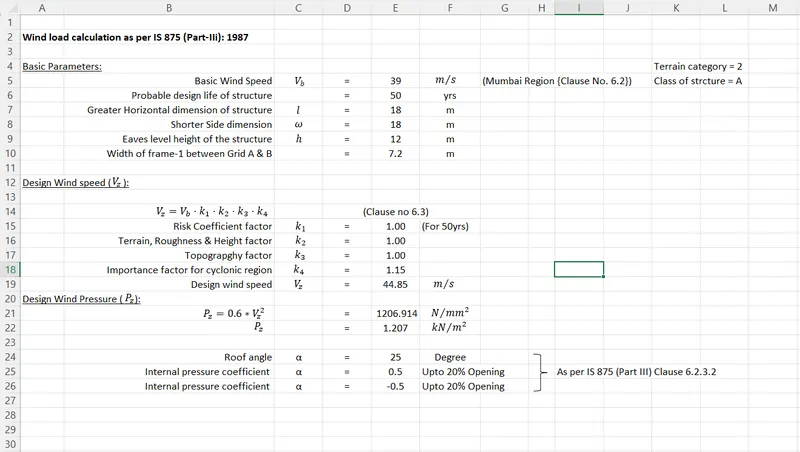
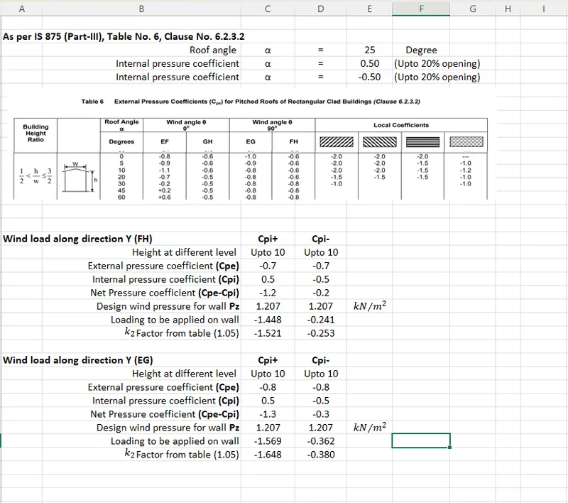
- Wall loading calculation:
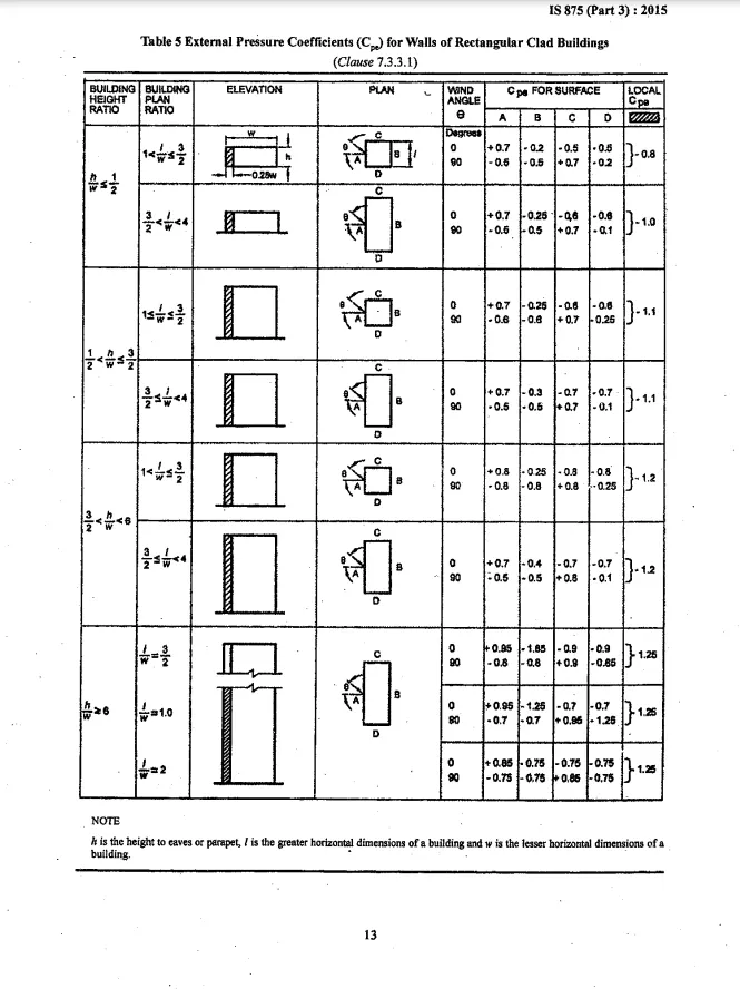
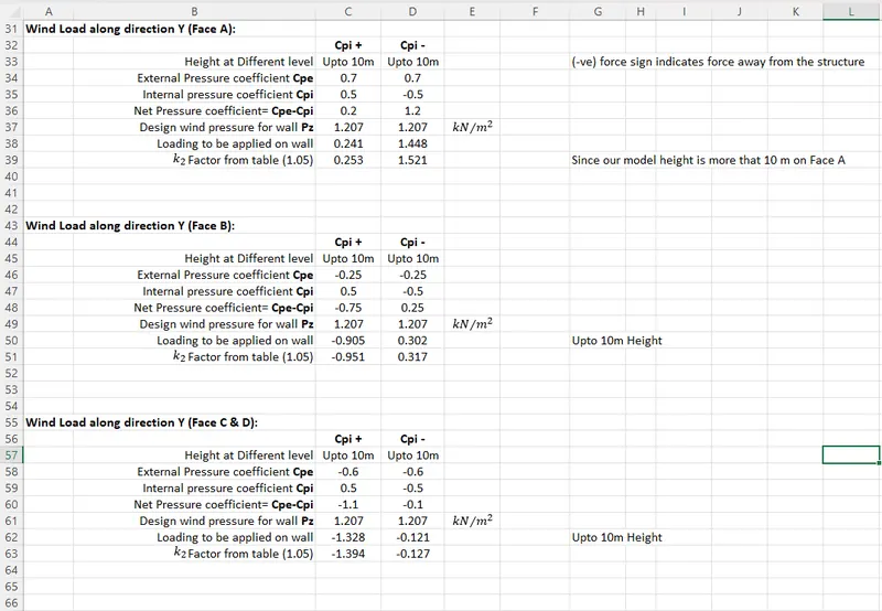
Conclusion: Mannual wind pressure is calculated for wall panels.
Q.2 Ans
Aim: Based on above calculation apply the loadings on the model.
Procedure:
Step 1:
- We have calculated the wind pressure. To apply wind pressure on model under the Tekla Structural Designer.
- We have to add the load cases. Go to Load -> Structure -> Loadcase.
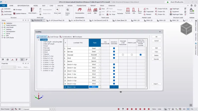
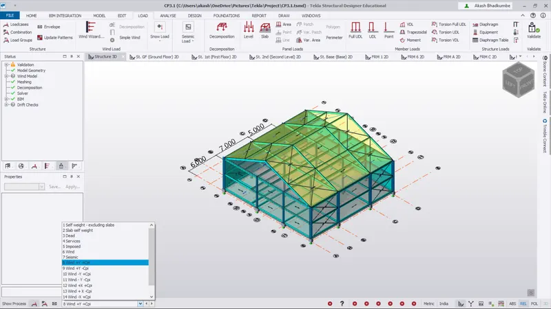
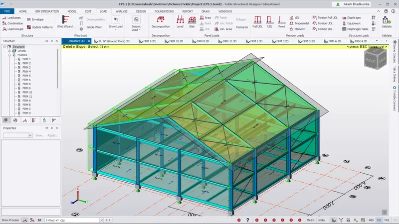
- Select the load case as Wind +Y +Cpi.
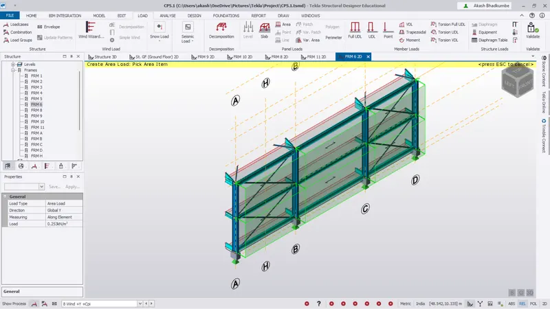
- As per the calculated value for Wind +Y +Cpi is `0.253 kN//m^2`.
- Go to Load -> Panel load -> Area load. Change the value and the direction of pressure as global Y.
- As per the calculated value for Wind +Y +Cpi is `-0.951 kN//m^2`.
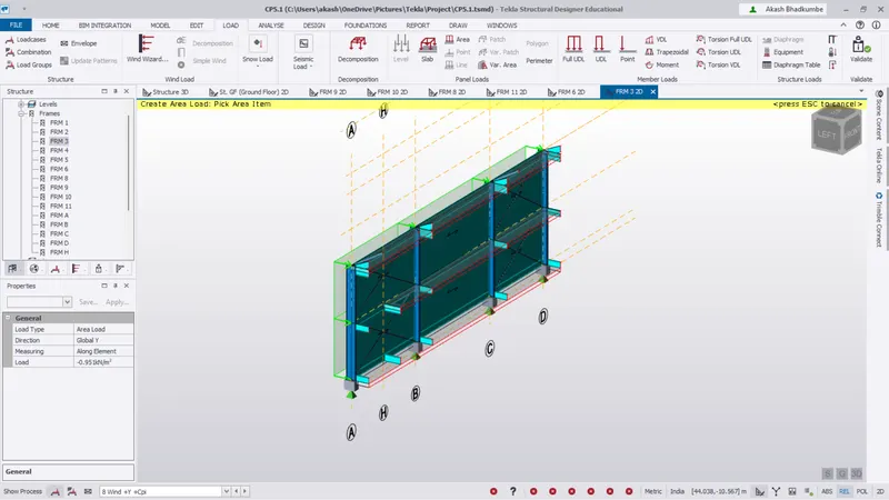
- -ve Value indicate that the pressure is acting away from the panel.
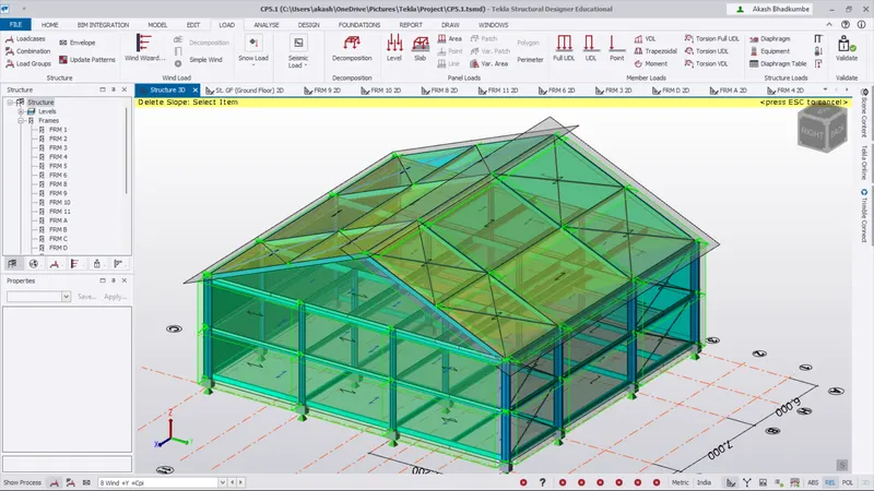
- Select the load case as Wind +Y -Cpi.
- As per the calculated value for Wind +Y -Cpi on Face B is `1.521 kN//m^2`.
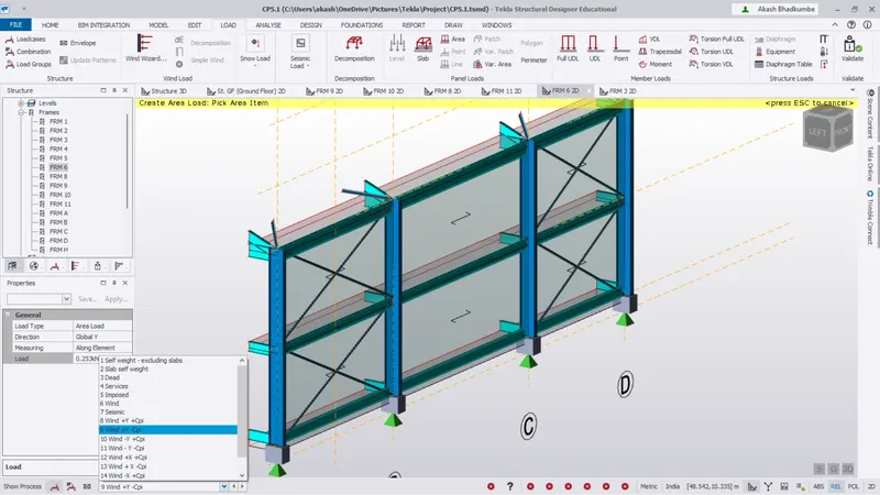
- Go to Load -> Panel load -> Area load. Change the value and the direction of pressure as global Y.
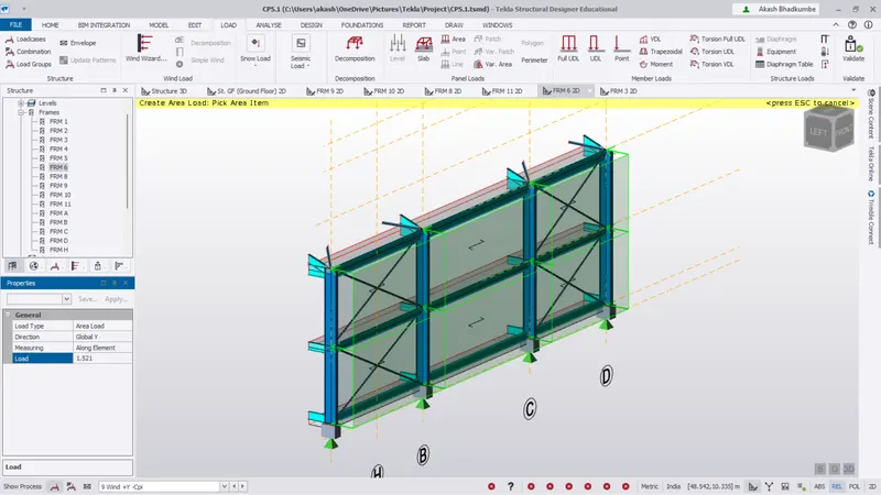
- As per the calculated value for Wind +Y -Cpi on Face B is `0.317 kN//m^2`.
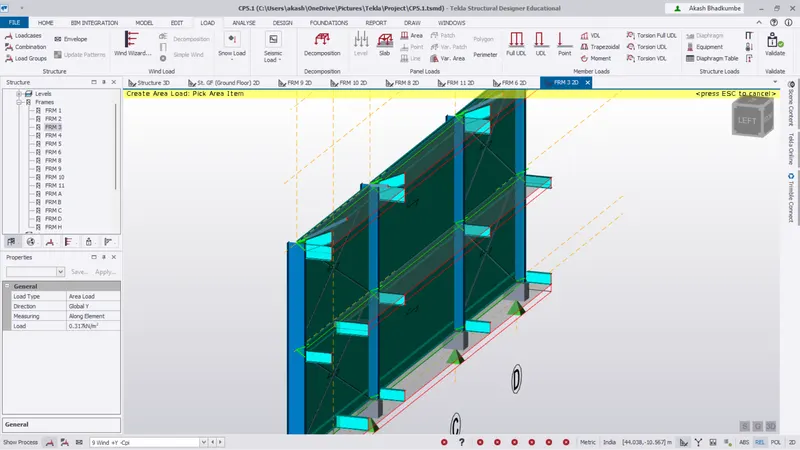
- Select the load case as Wind +Y +Cpi. Add the load cases on Face C & D.
- Go to Load -> Panel load -> Area load. Change the value and the direction of pressure as global X.
- As per the calculated value for Wind +Y +Cpi for Face C is `-1.394 kN//m^2`.
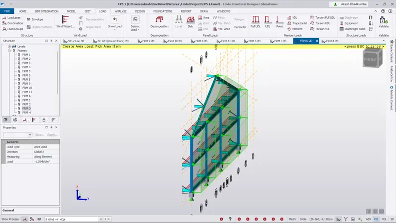
- As per the calculated value for Wind +Y -Cpi for Face C is `-0.127 kN//m^2`.
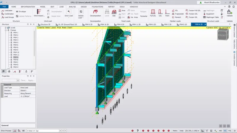
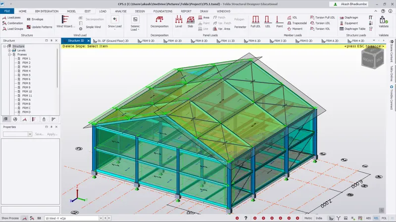
- Similraly select load case as Wind -Y +Cpi.
- As per the calculated value for Wind -Y +Cpi is `-0.253 kN//m^2`.
- All the values are same but the direction of wind intensity will be changed for respective panel.
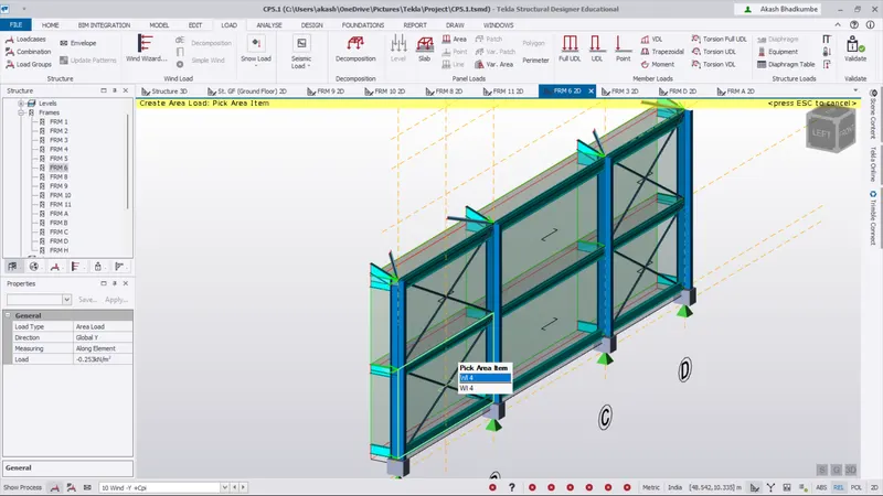
- As per the calculated value for Wind -Y +Cpi is `0.951 kN//m^2`.
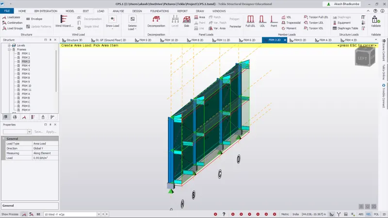
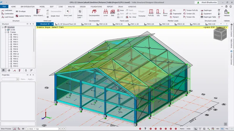
- As per the calculated value for Wind -Y -Cpi is `-1.521 kN//m^2`.
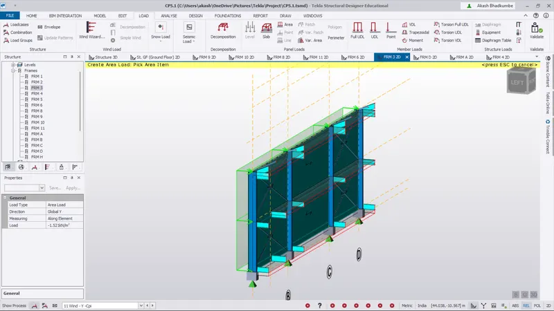
- As per the calculated value for Wind -Y -Cpi is `-0.317 kN//m^2`.
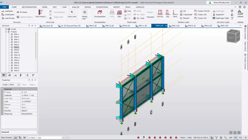
- Select the load case as Wind -Y +Cpi. Add the load cases on Face C & D.
- Go to Load -> Panel load -> Area load. Change the value and the direction of pressure as global X.
- As per the calculated value for Wind -Y +Cpi for Face C is `1.394 kN//m^2`.
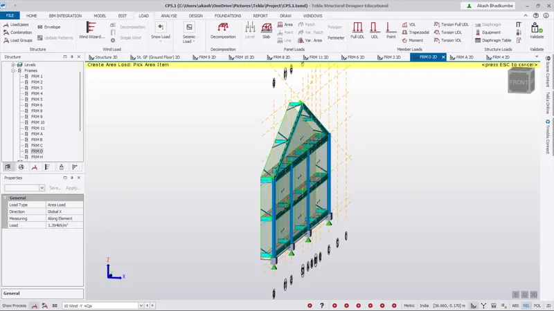
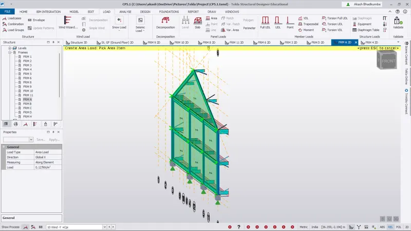
- As per the calculated value for Wind -Y -Cpi for Face C is `0.127 kN//m^2`.
Step 2:
- Similarly We will calculate the roof load and add apply on the roof.
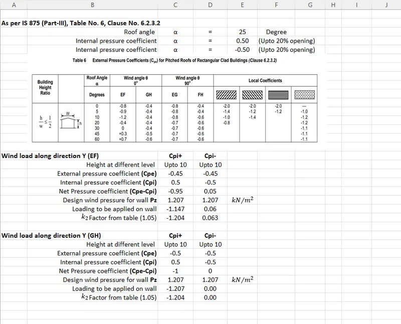
- We have Angle of roof is 25 degree.
Step 3:
- Select the load case as Wind +Y +Cpi. Consider the roof of EF.
- As per the calculated value for Wind +Y +Cpi is `-1.204 kN//m^2`.
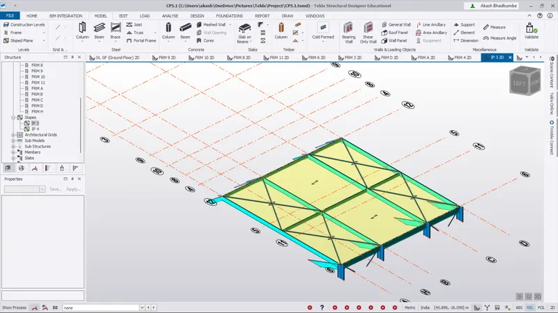
- Open the Slope frame to apply wind load on respective surface.
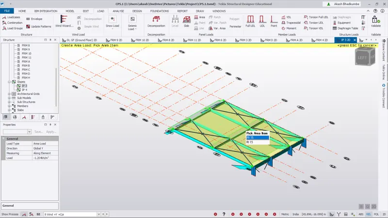
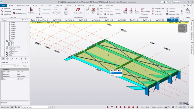
- Select the load case as Wind +Y -Cpi. Consider the roof of EF.
- As per the calculated value for Wind +Y -Cpi is `0.063 kN//m^2`.
- Select the load case as Wind +Y +Cpi. Consider the roof of GH.
- As per the calculated value for Wind +Y +Cpi is `-1.267 kN//m^2`.
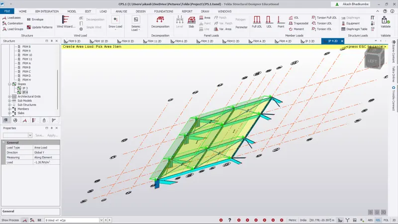
- Select the load case as Wind +Y -Cpi. Consider the roof of GH.
- As per the calculated value for Wind +Y -Cpi is `0 kN//m^2`.
Step 4:
- Select the load case as Wind -Y +Cpi. Consider the roof of EF.
- As per the calculated value for Wind -Y +Cpi is `1.204 kN//m^2`.
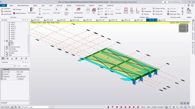
- Select the load case as Wind -Y -Cpi. Consider the roof of EF.
- As per the calculated value for Wind -Y -Cpi is `-0.063 kN//m^2`.
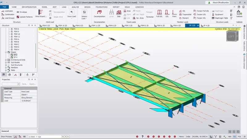
- Select the load case as Wind -Y +Cpi. Consider the roof of GH.
- As per the calculated value for Wind -Y +Cpi is `1.267 kN//m^2`.
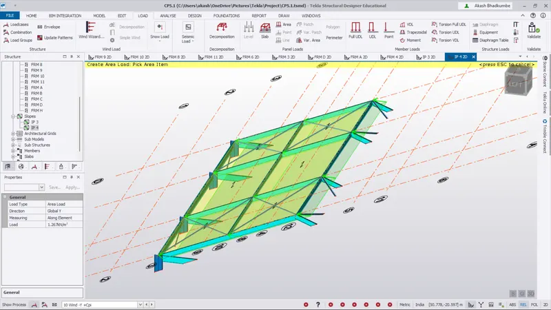
- Select the load case as Wind -Y -Cpi. Consider the roof of GH.
- As per the calculated value for Wind -Y -Cpi is `0 kN//m^2`.
Conclusion:
- Wind pressure is added on all the wall & roof panel.
- As per the calculation and according to IS 875 Part III the wind intensity for +Y +Cpi, +Y -Cpi, -Y +Cpi, -Y -Cpi is applied.
Q.3 Ans
Aim: On seperate model generate wind loading using wind wizard.
Procedure:
Step 1:
- Cope the previous model and delete all the wind load expternat & internal pressure coefficient created manually.
- Go to Load -> Structure -> Load cases and delete the Exteral & Internal pressure coefficient.
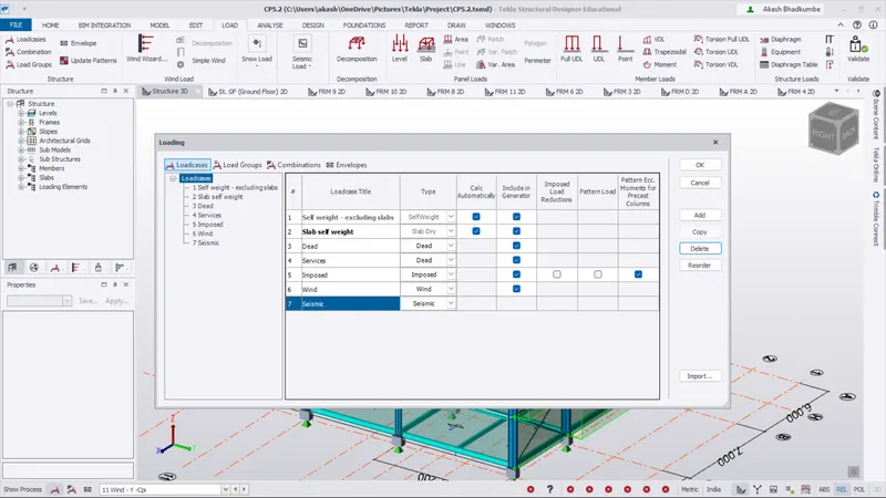
- Go to Load -> Wind Load -> Wind Wizard. Click on Consider cyclonic effect.
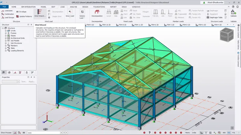
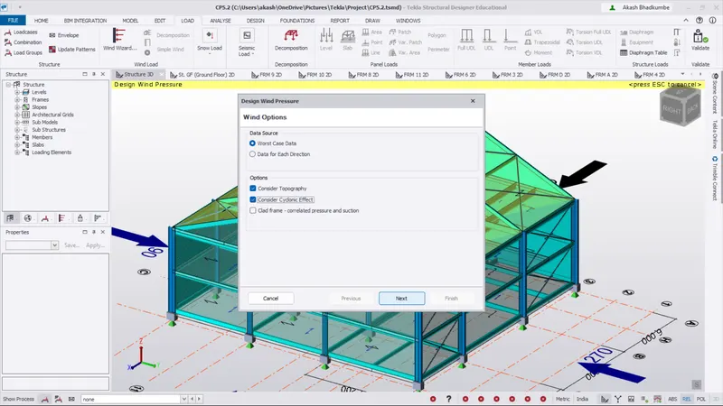
- Fill the basic data as shown below. Click on next.
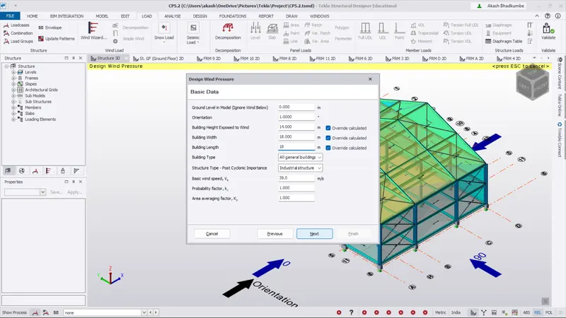
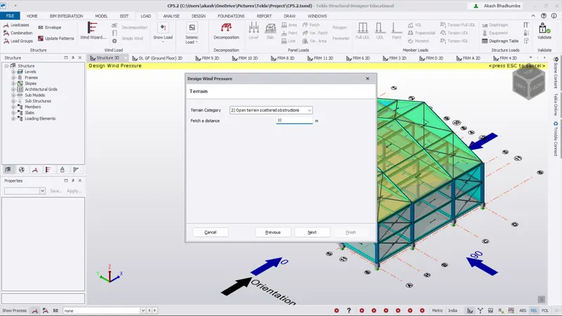
- change the Terrain category as open terrain scattered obstruction & Fetch Distance as 10m.
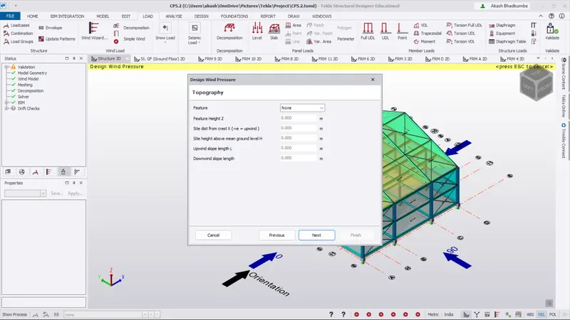
- Then click on next no need to add any data under topography.
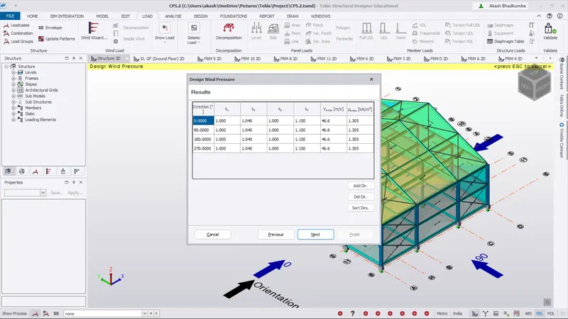
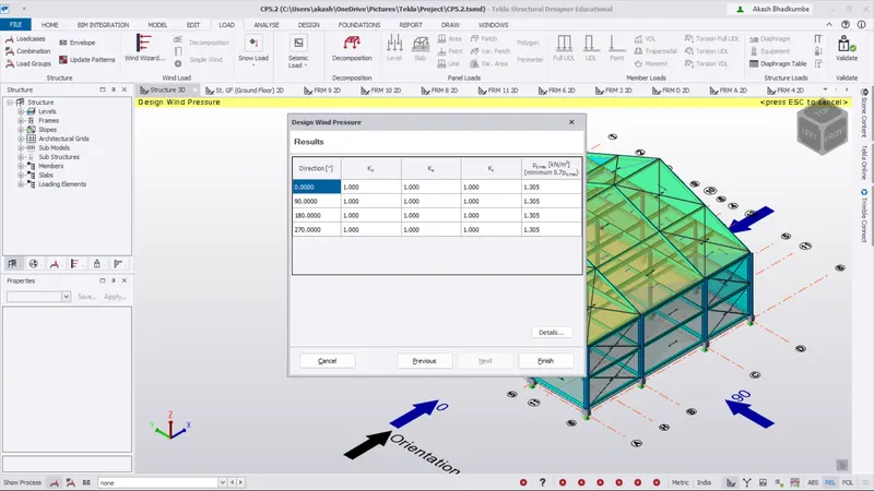
- Click on next on result.
- Go to Load -> Wind Load -> Wind loadcases.
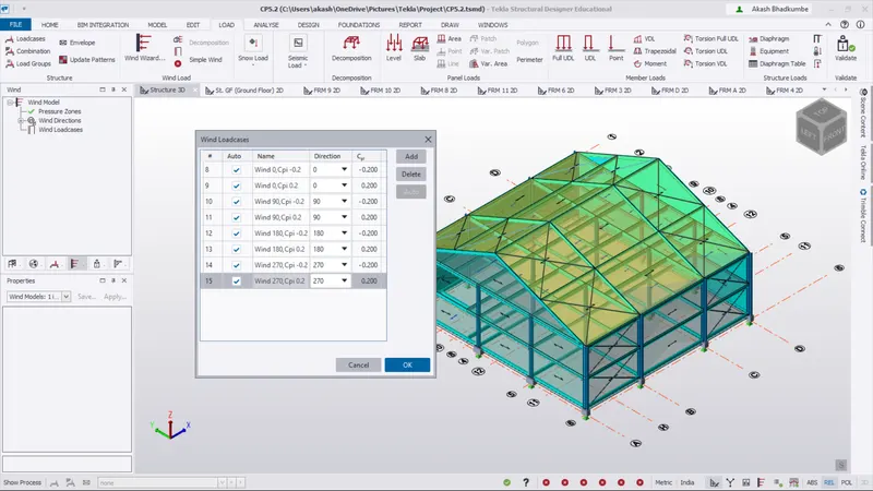
Conclusion:
- The Wind load cases are generated and Pressure coefficients are created.