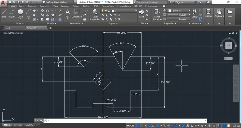
Drafting of various geometries using Chamfer, Fillet tool in AutoCad
ANS: 1
DECIMAL
Step 1: Start the drawing with "Quick Setting" And Select the "Decimal Template"
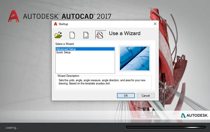
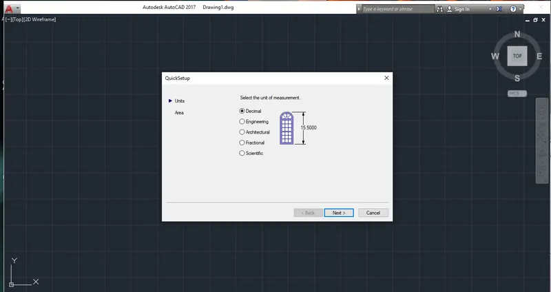
Step 2: Start the drawing with "Line" Command Start from any certain point.
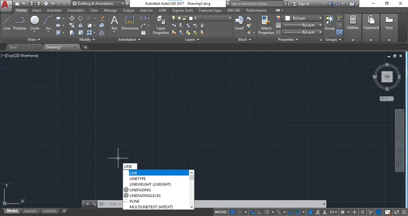
Step 3: Draw the bottom line of "3.00 Decimal"
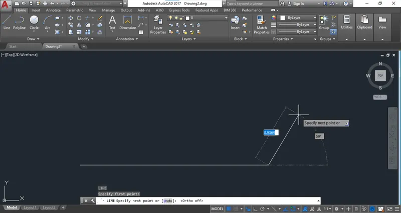
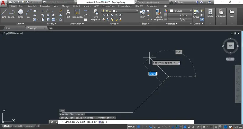
Step 4: Complete the drawing with providing all th dimension with decimal.
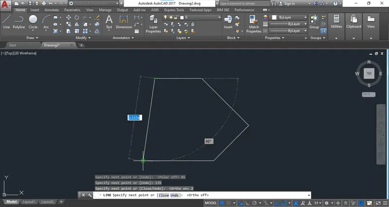
Step 5: Select the circle command.
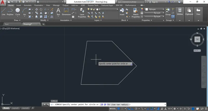
Step 6: Select the Object Snap to specify the centre of circle.
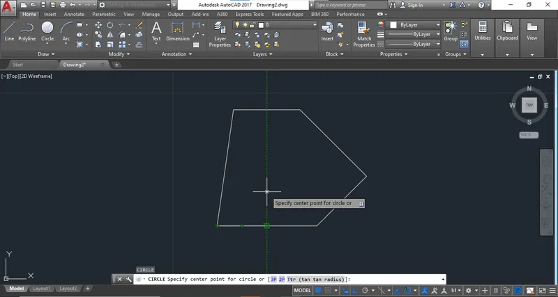
Step 7: provide the circle of snapping point complete the drawing.
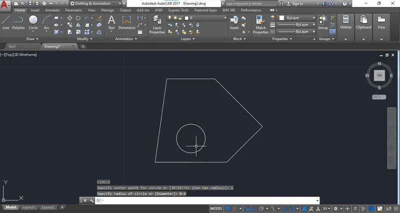
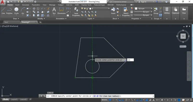
Step 8: Provide the dimensions.
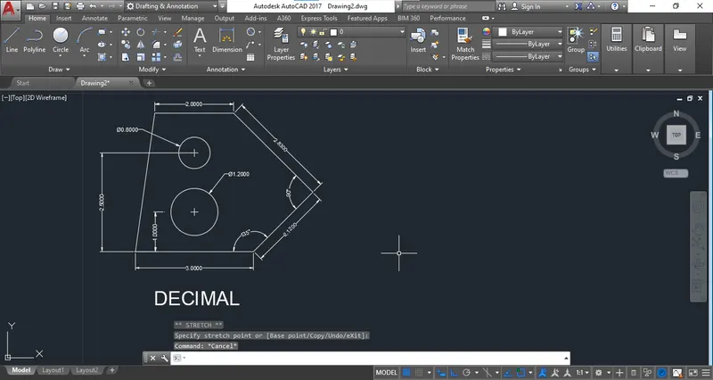
Ans 2.
ARCHITECTURAL
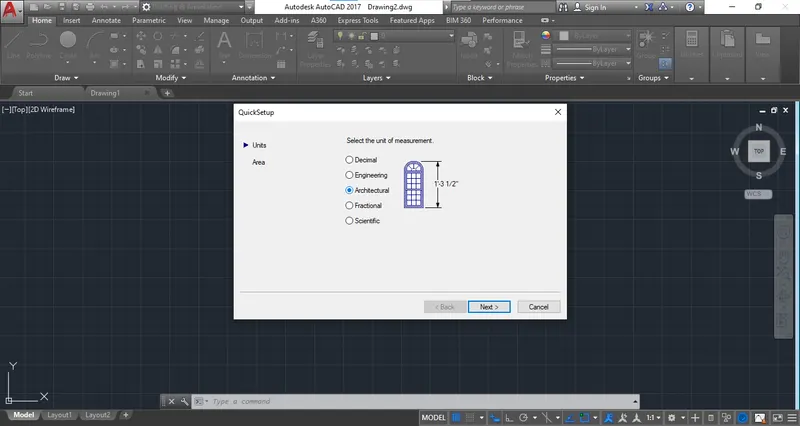
Step 1: Select the templete of "ARCHITECTURAL" From "Quick Setting".
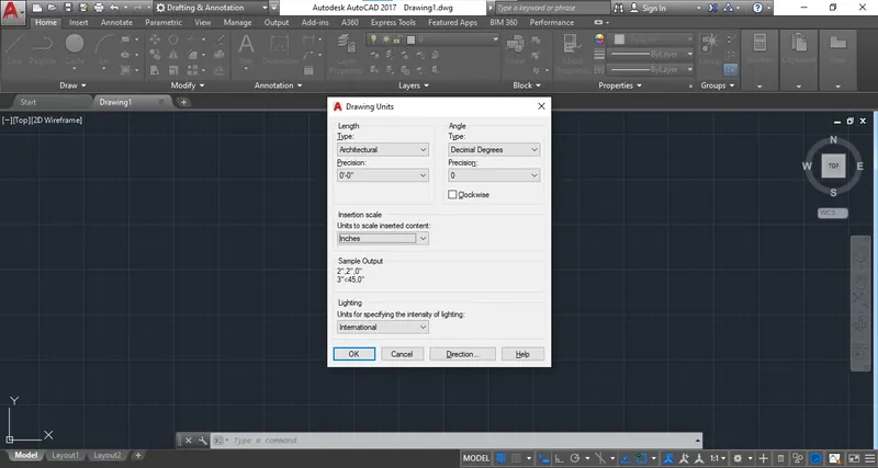
Step 2: Select the inches unit From Drawing Units.
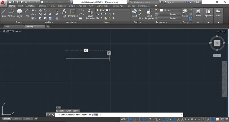
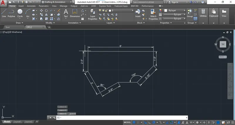
Step 3: Select the line command and the start the drawing with top line of 8'
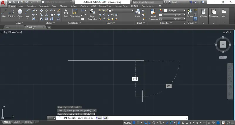
Step 4: Draw the line of 1'9"
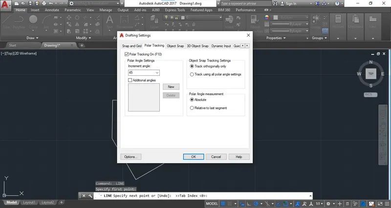
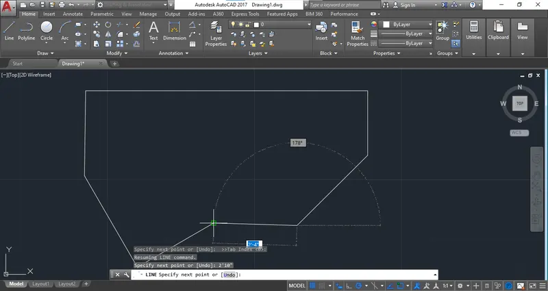
Step 5: To create the inclined angle Use polar tracking method with polar angle of 45 degree.
Step 6: Complete the drawing.
Step 7: Provide the dimensions.
ANS : 3
ENGINEERING
Step 1: Select the "Engineering Template" from "Quick setting".
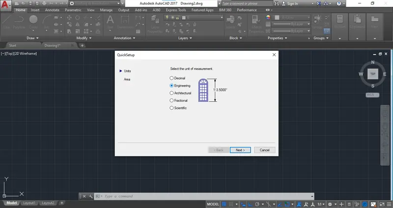
Step 2: Change setting of unit from the "Drawing Unit".
Step 3: Start the Drawing from line command and provide given dimension.
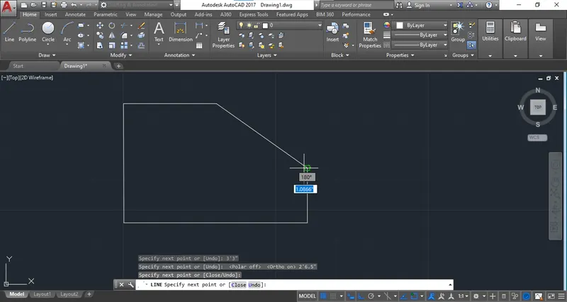
Step 4: Use Object Snap to specify centre of a circle at given distance.
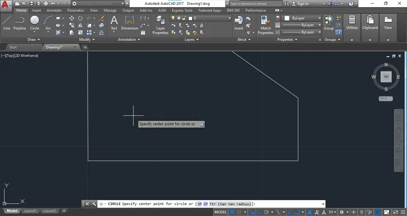
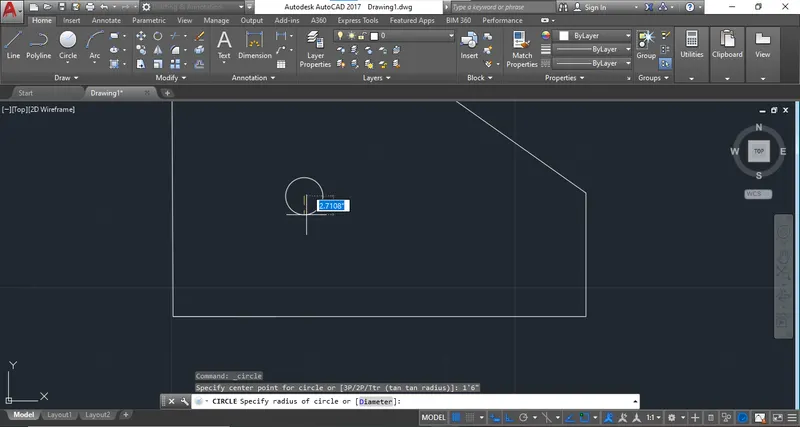
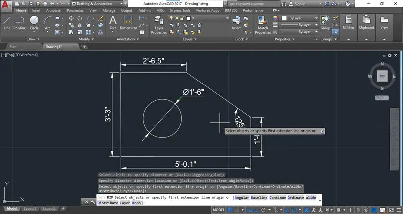
Step 5: Draw the circle with 1'6" Diameter.
Step 6: Provide the dimensions.
ANS 4
Step 1: Use the "Decimal template" From "Quick Setting"
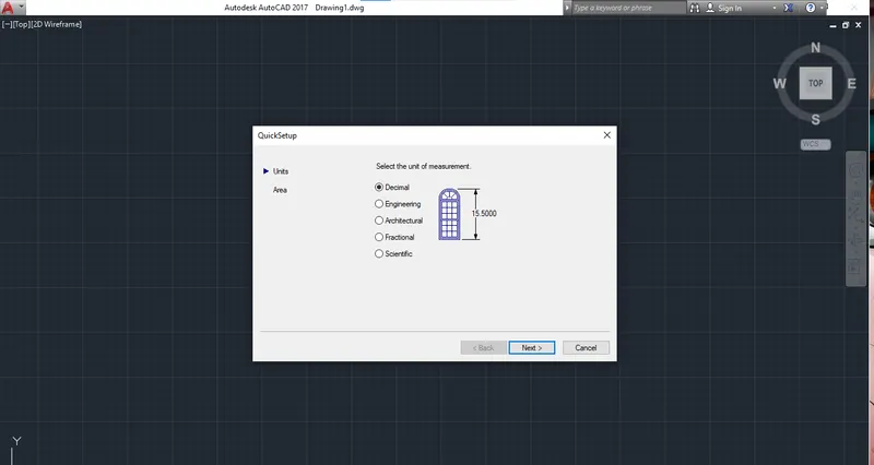
Step 2: Use the line command specify any point to start the drawing.
Step 3: Provide all the given dimension and draw the model.
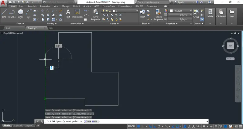
Step 4: Connect all the point by object snap which dimension is not provided.
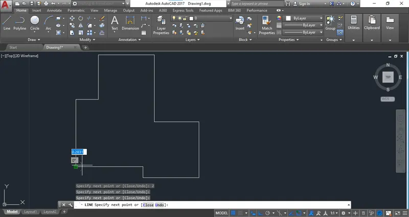
Step 5: Provide all the dimension.
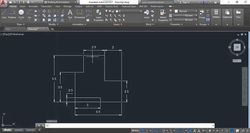
ANS 5
Step 1: Select the decimal template from Quick setting. Use the decimal unit from drawing units.
Step 2: Entre the Line command specify the point to start drawing.
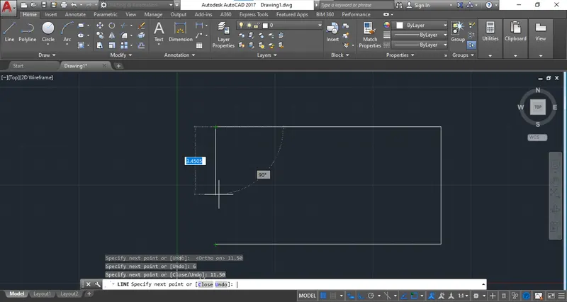
Step 3: After drawing of Rectangle specify select the circle command.
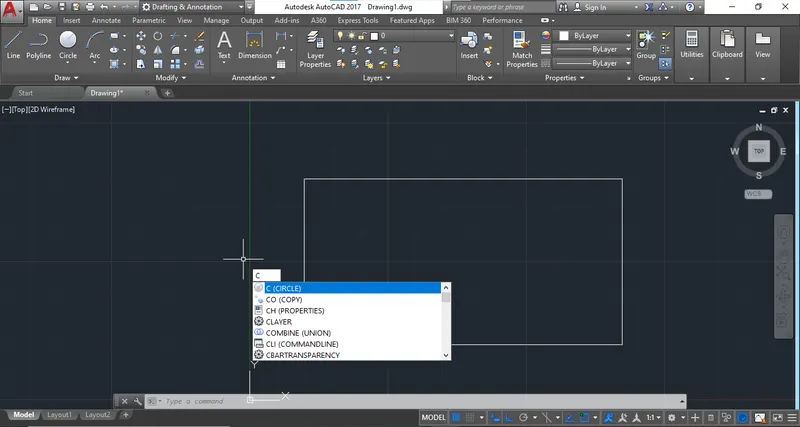
Step 4: Specify the centre point of Circle.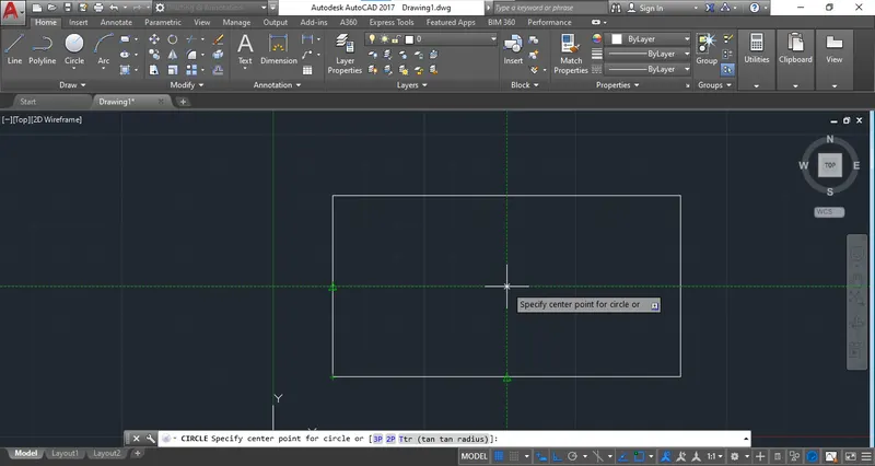
Step 5: Draw the circle of Diameter "3.00".
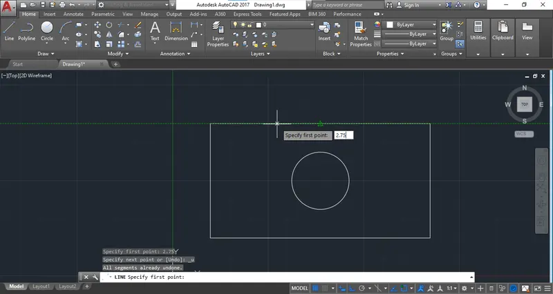
Step 6: Draw the line from centre at "2.75"
Step 7: Draw the circles at Left and right by using object snap method.
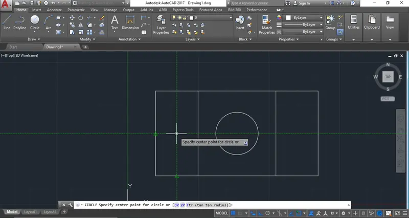
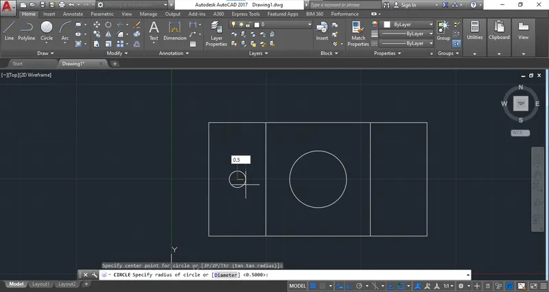
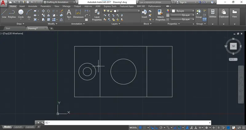
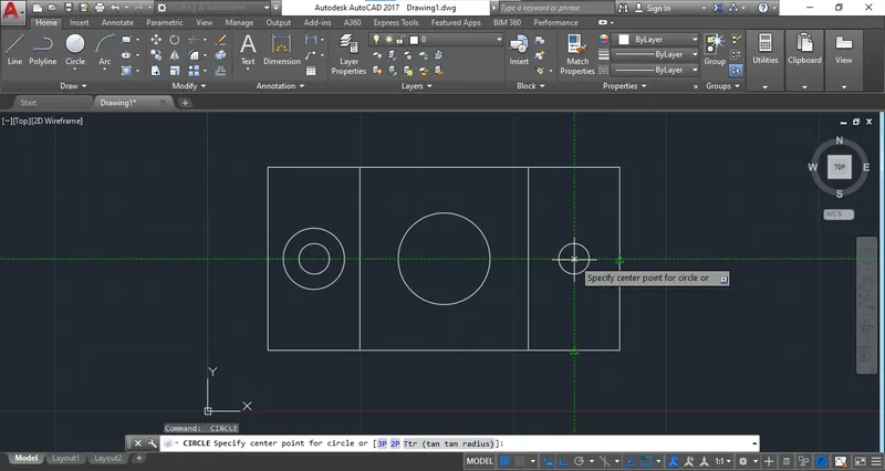
Step 8: Provide the dimension.
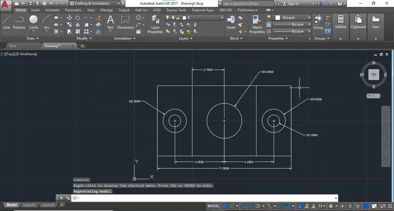
ANS 6
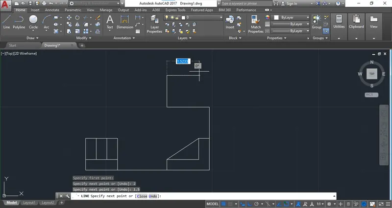
Draw the elevation plan and side view
Step 1: Use the "Decimal Template" from "Quick Setting".
Step 2: Select the "Line" Command and start the drawing by specifying any point.
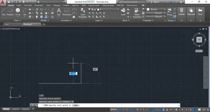
Step 3: Start the Front view To draw.
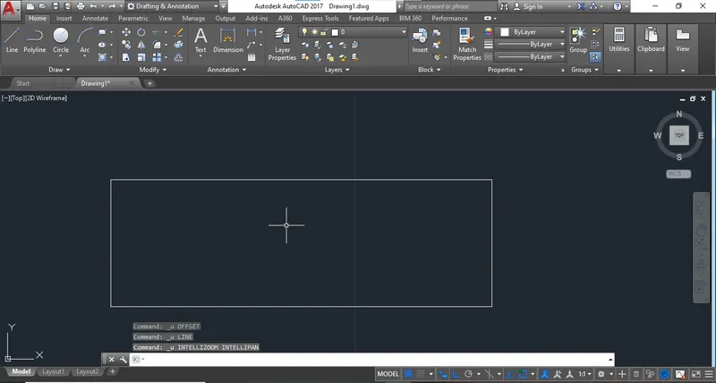
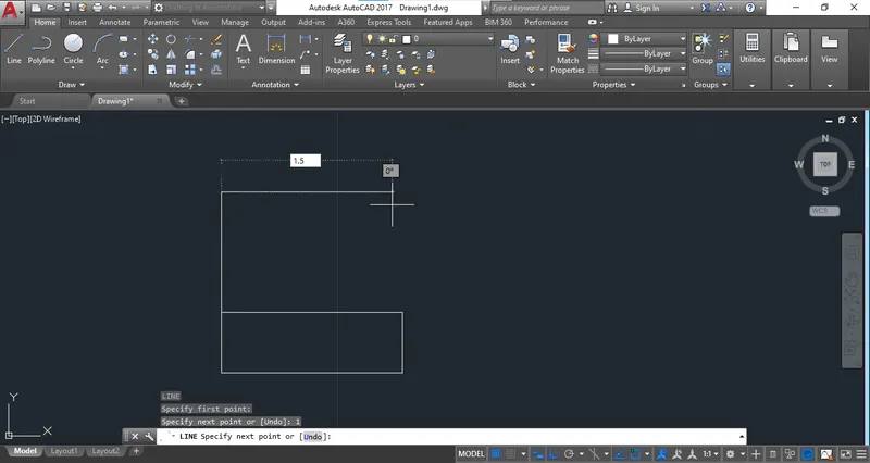
Step 4: Draw one by one
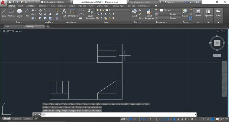
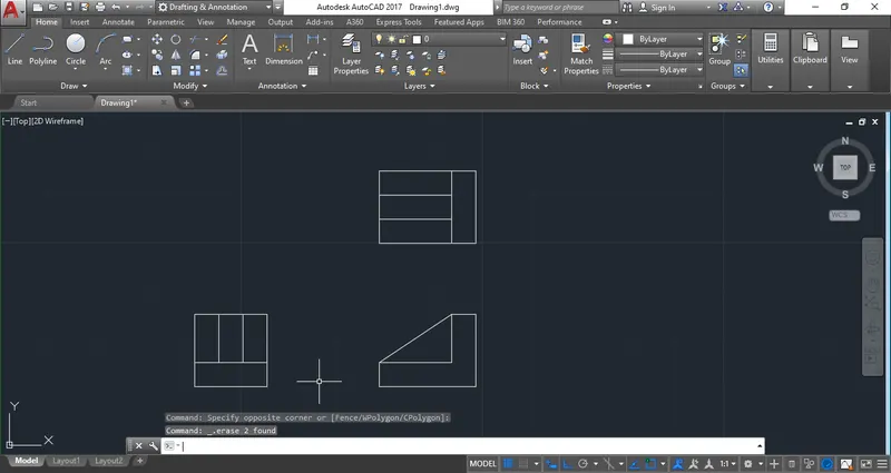
Step 5: Delete the refference line.
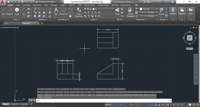
Step 5: Add dimensions
ANS 7
Step 1: Start the drawing with decimal template from quick setting.
Step 2: Start the drawing with line command and use the fillet command for joint the corners.
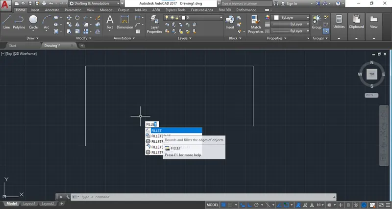
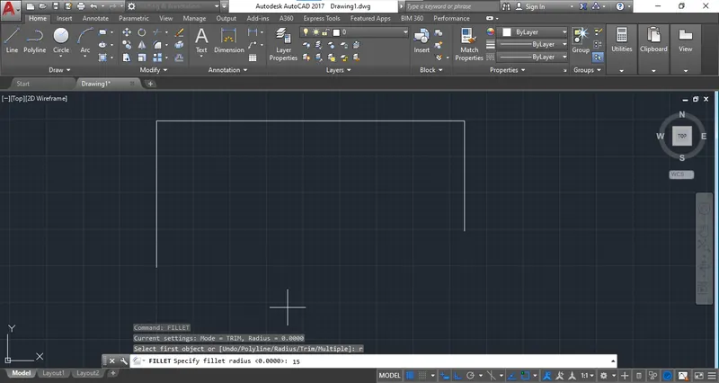
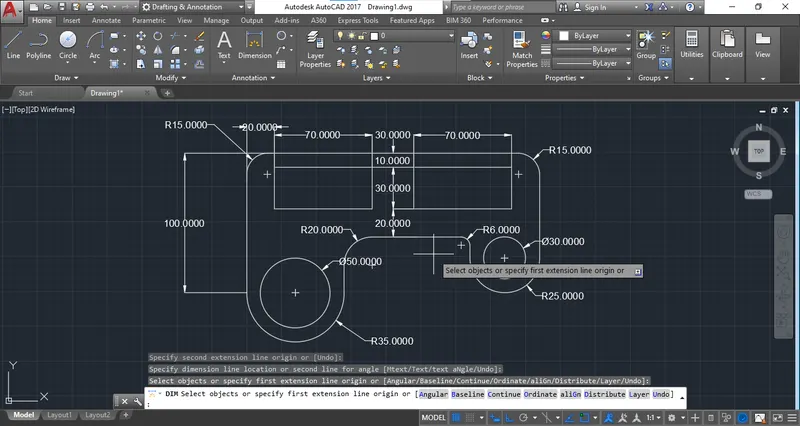
Step 3: In Fillet select the radius and give the radius as given in drawing.
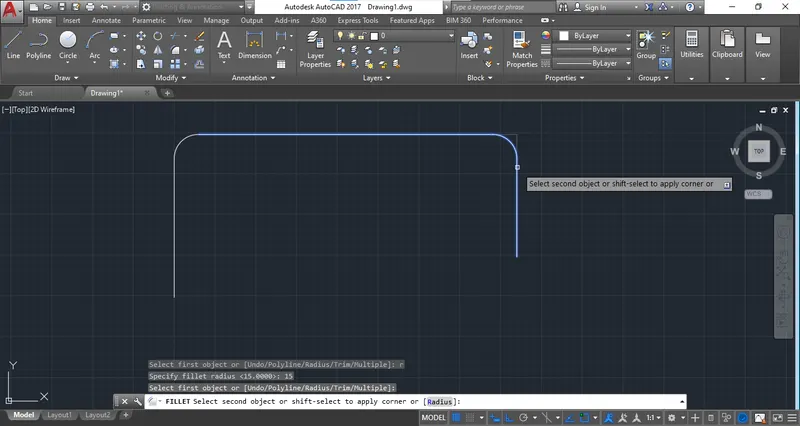
Step 4: Create Line with a offset of "70" to provide an arc of "35".
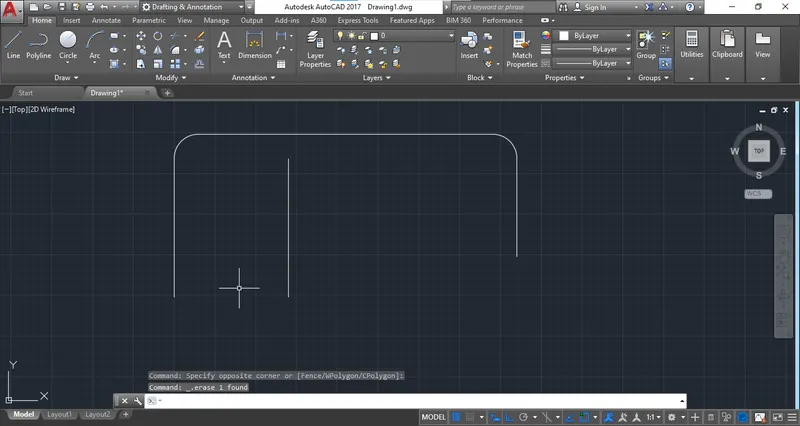
Step 5: Select "Start End Radius" Arc to create the arc.
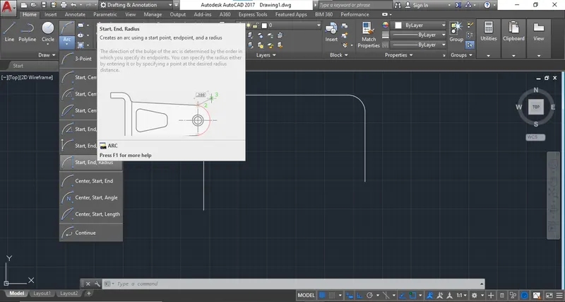
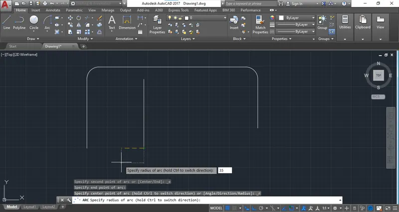
Step 6: Create a circle at with object snap method.
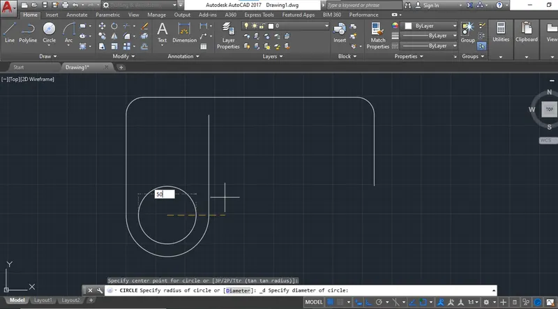
Step 7: create the same fillet procudre for creating the next part
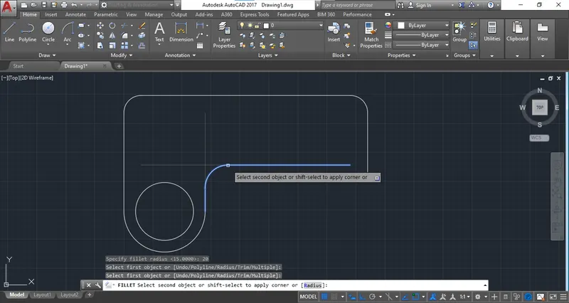
Step 8: Repeat the procedure to complete other side.
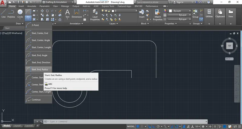
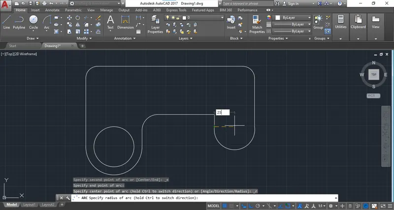
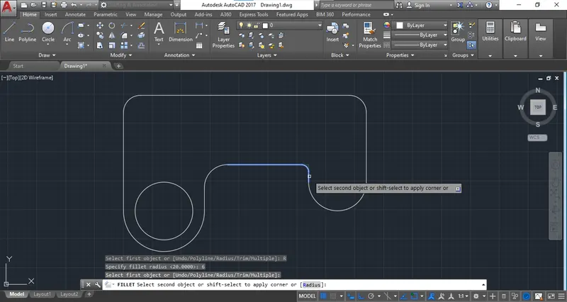
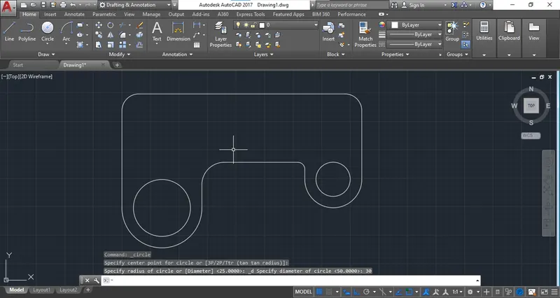
Step 9: Create a Rectangle at specified poit by using object snap.
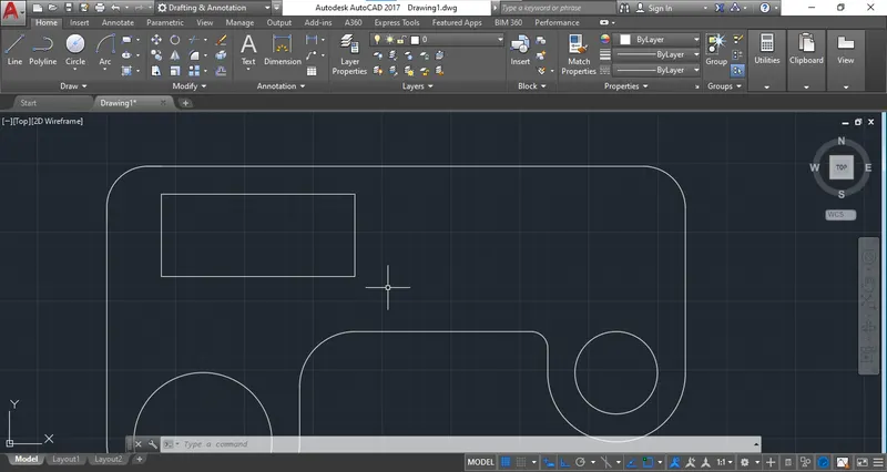
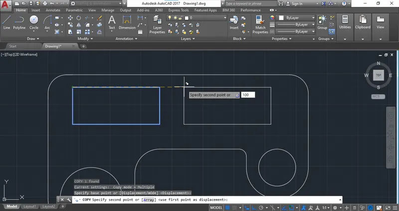
Step 10: Next is the same rectangle so use "COPY" Tool and copy at the distance of "100" from start point of rectangle.
Step 11: Provide all the dimensions.
ANS 8
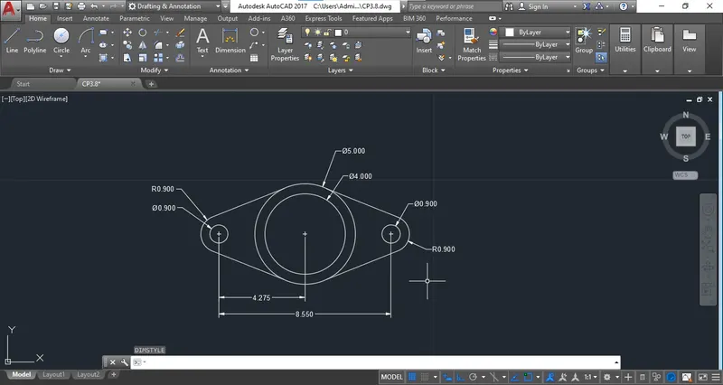
Step 1: Use "Decimal Template" From "Quick setting" Use the decimal unit from Drawing units.
Step 2: Draw a circle at any centre point.
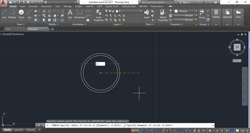
Step 3: Use object snap to take the centre of left and right side portion.
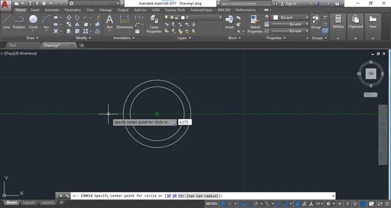
Step 4: Draw a centre line at left or right side circle to draw arc at outer side.
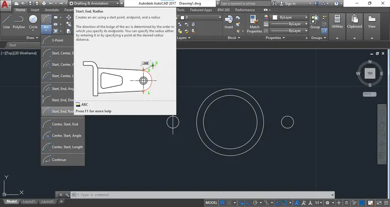
Step 5: Create a arc at outer side and repeat the procedure for right side.
Step 6: select the tangent object snap to create the line line from cirlcles tangent point to arc.
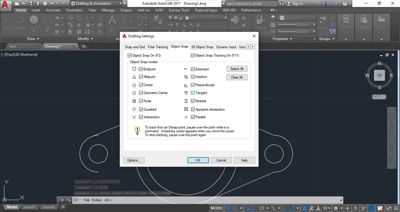
Step 7: The tanget snap will be select the tanget point and trim the extra portion.
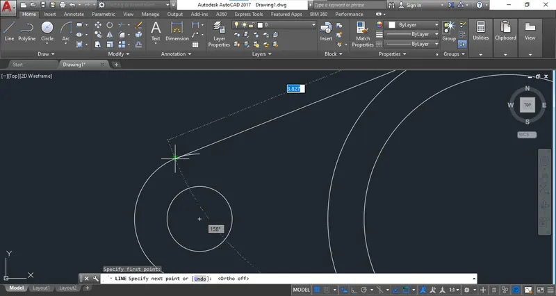
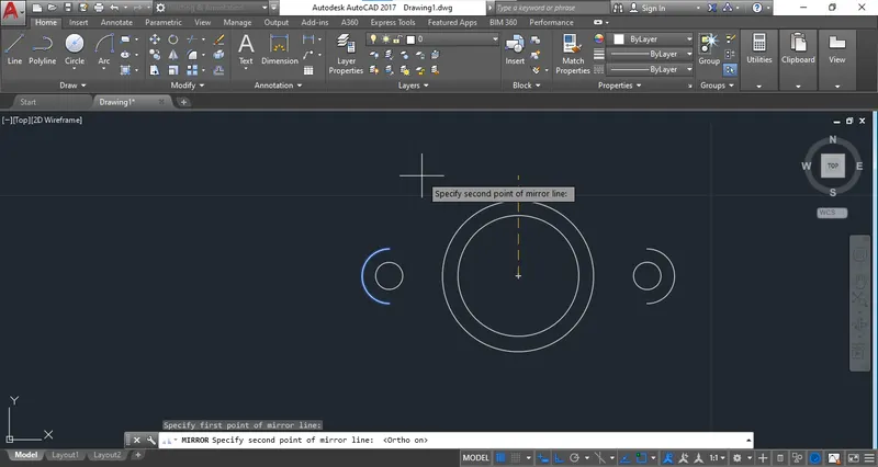
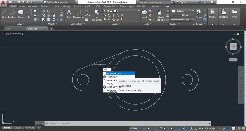
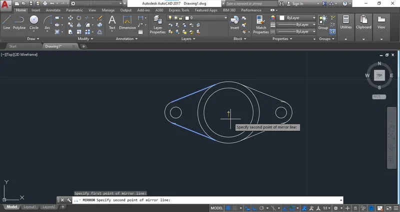
Step 8: Use Mirror tool and complete all the sides.
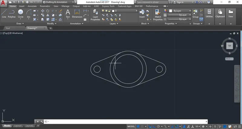
Step 9: Provide the dimensions.
ANS 9
Step 1: Start the drawing with "Engineering template" From "quick setting"
Step 2: Select the circle command and create the circle at certain point with 8' Radius.
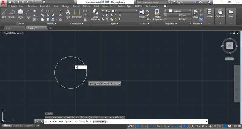
Step 3: Use the object snap to specify the centre of second circle.
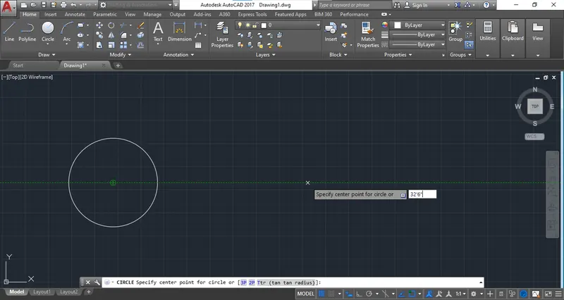
Step 4: Draw the circle at the point with radius of 9'
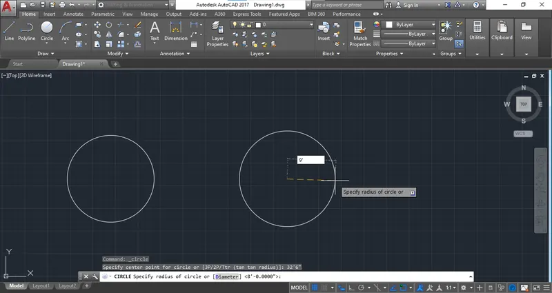
Step 5: Use the fillet Command and the radius of 20'10"
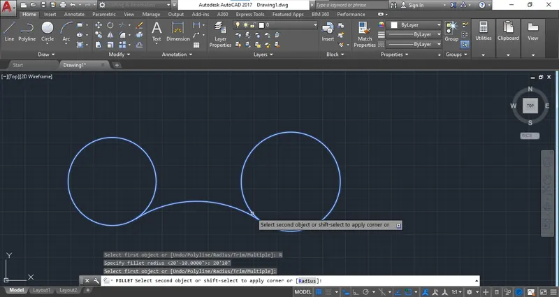
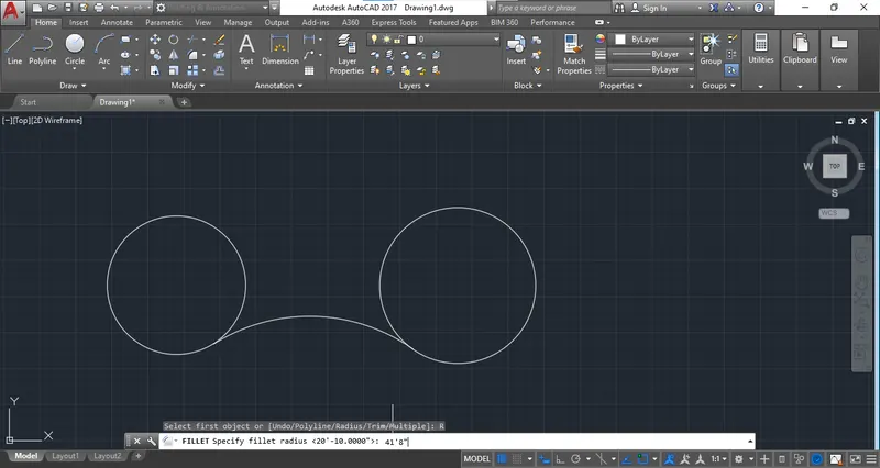
Step 6: Select the "Tan-Tan-Radius" create the outer arc of the circle.
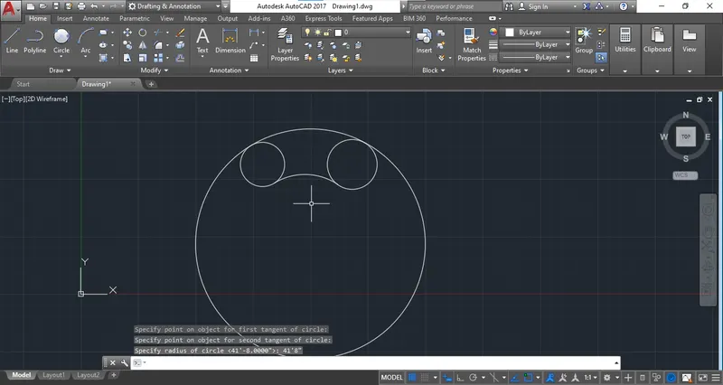
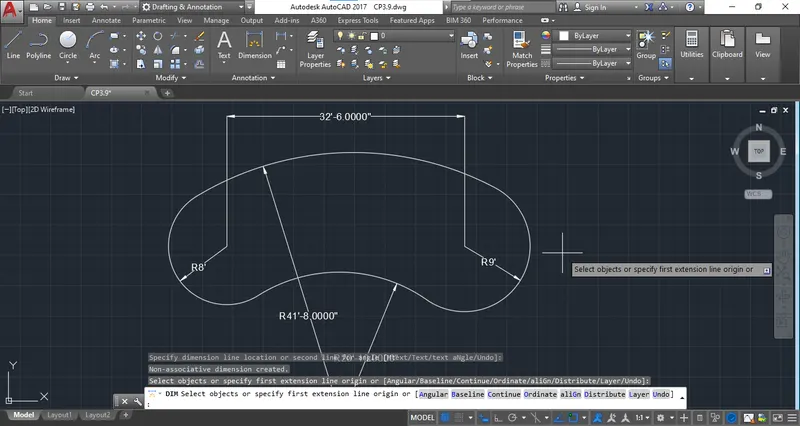
Step 7: Trim the extra part and provide the dimension.
ANS 10
Step 1: Choose any Template from quick setting. I am selecting the Engineering template and setting drawing unit as a "Inches".
Step 2: Use the polar angle of 45 degree and complete the drawing.
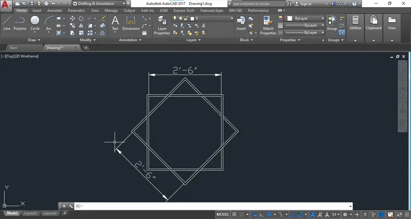
Ans 11
Step 1: Select the Engineering Template from Quick setting and
Step 2: Select the line command and start drawing at certain point.
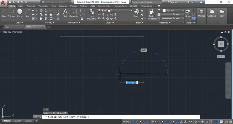
Step 3: Provide the given dimension and complete drawing.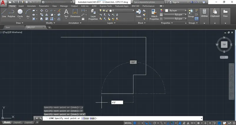
Step 3: Use object snap command where to needed and complete the model.
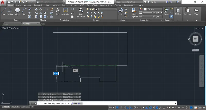
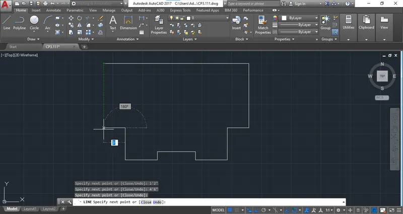
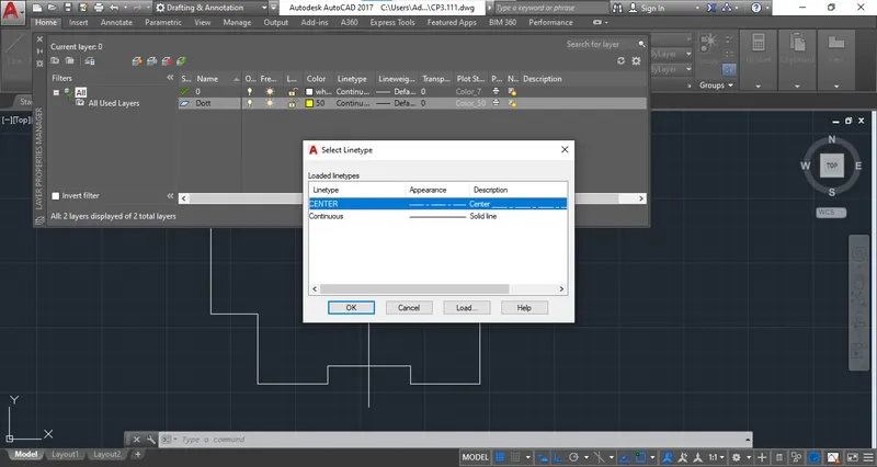
Step 4: I am Creating a new layer with different colour with dott line.
Step 5: Create a notch at the right side by using polar tracking of 30 angle.
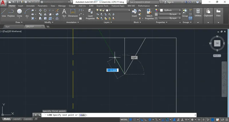
Step 6: Repeat the process for left portion.
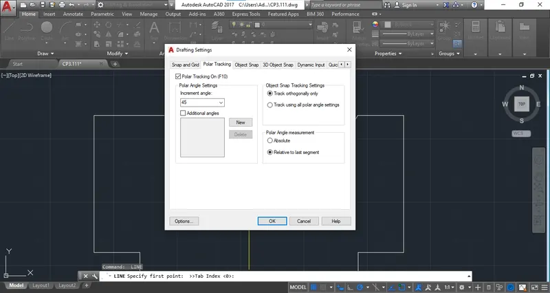
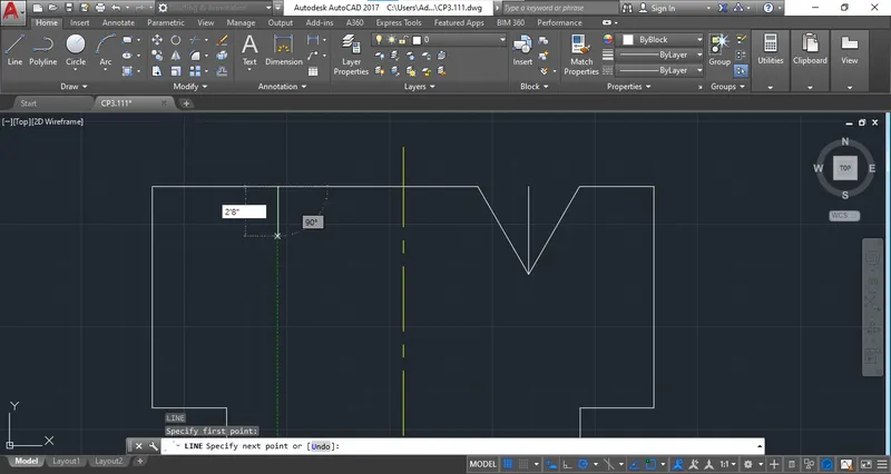
Step 7: Complete the drawing and provide dimension.