Creating 3D Isometric view of various structural elements in AutoCAD
Q.1 Ans
Aim: Create a 3D isometric view with plan and elevation as given.
Procedure:
Step 1:
- All the dimensions are in Feet and inches so select the imperical unit.
- Draw the line plan of the structure.
- Use the required commands for drawing the lineplan.
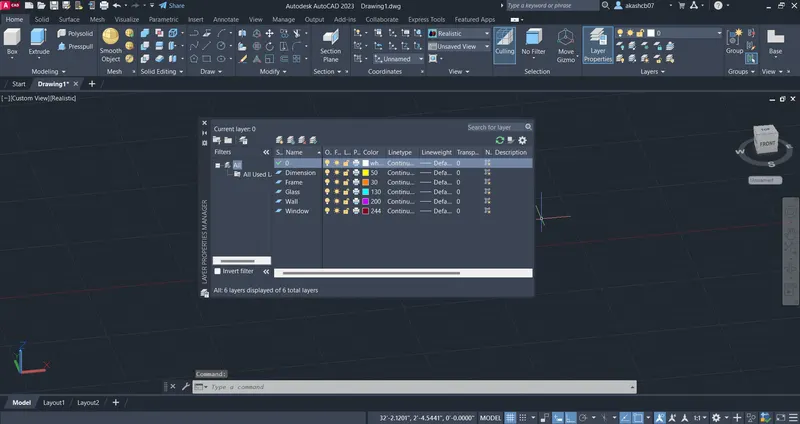
- Create the layers for wall, window, dimensions, glass etc.
- After creating the lineplan change the workspace from 2D drafting to 3D modelling.
- As entering in the 3D modelling use the view cube for change the various views.
- Then use the Extrude command or use presspull command to create a wall.
- Provide height to the wall as 10'.
- As the walls are created the window portion will be remain open.
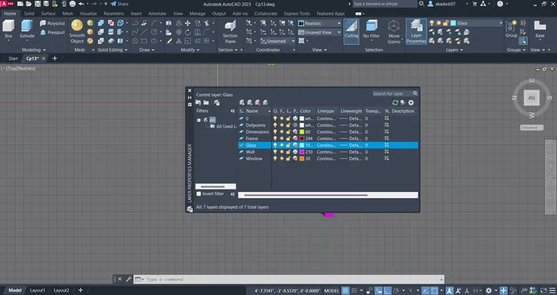
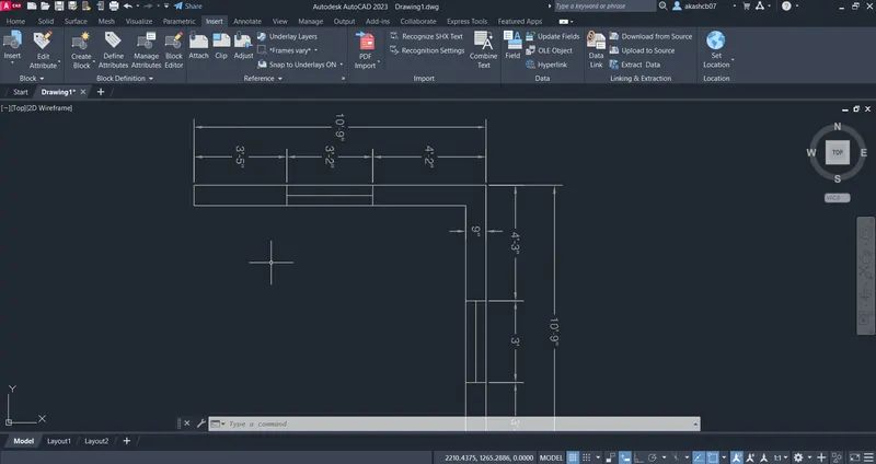
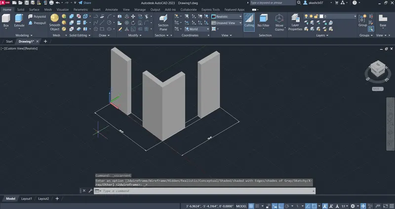
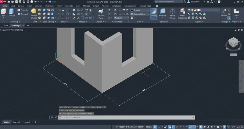
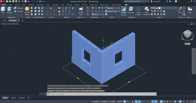
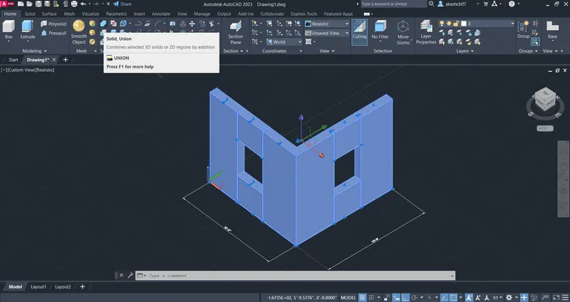
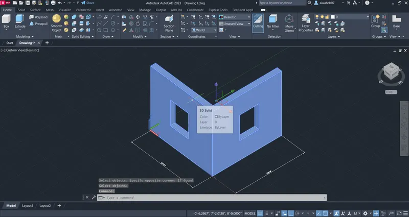
- Wall are created with window openings. All the parts are separate so create a single member to it.
- Use the union command to create a wall as a single member.
- Select all walls and use union and press entre.
Step 2:
- Walls are created with openings.
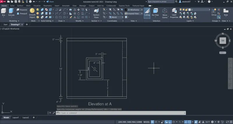
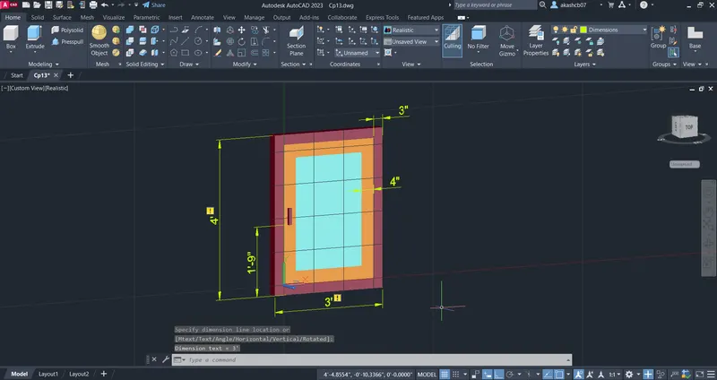
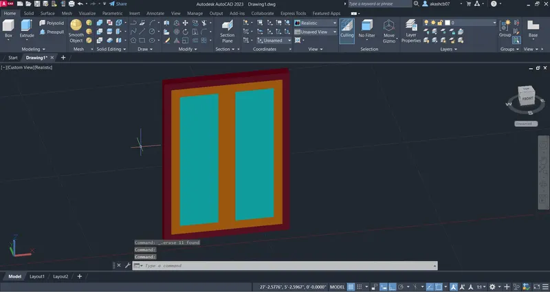
- Now create a window of size 3' x 4' from elevation A.
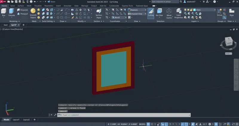
- Create a 3" thick window frame, select a color for frame and use the extrusion to give thickness.
- Create a window of 4" thickness with different colour and provide thickness for the same.
- Create a glass portion to window and handle then provide the dimwnsions.
Step 3:
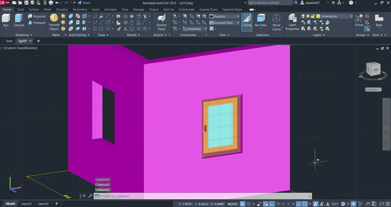
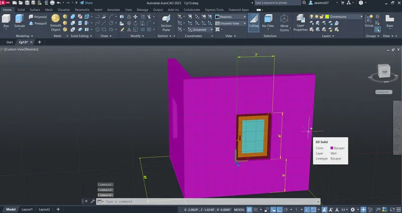
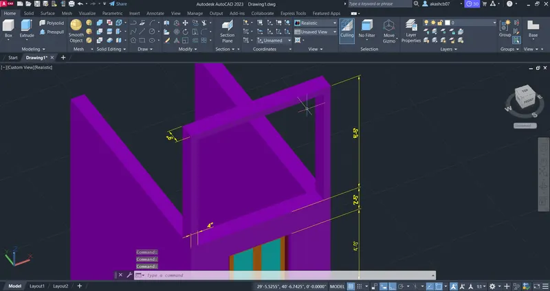
- Fix the created window to the cut section.
- The Elevation at A will be created.
Step 4:
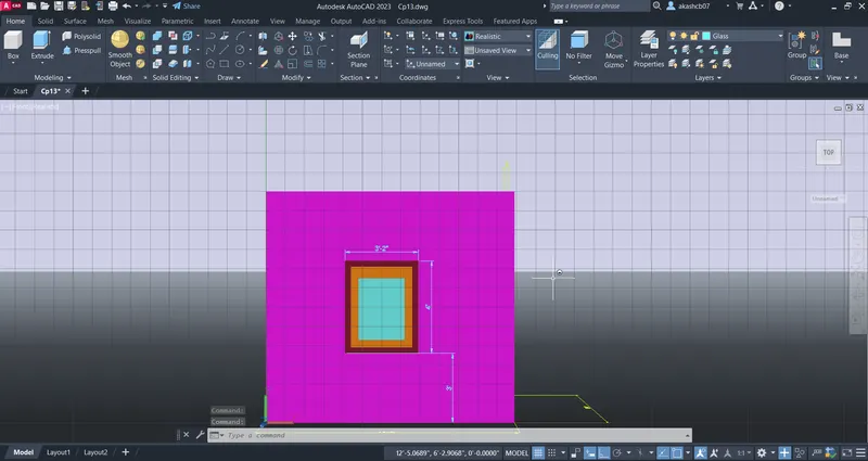
- Repeat the same procedure and create the window of 3'2" x 4'.
- Fix the window at tha cut section of wall and provide the dimension.
- The elevation at B will be created.
Result:
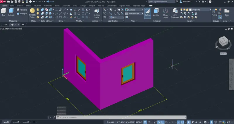
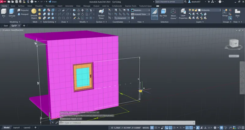
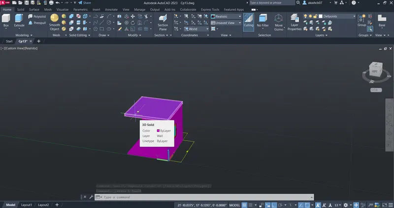
Q.2 Ans
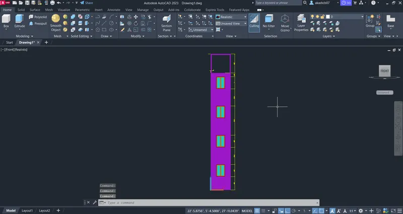
Aim: Create a 3D elevation of building facade.
Procedure:
Step 1:
- All the dimensions are in Feet and inches so select the imperical unit.
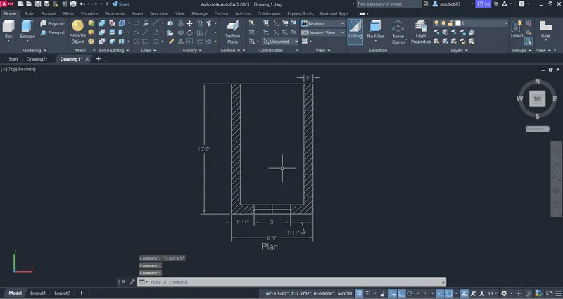
- Draw the line plan of the structure.
- Use the required commands for drawing the lineplan.
- Create the layers for wall, window, dimensions, glass etc.
- After creating the lineplan change the workspace from 2D drafting to 3D modelling.
- As entering in the 3D modelling use the view cube for change the various views.
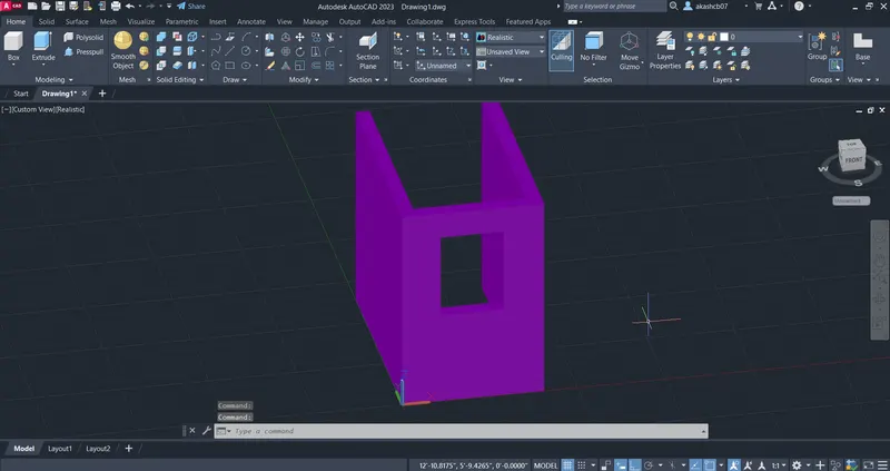
- Then use the Extrude command or use presspull command to create a wall.
- Provide height to the wall as 9'11".
- As the walls are created the window portion will be remain open.
Result:
Q.3 Ans
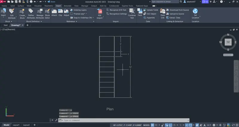
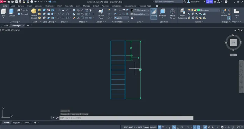
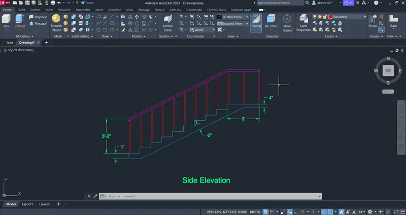
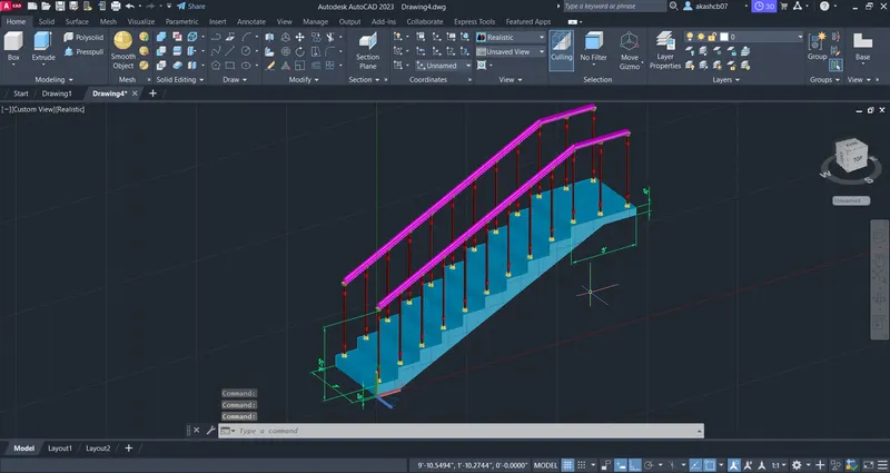
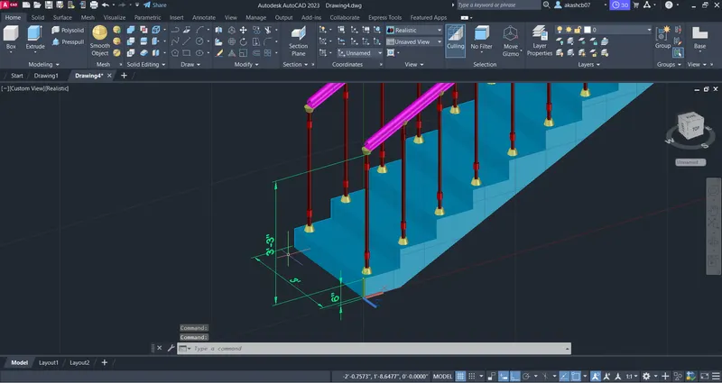
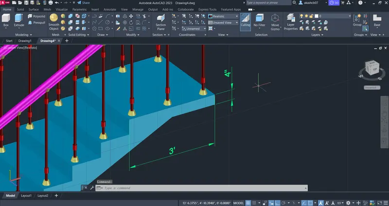
Aim: Create the ismoteric 3d view of a stair with railing as shown in the plan and elevation.
Procedure:
Step 1:
- All the dimensions are in Feet and inches so select the imperical unit.
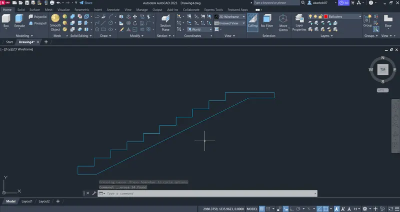
- Draw the line plan of the staircase.
- Use the required commands for drawing the lineplan.
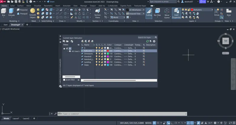
- Create the layers for Baluster, Handrails, Steps etc.
- After creating the lineplan change the workspace from 2D drafting to 3D modelling.
- As entering in the 3D modelling use the view cube for change the various views.
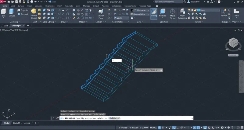
- Then use the Extrude command or use presspull command to create a Staircase width.
- Provide width for staircase as 3'.
Step 2:
- Create a Handrails for staicase with 3' height.
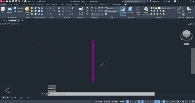
- First create the ballusters which is the vertical members of the handrails.
- I have created the ballusters with 3' hieght and provided a designed shape by using the reveal command.
- Create a bottom potion of ballusters by using the loft command.
- Provide the different colour for balluster, design of balluster and bottom and top portion of balluster.
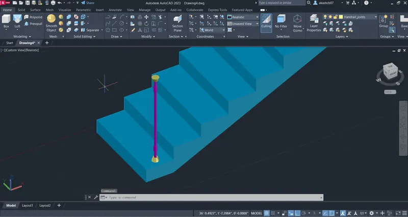
Step 3:
- Add the ballusters on the tread of the staircase upto top portion of the staircase.
- Then use the sweep by path command create a profile for handrail and add the handrail above the ballusters.
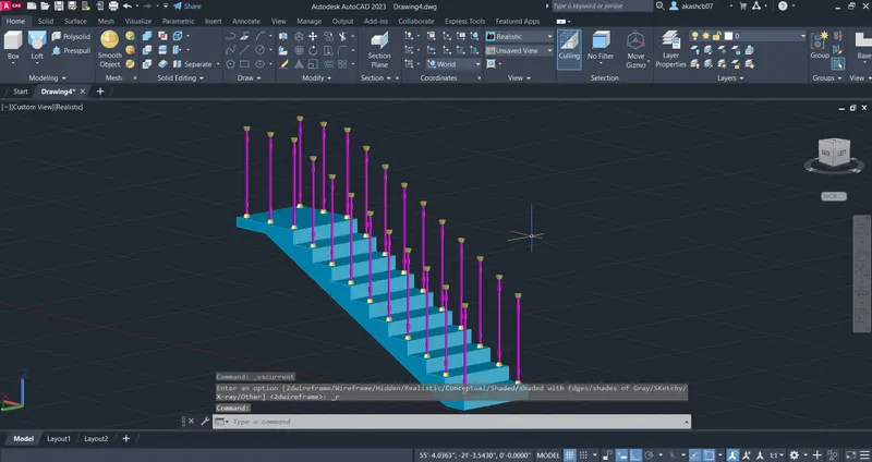
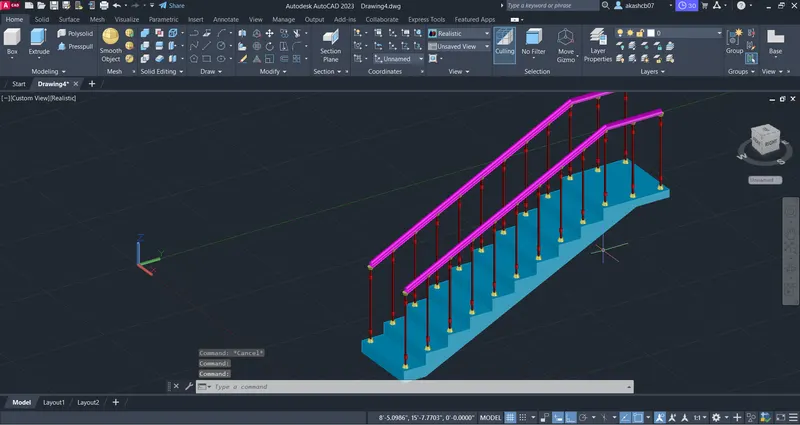
Result: Provide the Dimensions.
Q.4 Ans
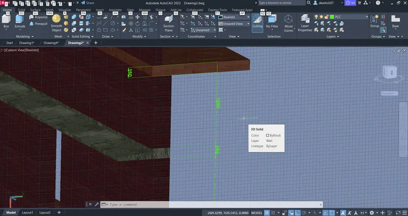
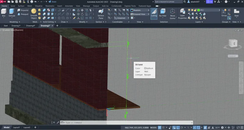
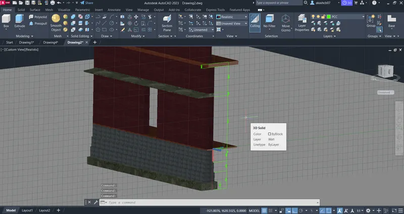
Aim: Create the 3D view of a Wall with spread footing.
Procedure:
Step 1:
- All the dimensions are in Milimeters so select the Decimal unit.
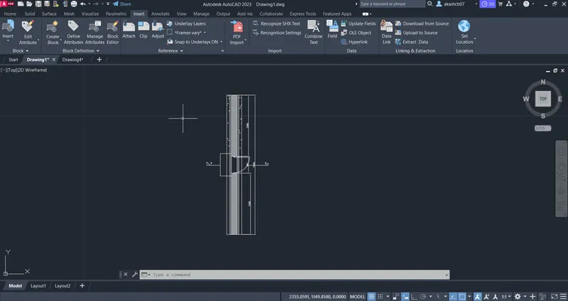
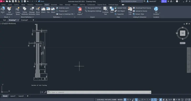
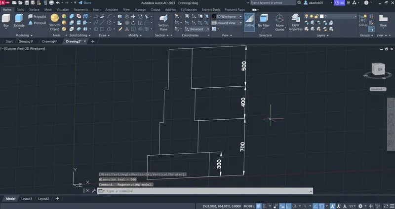
- Draw the line plan and section of the Wall.
- Use the required commands for drawing the lineplan.
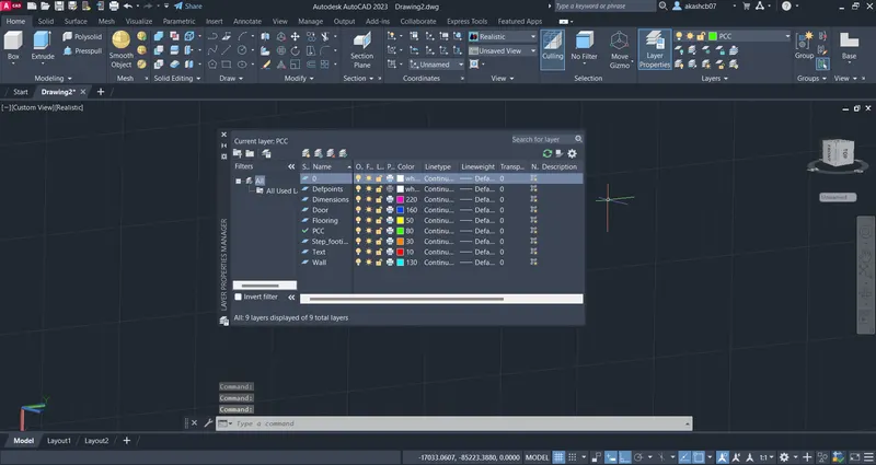
- Create the layers for PCC, Step footing, Walls, Flooring etc.
- After creating the lineplan change the workspace from 2D drafting to 3D modelling.
- As entering in the 3D modelling use the view cube for change the various views.
- Then use the Extrude command or use presspull command to create a Wall length.
- Provide width for wall length is 7500mm.
- Create a section of PCC and step footing.
Step 2:
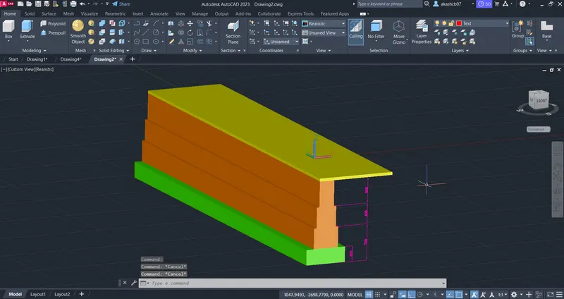
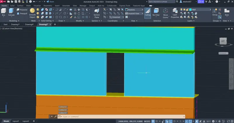
- Apply the layers to the different parts of the structure with different colour.
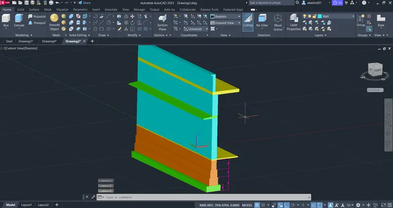
- Provide opening for the door of 900 x 2100 mm.
Step 3:
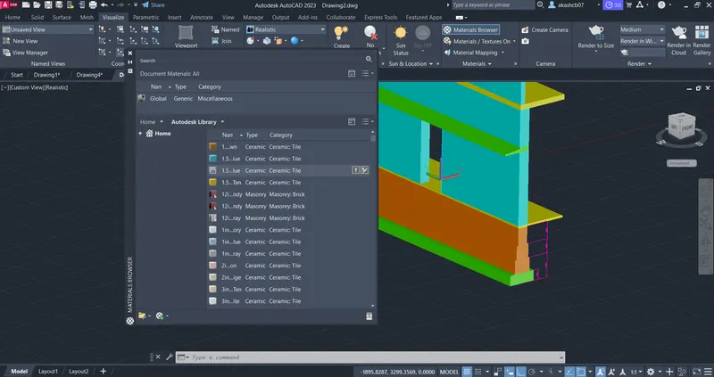
- Go to material browser and assign materials for all the parts of the structural section.
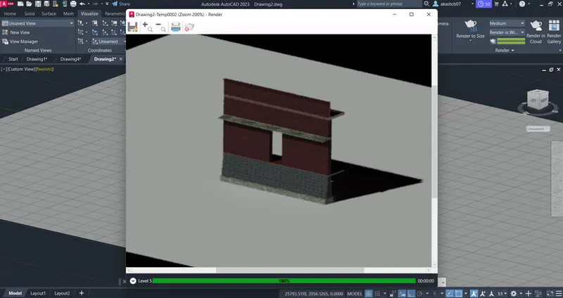
- As I am added the bricks to wall, concrete for PCC and stone material step footing and wooden flooring.
- Use rendering effect for take a actual view of the section.
Result: