To calculate dead and live load for industrial steel structures and to apply them using TSD
Q.1 Ans
Aim: Calculate dead load in design report based on IS code and apply dead load on the model.
Given Data,
- Finishes of 50mm
- Slab as per design
- Brickwall 150mm thickness
- Roofing load based on purlin size
- Ceiling loading of 0.3 kN per Sq.m
Procedure:
Step 1:
Load Calculation:
- Dead load = `1.2 kN//m^2`
- Finishing Load off 50mm = `0.05 xx 24 kN//m^2 = 1.2 kN//m^2`
- Brick wall load (Ground to First Floor) = `0.155xx20xx5.25 = 16.275 kN//m^2`
- Brick wall load (First to Second Floor ) = `0.155xx20xx6.8 = 21.08 kN//m`
- Roofing Load based on purlin size = `1.5 kN//mm^2`
- Ceiling load = `0.3 kN//m^2`
Step 2:
- To apply load create load cases for Dead load.
- Go to Load -> Structure -> Loadcases.
- Create load cases for Dead load, Imposed Load, Wind Load & Seismic Load.
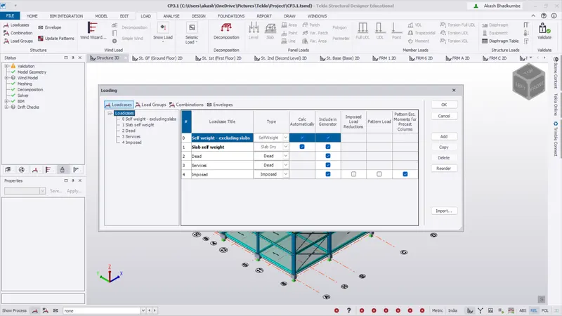
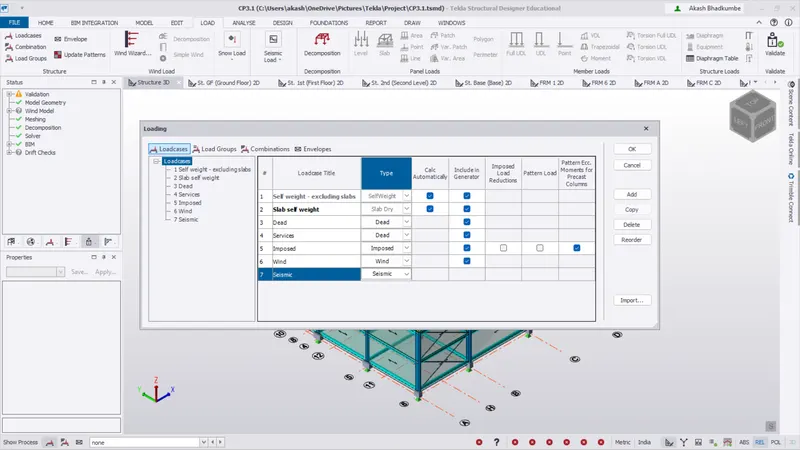
- Create load combinations for the load cases.
- Go to Load -> Structure -> Combination.
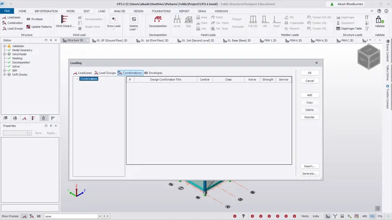
- Click on generate tab. Then click on next. It will automatically generate the load combinations, Service load combinations and National Horizontal Forces (NHF).Click on Finish & ok.
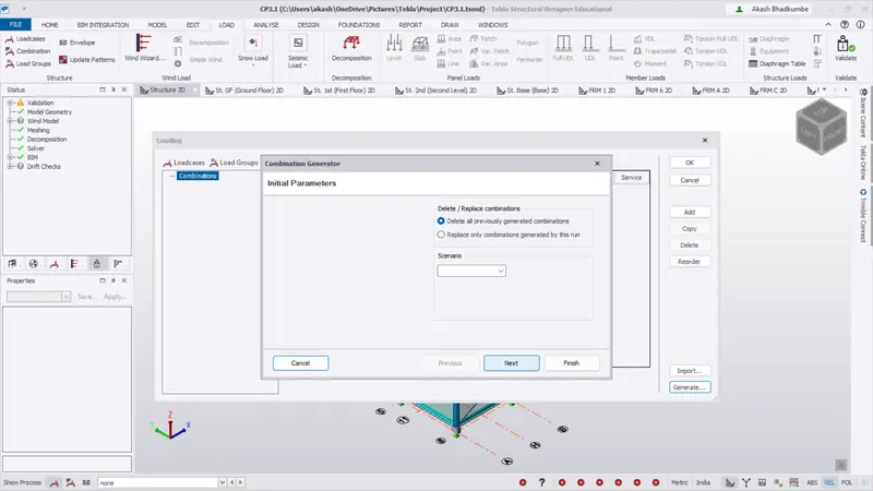
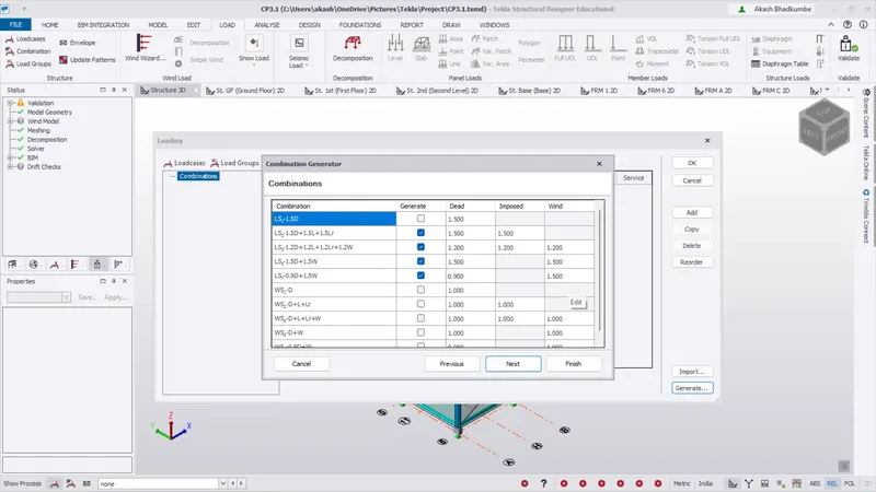
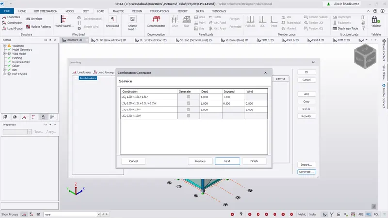
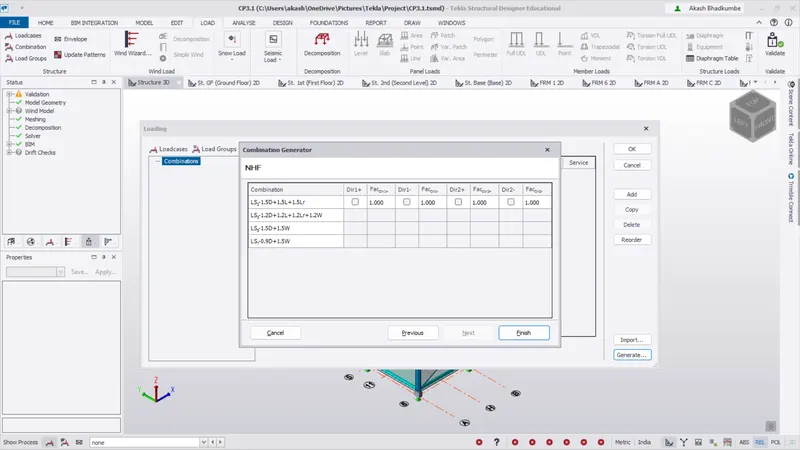
- All loadcases are generated now we have to apply the dead load.
- We are adding area load on slab. Select the load as Dead.
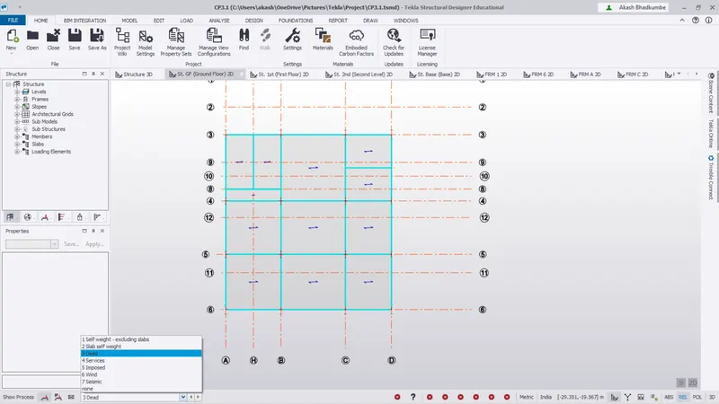
- To apply dead load on floor we will apply the area load.
- Go to Load -> Panel Load -> Area Load.
- Go to ground floor and in properties browser change the load value as `1.2 kN//m^2`.
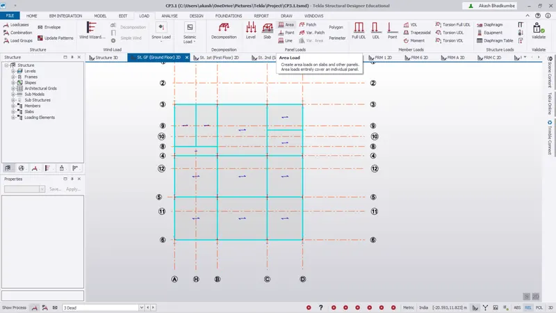
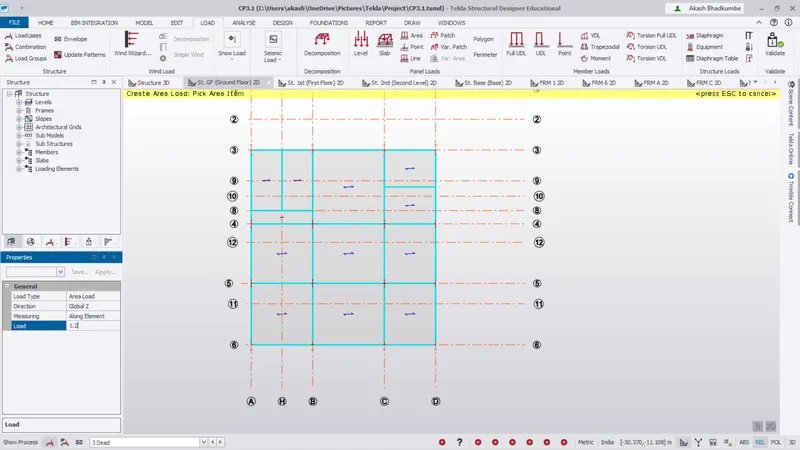
- Click on the floor area so the applied floor will change in green colour.
- Select one by ony all the floors and add the loads carefully on floor.
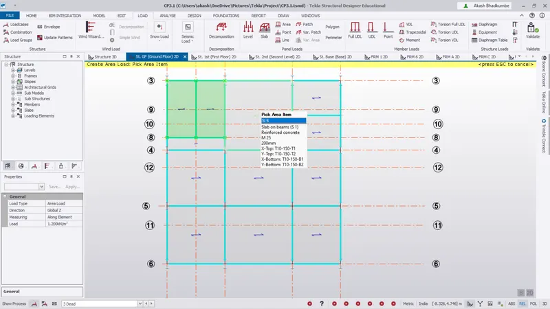
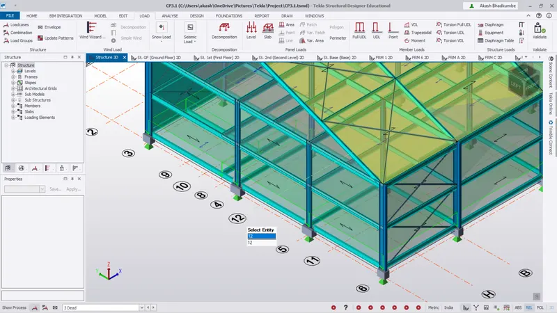
- Similarly apply the load on first floor and on second floor.
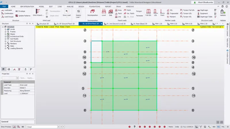
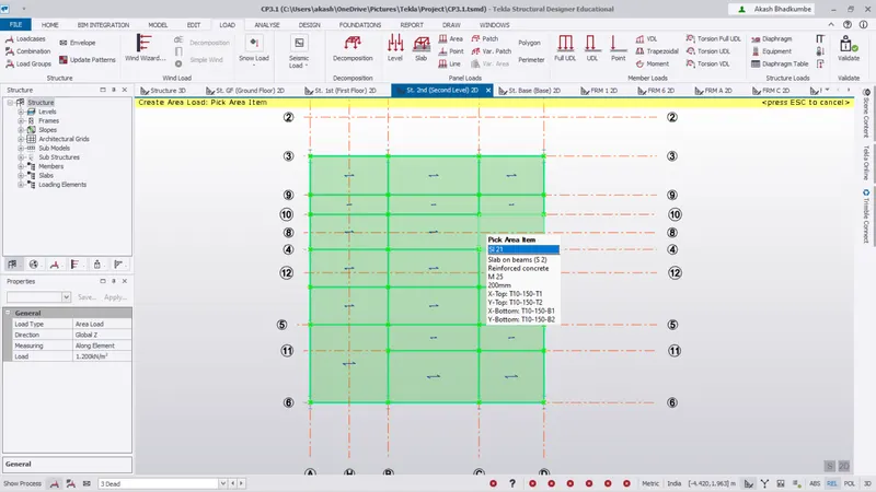
- Area load is added on all the floors.
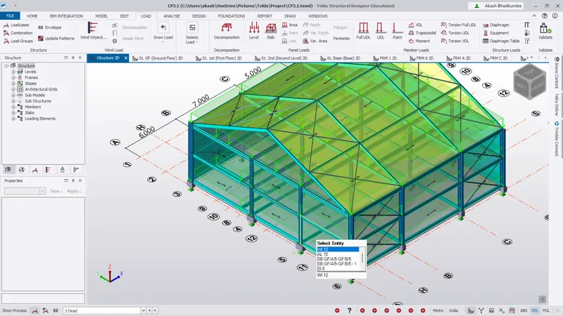
Step 3:
- To apply the member load go Load -> Member load -> Full UDL for brick wall.
- Change the load value as `16.275 kN//m^2`.
- Select all the members to apply member load.
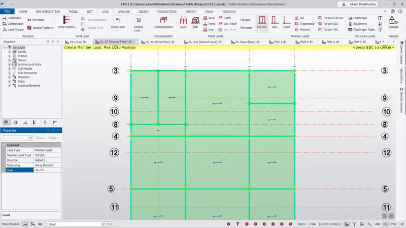
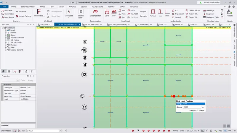
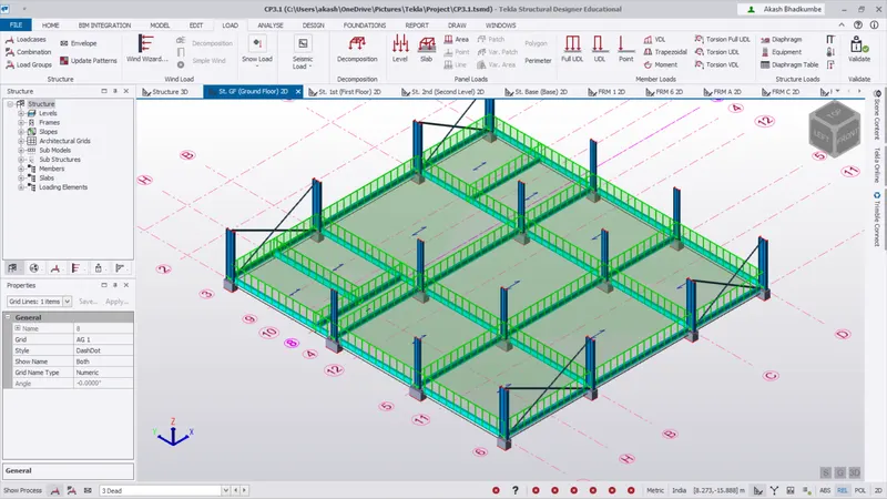
- Similarly add the load for all floor with respected loading values.
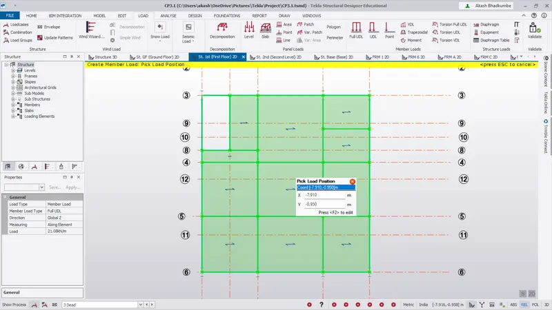
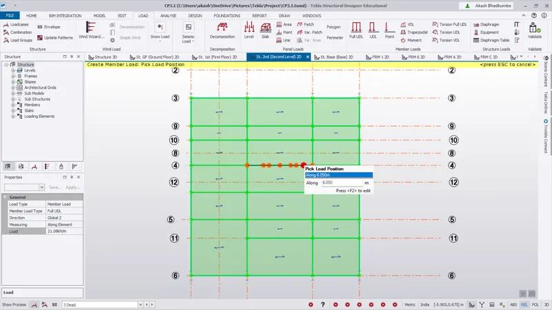
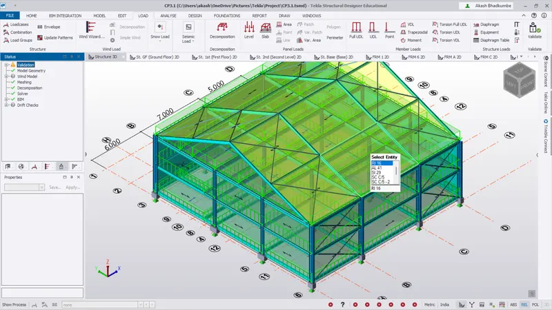
- Click on validate and check that there is no error in the loading.
Step 4:
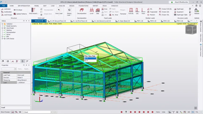
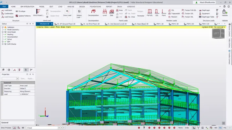
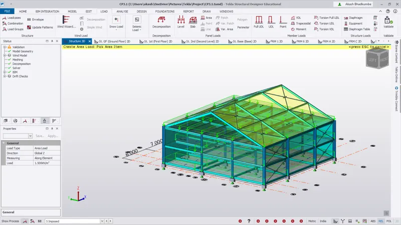
- Go to Load -> Panel Load -> Area load. Select the roof area for roof loading.
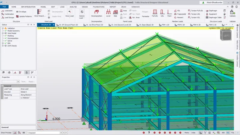
- Add the load on roof by using area load. Select all the roof one by ony and add the roof load.
- Apply the loading value as `1.5 kN//m^2`.
Conclusion:
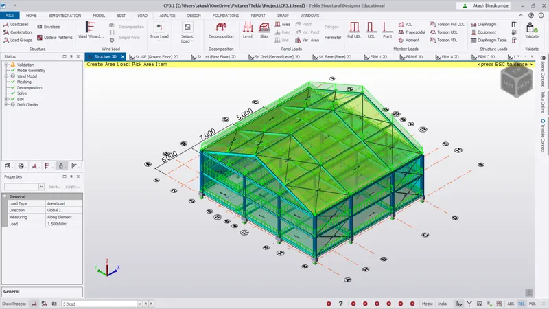
- The Dead load is applied on Slab area, Roof area and member. There is no error in application of dead load.
Q.2 Ans
Aim: Calculate the live load in design report based on IS Code and apply live load on the model.
Procedure:
Step 1:
- We have to apply a Live or Imposed load to structure.
- As per `IS 875 (Part-2):1987, Tabl e - 1,Clause 3.1,3.1.1 & 4.1.1` there are different values for different room parameters`
- The load values are specified in `Tab l e-1` are equivalent uniformly distributed loads on the plan area and provide for normal effect of impact and acceleration. They do not take into consideration special concentrated loads and other loads.
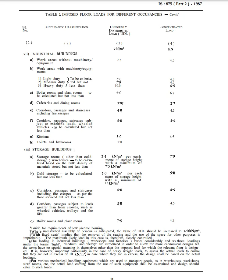
- To add live load on floor change the load type as Imposed.
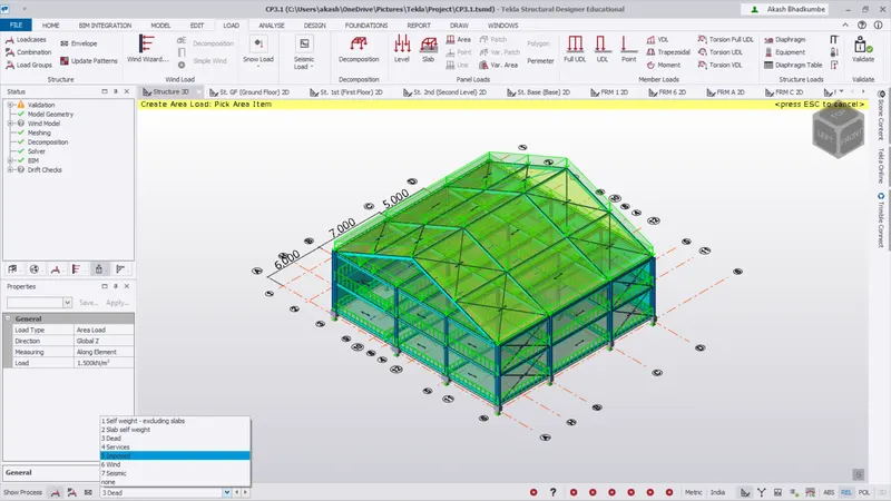
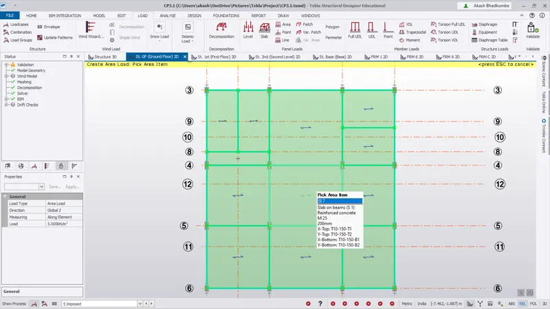
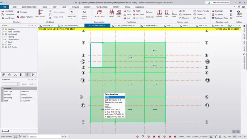
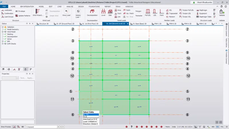
- Then go to Load -> Panel load -> Area loading. Change the load value from properties browser.
- Take different values as per different rooms and apply loads.
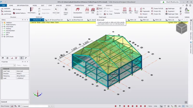
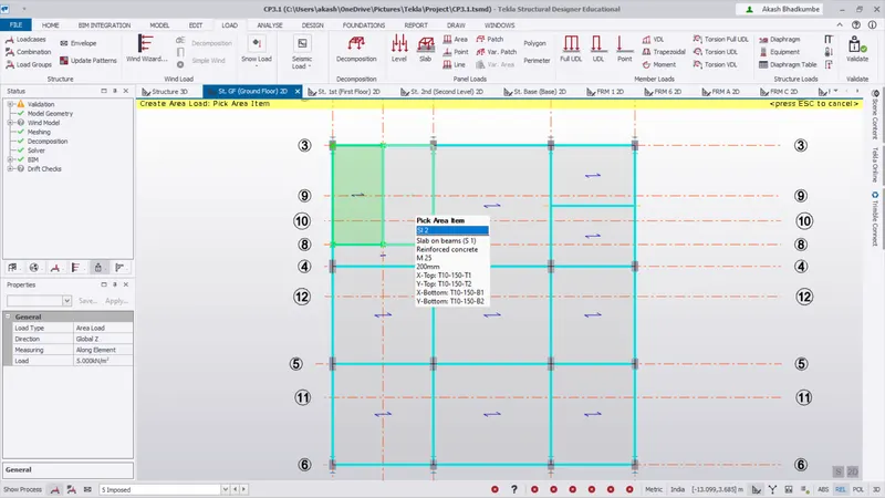
- Similarly add load for all the floor area at every level.
Step 2:
- As per `IS 875 (Part-2):1987, Tabl e -2, Clause 4.1`
- Sloping roof with slope greater than 10 degreea the value of iposed load will be `0.75 kN//m^2`
- Go to Load -> Panel Loads -> area load and check the value of loading will be `0.75 kN//m^2`.
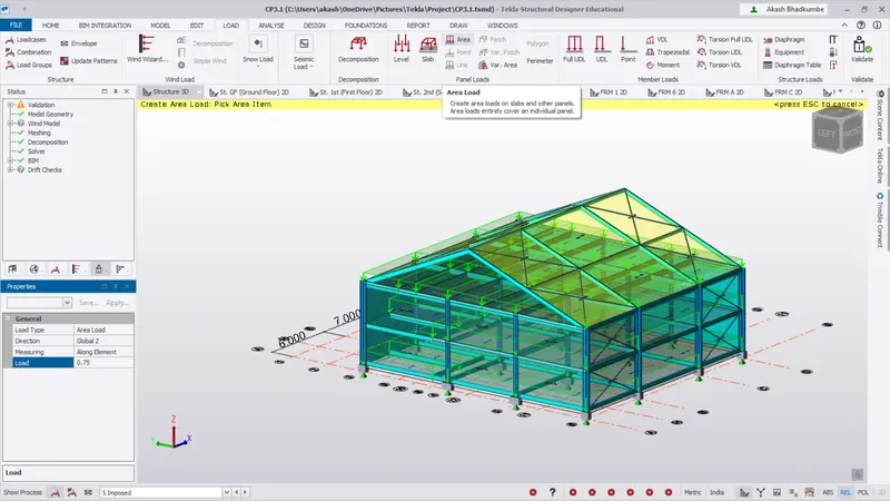
- Add loading on roof.
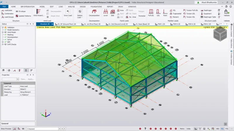
Conclusion:
- The Live is added on all the floor with respected room loading values.As well as we applied the Imposed loading on roof too.
Q.3 Ans
Aim: Generate a calculation for 5T crane loading based on following inputs
- Centre to centre of wheel=10m
- Weight of crab = 40 kN
- Number of wheels = 4
- Wheel base = 2m.
Procedure:
Step 1: Given data,
- Lifting Load `= 5T = 50kN`
- Centre to centre of wheel = `10m`
- Weight of Crab = `40kN`
- number of wheel = `4`
- Wheel base = `2m`
- Weight of trolly car = `10kN`
- Hook Approach = `1m`
Step 2: Maximum point load on crane,
Maximuma point load on crane = crane capacity + weight of trolly
= `50+10 kN`
= `60 kN`
UDL = (Self weight of crane)/(Distance between gantry rails.)
= `40/10`
= `4 kN//m`
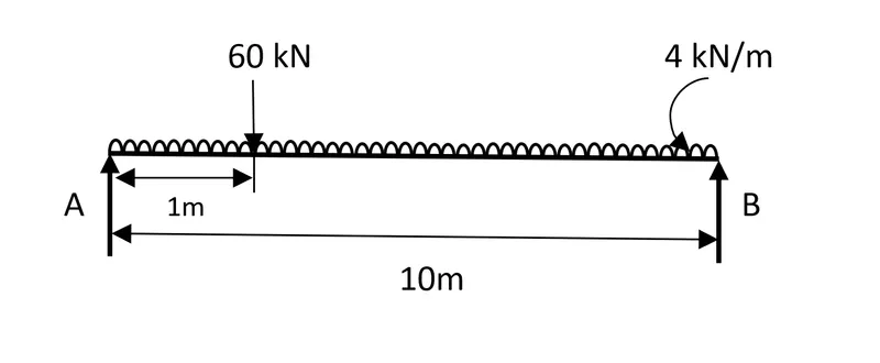
Moment at A:
`sum M_A =0`
`= 60xx1+4 xx10xx(10/2) - R_Bxx10`
`therefore R_B=26 kN`
Vertical forces :
`sum F_y= 0`
`R_A+R_B-60-4xx10=0`
`R_A=60+4xx10-26`
`therefore R_A=74 kN`
Maximum Bending Moment:
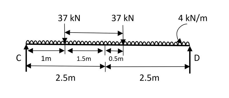
Assume the weight of gantry girder `= 1.2 kN//m`
Self weight of Rail `= 0.3 kN//m`
Total Self weight is `= 1.5+0.3 kN//m=1.8 kN//m`
Moment at C:
`sum M_C=0`
`(37xx1)+(37xx3)+(4xx5xx(5/2))-R_Dxx5=0`
`R_D=39.6 kN`
`sum F_y=0`
`R_C+R_D-37-37-4xx(5/2)=0`
`R_C=44.4 kN`
Bending Moment uder wheel load due to live load:
`R_Dxx2=39.6xx2=79.2kN//m`
beding Moment due to impact = `0.1 xx 79.2 = 7.92 kN//m`
Total bending moment due to live load and impact load = `79.2 +7.92 = 87.12 kN//m`
Bending moment due to dead load = `(Wl^2)/2 = (1.8xx5xx5)/8 = 5.625 kN`
Maximum Bending moment = `87.12+5.625 = 92.745 kN//m`
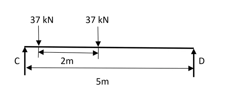
Maximum Shear Force:
`sum M_D=0`
`R_Cxx5 - 37xx5-37xx2.5=0`
`R_C= 55.5 kN`
Hence the Maximum shear force due to wheel load is = `55.5 kN`
Lateral Forces:
Lateral forces transeverse to rails = 5% of the weight of crab and weight lifted
`= 0.5 (40+10) = 2.5 kN`
Lateral force on each wheel F1 will be = `(2.5/2) = 1.25 kN`
Maximum horizontal reaction due to lateral forces by proportion at C.\
= Lateral force x reaction at c due to vertical load / Maximum wheel load due to vertical load
= `1.25 xx (44.4/37) = 1.5 kN`
Horizontal reaction due to lateral forces by proportion at D.
`2.5 - 1.5 = 1 kN`
Bending Moment due to lateral load = `1.25/37 xx 55.5`
= `1.875 kN//m`