Week 6 - Creating connection for Rear door
Rear Door Connections in ANSA
INTRODUCTION
In order to enter and depart a vehicle, a car door is a sort of door opening that is normally hinged on its front edge, though occasionally attached by other mechanisms like tracks. For vision from within the car, side windows are frequently integrated into doors, which may also be locked to secure the car. Car doors can be opened manually or with the vehicle's power assist. Small cars, high-end autos, and customized cars may all have powered or power doors. Typically, a car has two different kinds of doors: front doors and rear doors. To prevent unwanted entrance from the outside, the majority of car doors are fastened shut to the vehicle body using latches that can be locked. The majority of car doors have windows, and most of them can be opened to different degrees. Vehicle doors frequently have brakes, sometimes known as "stays," that limit how far the door may open and slow the door down right before it closes. The rear door that we are using in this model is a conventional door. A conventional door, also known as a regular door is hinged at the front-facing edge of the door, and so allows the door to swing outward from the body of the car. These doors are relatively safe, in that if they are opened during the forwarding motion of the vehicle, the wind resistance will work against the opening door, and will effectively force its closure.
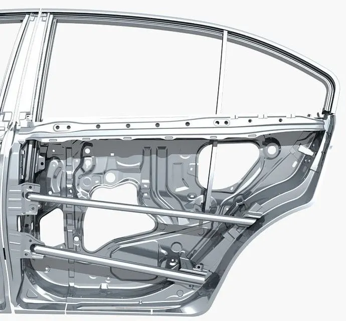
Figure-1: A frame of the rear door is displayed in this figure
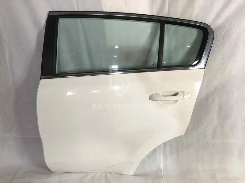
Figure-2: A modern rear door of the car is shown here
AIM
For the given Rear door FE model, create and Apply different PIDs for different components. Perform suitable connections. (No thickness needs to be assigned to FE as the intention is just to deploy connections)
PROCEDURE
The entire process is divided into many steps and completed in the following order:
- Since the initial steps of geometrical checks, mid-surface extraction and meshing are already done for the given model so we proceed with the final phase which is connections. But before proceeding further we have to divide all the different parts of the door model into separate PIDs. Doing so it will make our work easier to generate connections in specific locations.
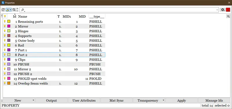
Figure-3: PIDs set for all parts of door and connections
- After setting up PIDs we proceed with connections of each type in order to connect all PIDs together so that we can simulate the whole model at later stages. The forces and other factors need to pass through the FE via numerous connections for the whole model. For every connection, we either create a curve or a point that defines an entity of the connection in the model browser. The specific curve or point that is created on the edges or around the edges is converted into a spot weld, spot line, bolt or seam line according to the connection type. We use various buttons in the Assembly toolbar to perform and manage connections. We use RBE2 (Rigid body element form 2) or RBE3 elements using the Nastran deck in the FE representation of this model.
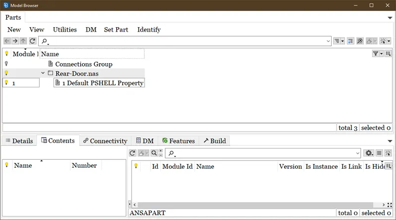
Figure-4: Connection entities are set in a new group
- So we initiate with the C-Bush connections between the mirrors and the other door parts near it. This connection is used between parts which need a very lengthy and impact-proof connection. Here we create a curve on the edge of one surface and convert it into a spot line using the convert option in the Assembly toolbar. After that, we translate it in between these connecting parts. Furthermore, we select the spot line with the connection manager and assign properties, spacing value, search distance and P Bush ID of C-Bush. We choose RB3-CBUSH-RB3 in FE representation for this connection• Apply and realize the connection; if the status reads "OK," the connection has been established. The various parameters supplied to the C Bush connection need to be checked again if any errors are made. In the properties list, the PID for the C bush connection will be designated as P Bush.
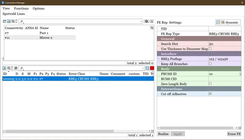
Figure-5: C Bush creation in the connection manager
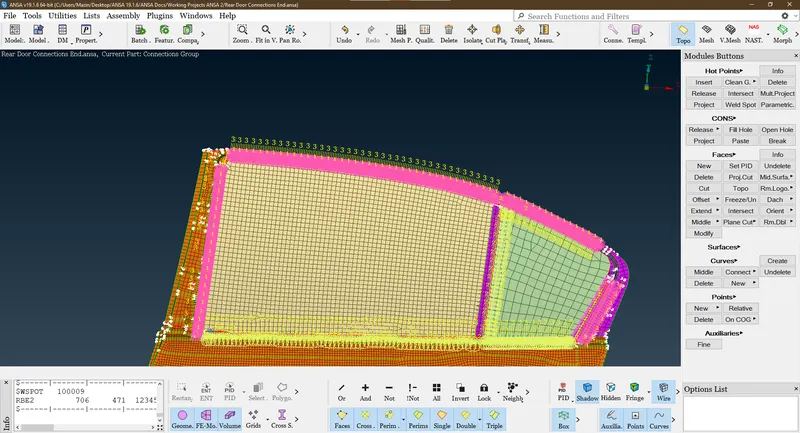
Figure-6: All C Bush connections established in the rear door model
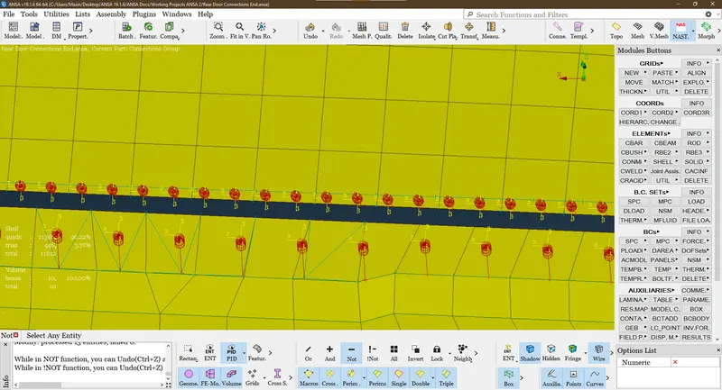
Figure-7: C Bush having a damper and spring attachment in zoom view
- In locations where all DOFs (Degree of Freedoms) are constrained except one rotatory DOF, whichever is in line with the screw axis of the bolt, we advance employing bolt connections. We use 2 ways either directly creating a 3D point in the Points group of the Topo deck and progress with the common method already discussed or we can create a spider. The spider is created by choosing the RBE2>Many nodes button in the elements group of the Nastran deck. And the nodal connection between the spiders of two holes is given between them by choosing the RB2>Two nodes button. The rotatory axis which is not constrained or dependent is eliminated in the CM parameter of the established nodal connection. The bolt connection has been established also between the hinge and supports in this model and at various holes of the outer body of the door and other parts parallel to each other.
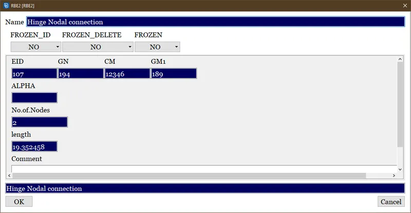
Figure-8: In this figure, the rotatory Y-axis designated as number 5 is eliminated in the CM slot because it forms the screw axis. CM parameter includes all axis that is constrained.
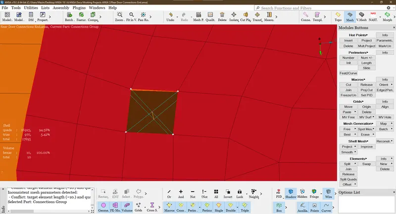
Figure-9: Bolt connection formed by spiders
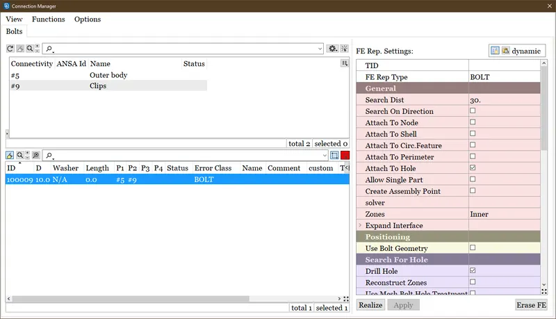
Figure-10: Bolt connection generated in the Connection manager
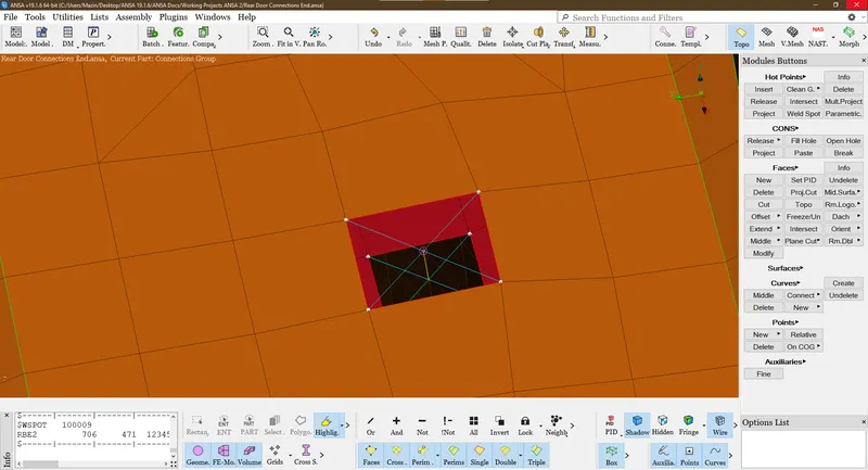
Figure-11 Bolt connection created using 3d point method
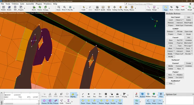
Figure-12 Bolt connection generated between hinges and support
- Henceforth we deploy seam weld connections in places where the surface area is more or a line of contact exists between two parts. We generate a curve in this connection and convert it into a seam line with the aid of convert in the Assembly toolbar. We provide necessary values to various parameters used in this connection in the connection manager. We choose Fe representation in this connection as an over-lap shell for parallel entities and Y-joint for perpendicular entities.
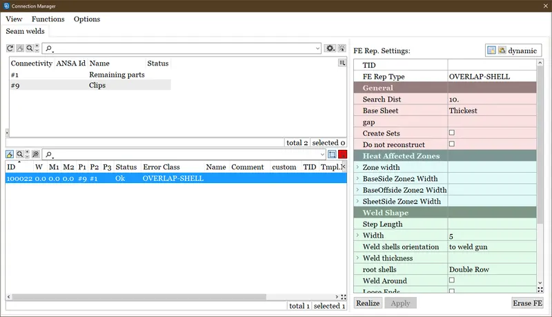
Figure-13: Seam weld generation in the Connection manager
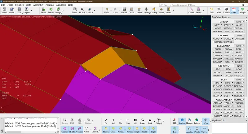
Figure-14: Overlap shell seam weld on the cylinder rod
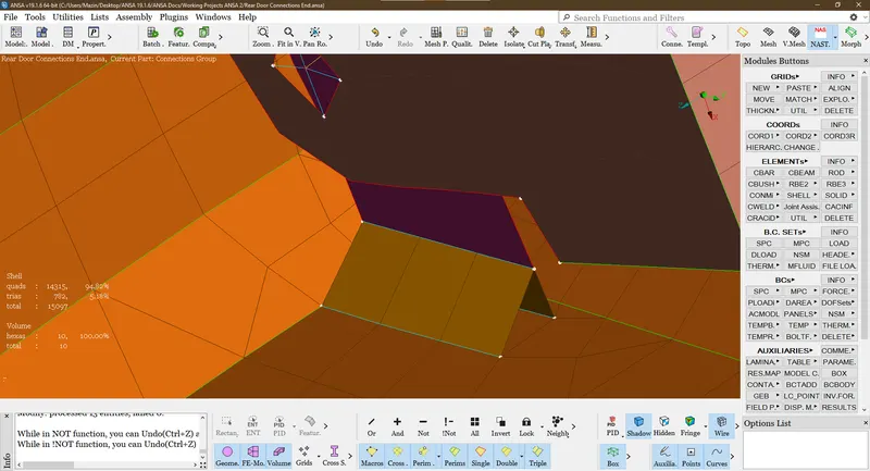
Figure-15: Overlap shell seam on the support and hinge
- Nevertheless, we devised spot weld which is used in areas where the point of contact exists between two entities. A 3D point is created at the point of contact on the 2D quad element of one entity and converted to spot weld by using convert in assembly toolbar. After that, we provide respective values to certain parameters in the connection manager. We choose RB3-HEXA-RB3 as FE representation and allocate P SOLID connection ID while deploying a spot weld connection.
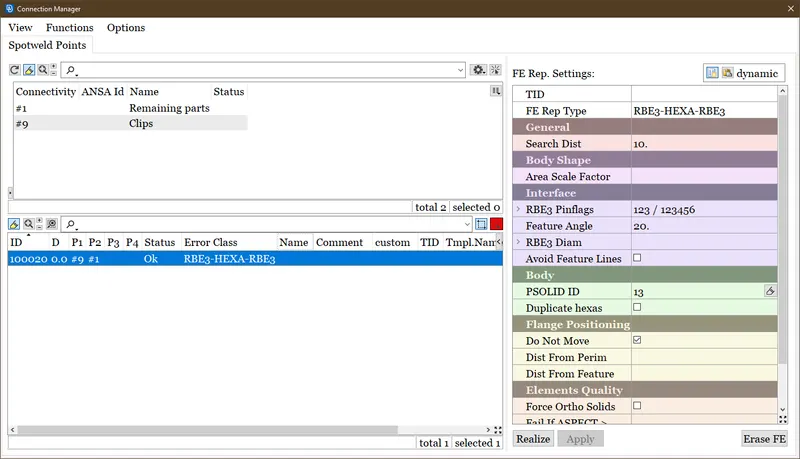
Figure-16: Spot weld generation in the Connection manager
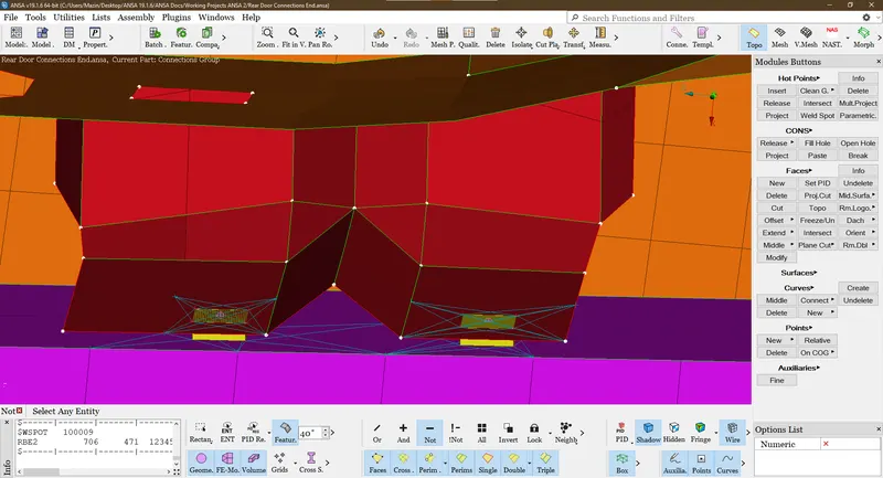
Figure-17 Spot welds established on surfaces having a point of contact.
- Finally, we inspected and re-checked all connections again to obtain error-free simulation in later stages of FEA. We made sure that all parts are connected properly by using the Neighbor All option and some Boolean operations in the Focus toolbar. In the visibility toolbar, we can also check unnecessary connections or empty connections. After modifying all connections and arranging them in order we completed the process.
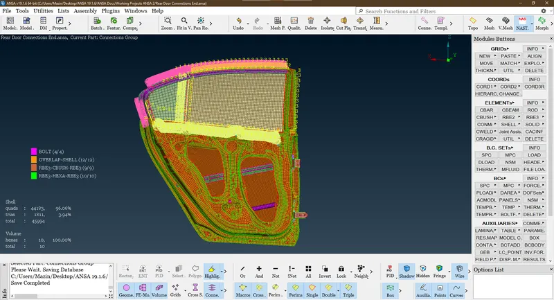
Figure-18 Overview of whole rear door model with connections portrayed in it
LEARNING OUTCOMES
- We explored new operation in pre-processing stage of FEA in ANSA which cleared concepts of force analysis and transmission.
- We learned a new technique to implicate mechanical design parameters into this model.
- A proper set-up to head start simulation post meshing on any model or n number of entities.
- The concept of rigid bodies and Nastran deck is put into application here in this model which gave a good insight of solvers used in FEA.
CONCLUSION
- We set PIDs for all parts of the rear door FE used in this model to make the connection process easier and quicker.
- We embed specific PIDs for a particular type of connection. Hexa elements got generated onto the FE elements of respective entities.
- Error-free connections are deployed in this model and arranged according to FE representation.
- The whole model is incorporated as one single entity in presence of all 4 types of connections used in this model.