Week-7 Head Impact
PROJECT-1 HEAD IMPACT
INTRODUCTION
Head injuries are one of the most prevalent forms of injuries in vehicle-to-pedestrian incidents, and they can result in death or long-term impairments. However, a detailed investigation of pedestrian head injuries in real-world incidents is lacking.
Head injuries are one of the most prevalent forms of injuries in vehicle-to-pedestrian incidents, and they can result in lifelong impairment or death. Typical pedestrian head injuries in traffic crashes include scalp injuries, skull fractures, and brain injuries, which can be categorized as focal brain injuries or generalized brain injuries.
The German In-depth Accident Study (GIDAS) pedestrian collision data from 2000 to 2015 were used. The vehicle model and impact speed, pedestrian gender, age and height, body region, severity level and source of injuries, and pedestrian-to-vehicle encounters were all documented for each instance in the database. The team documented all injuries and categorized them using the 2005 Abbreviated Injury Scale (AIS) system.
CAE development of the automobile body is used to optimize the design of the car body to meet pedestrian protection criteria and thereby prevent or decrease injuries caused after a collision using tools based on the Finite Elements Modelling (FEM) simulation method.
Pedestrian safety CAE is a component of car safety engineering from a crash standpoint. In pedestrian protection, we strive to cause the least amount of harm to the head, upper leg (thigh), and lower leg (including the knee) in the event of a collision with a human subject. These tests are typically performed at lower speeds of 20-40 kmph because accidents tend to result in more serious circumstances above these speeds because braking in the event of an accident frequently results in a collision at low speeds.
A children's head form model is supplied in this project. You must recreate a scenario in which this head form collides with a car bonnet. For the first situation, the bonnet should be considered a rigid wall, and an elastoplastic material card should be utilized when employing the meshed hood model. The head impact coefficient must be determined manually and with the assistance of LS-PrePost based on the simulation.
Existing NHTSA standards call for a 50th percentile male Head Injury Criteria (HIC). The biomechanical basis for HIC was evaluated for the 50th percentile adult male, and alternatives to this function were sought. While significant progress has been made in the ability of analytical finite element head/brain models to simulate the major injury mechanisms prevalent in brain injury, it was felt that using their results in this current proposed rulemaking action would be premature.
The HIC36 value was used to compute the average value of the Head Injury Criterion (HIC), which is based on the average value of acceleration over the most crucial part of the deceleration.
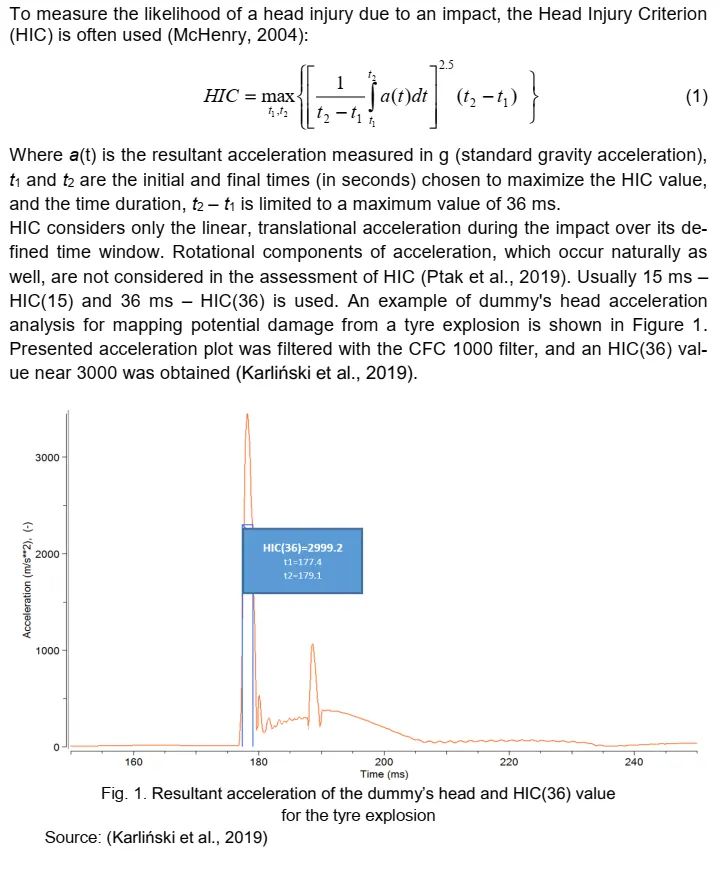
The goal is to run the Head Impact Simulation and determine the HIC value in the LS-PrePost.
- The keywords *INCLUDE, *INCLUDE_TRANSFORM, and *DEFINE_TRASFORMATION must be used to organize a multi-include file model in this project.
- The impact angle of the Pedestrian Head ranges from 35 to 75 degrees.
- Create a simple elastic material model for the provided simple head (meshed).
AIM
The report should contain the following,
- The impact simulation of a simple head impact with the Rigid wall.
- The impact simulation of the Headform provided with the Rigid wall with the Stress / Strain plots and acceleration plot.
- The impact simulation of the head form with the Hood with the Stress / Strain plots and acceleration plot. For the hood, you can use Aluminium.
- The Stress / Strain plot from the Rigidwall simulation should be compared with the Stress / Strain plot from the Hood Simulation and there should be a detailed explanation if there is any difference in the plots.
EXPLANATION
- The explicit analysis is employed in all three cases with various timestep sizes.
CASE 1: SIMPLE HEAD IMPACT WITH THE RIGID WALL
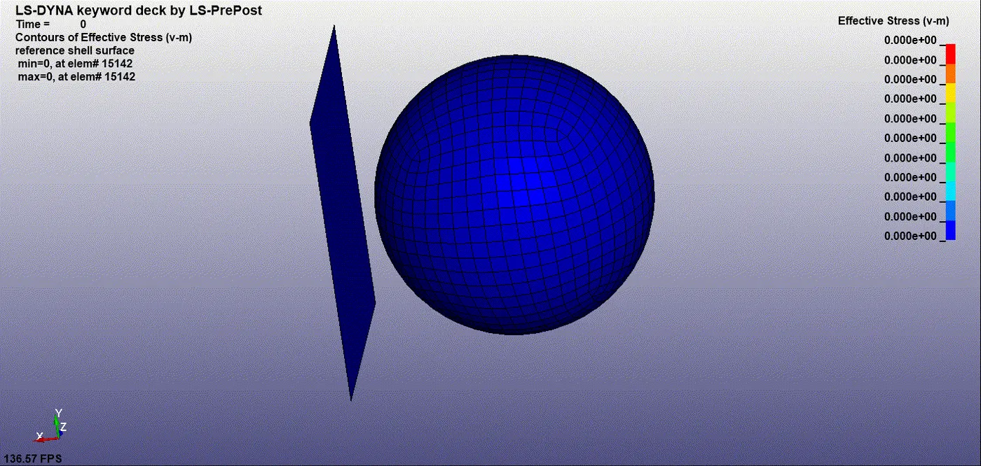
- The simple head model is first imported and tested to perform the final post-processing of the real headform model later on. It gives us a notion about the impact of the circular body on the flat body w.r.t various physical parameters.
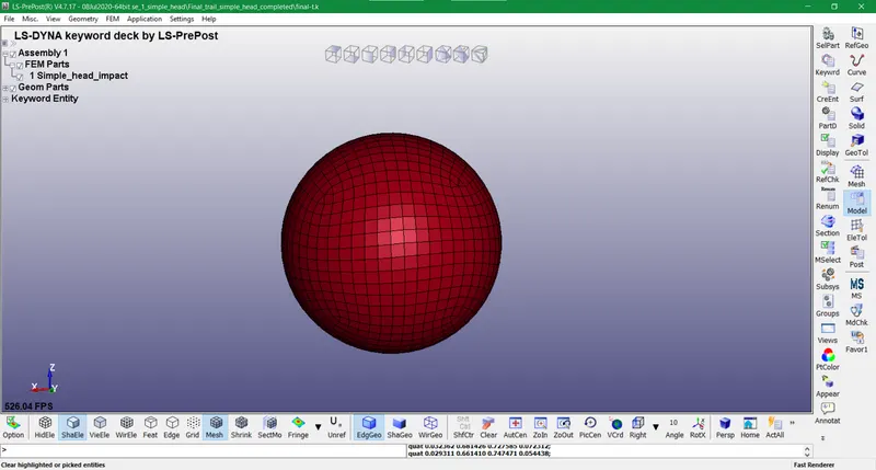
- The simple Mat 001 Elastic keyword with steel material is inputted initially with standard units as gm, mm, and ms.
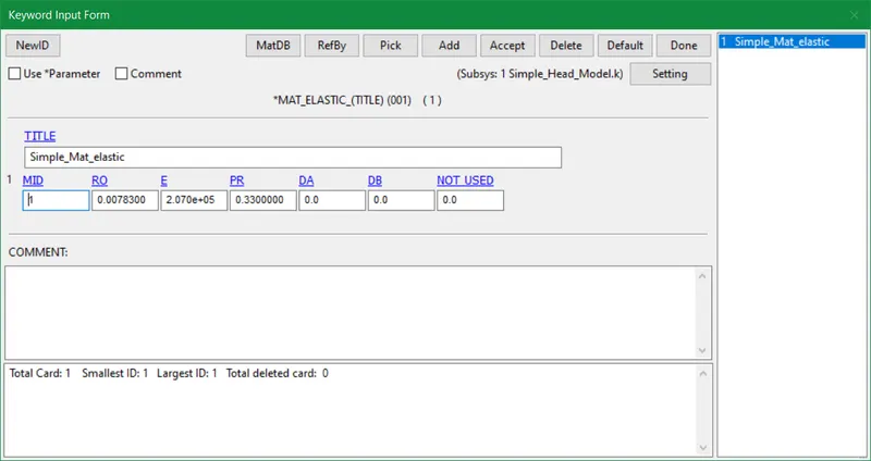
- This model has a circular shell component so we assume thickness as 1.5mm and use Elform 2 for better fast results.
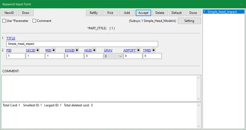
- The MID and SECID procured are assigned in a new part ID with the Part keyword.
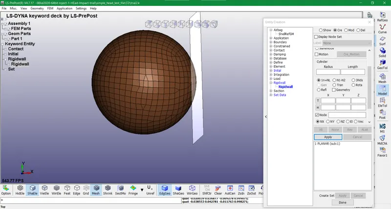
- The rigid wall is generated at a distance of 20mm in the direction of the x-axis w.r.t to the simple head model. Also, the normals of the rigid wall are thoroughly verified before proceeding to the next process.
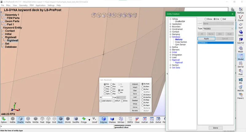
- In the database item, a history node is created in order to check for displacements, acceleration, and other quantities post-simulation.
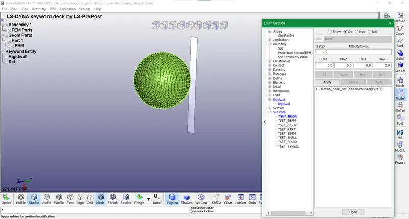
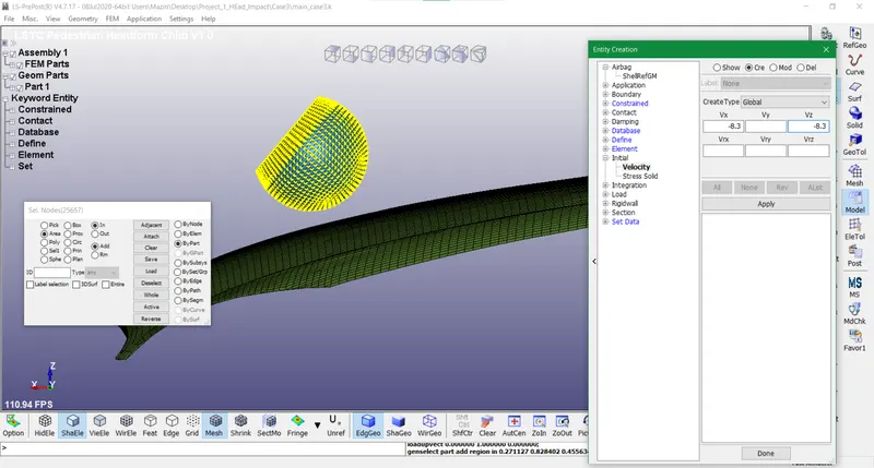
- The node set is created for the full shell part with the CreEnt tool in the Model option for designating a node set id for the initial velocity.
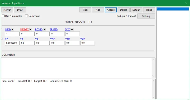
- The initial velocity used is 20kmph which is converted to 5.5 mm/ms in the x-direction. Since it is a linear velocity so we are putting it into VX only.
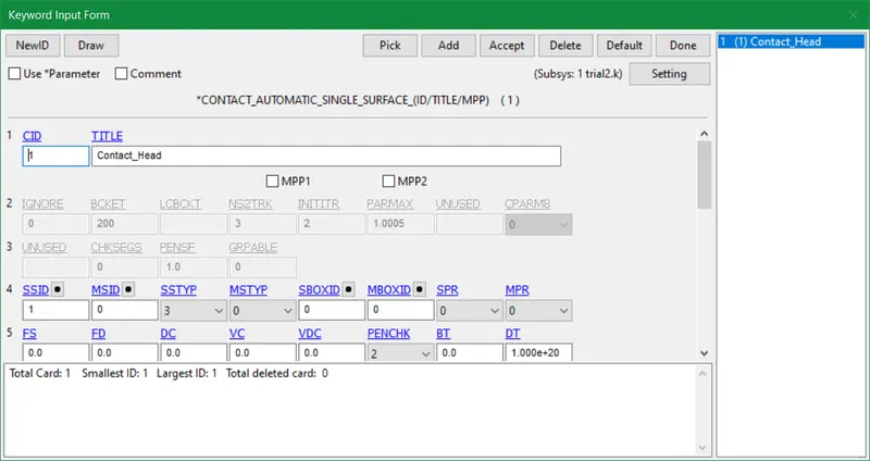
- The automatic single surface contact is provided to facilitate a self-contact for the simple head model. It means the simple head model is kept as a slave body and no master is placed as we are using a rigid wall.
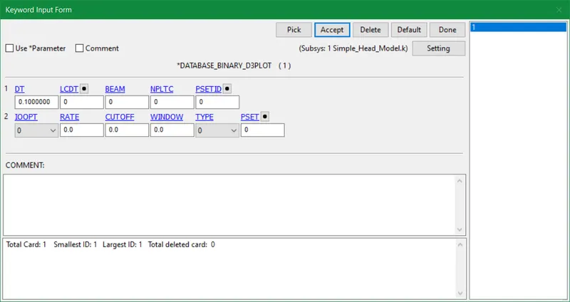
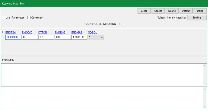
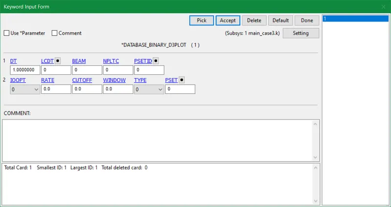
- The termination time is put as 5 and DT is kept as 0.1 for binary d3plot card. However, an ASCII database card is optional to derive energies, stresses, and other parameters.

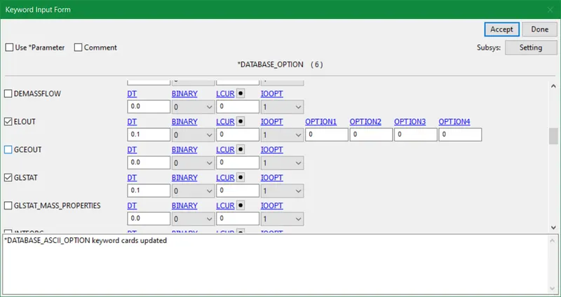
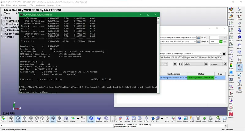
- Finally do the model checking and as a matter of fact, no errors were found. So save the file with the .k extension and run the simulation to obtain the binary d3plot output file.

CASE 2: HEADFORM IMPACT WITH THE RIGID WALL
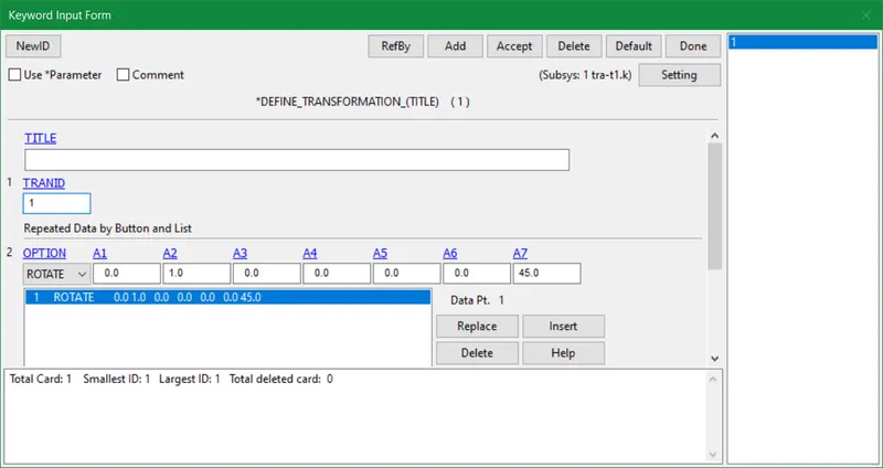
- In case 2 we will open a new file in LS-pre post and input the Define_Transformation card with given values. These values depict the rotation of the head form in the southeast direction in order to face the rigid wall downwards. The Impact angle of the Pedestrian Head can be placed between 35-75 degrees.
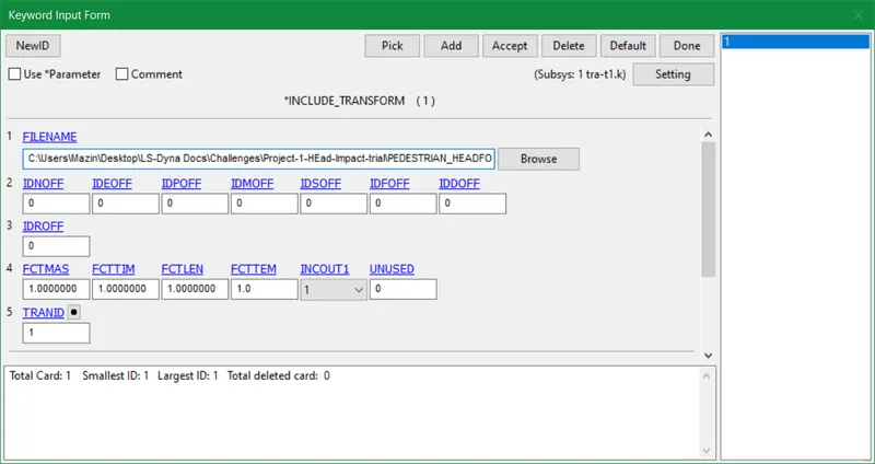
- The next step is to use the Include_Transform keyword and place the default head form file in the displayed slots. Afterward, save the file as a .k extension with the desired name in the same folder as the original head form file.
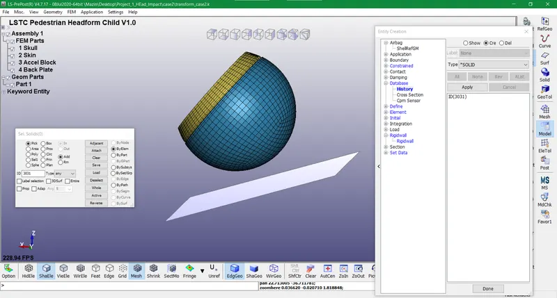
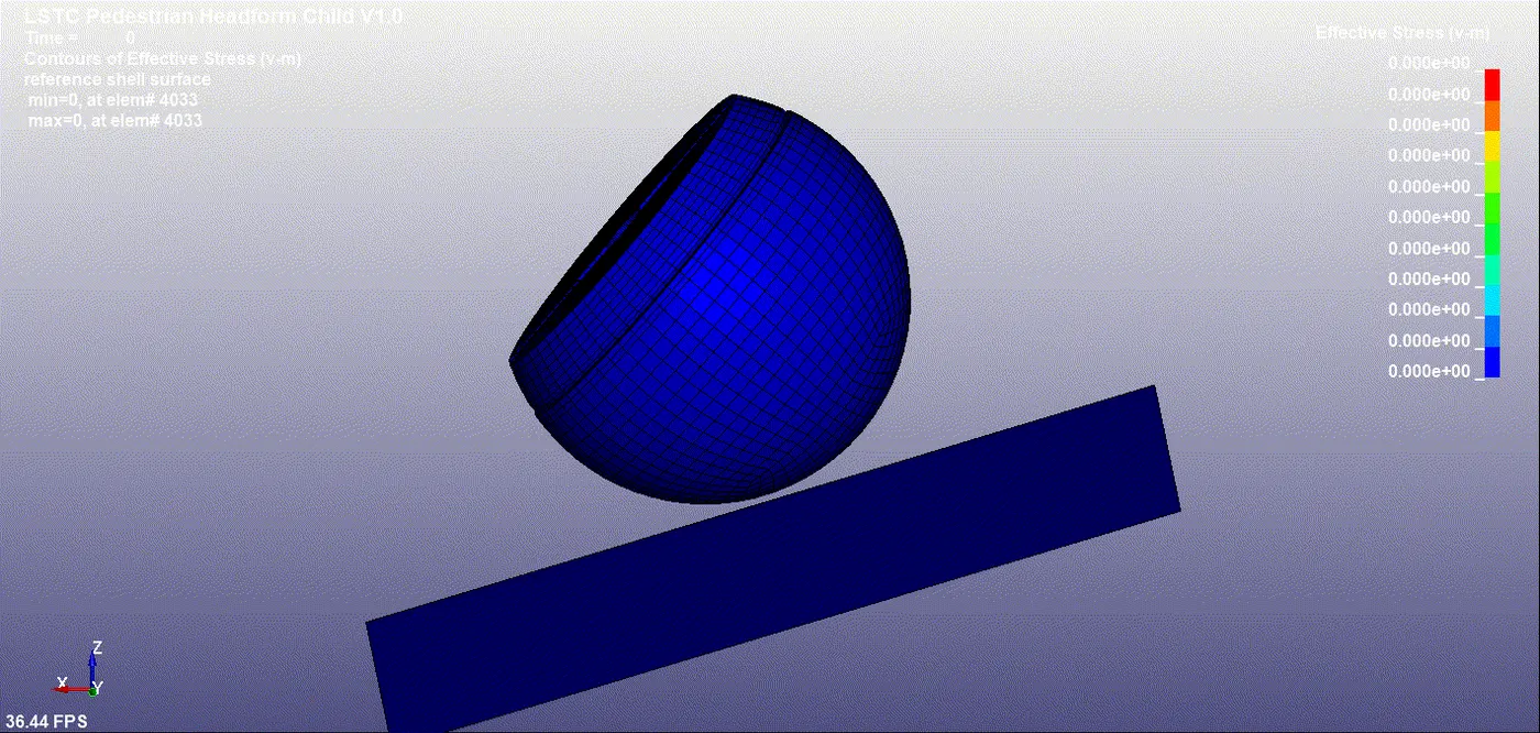
- So we will reopen the LS-pre post and open the newly formed file. The head form portrayed below will be rotated along the y-axis direction with an angle of 45 degrees. The head form model is comprised of 4 components viz. Skull, Skin, Accel block, and back plate. The skin i.e. blue color component will be the main part to be in contact with the rigid wall.
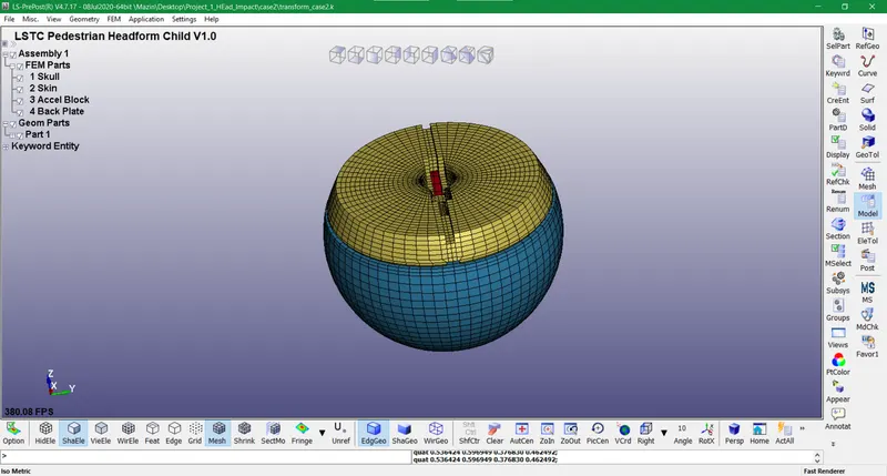
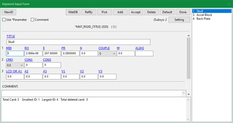
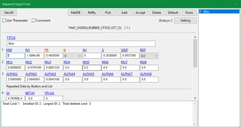
- The Material and section cards preserved in this model are by default so we won't make any alterations in them. Also, many more cards are added for respective assessments and evaluations that are also kept untouched.

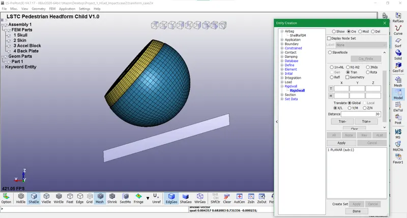
- So a rigid wall is created below the head form in an inclined manner just like a car hood pertaining to the floor. It is displaced at a distance of 30mm from the head form.
- A solid element is added to the history card in order to plot stress and strains post-simulation.
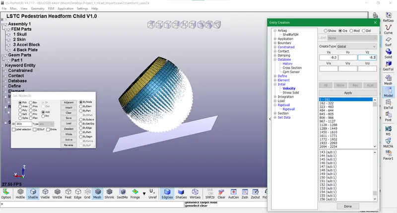
- An initial velocity of 30kmph is employed in this case which is equal to 8.3 mm/ms after conversion. The initial velocity vector is a collaboration of -x and -z directions w.r.t global coordinate system.
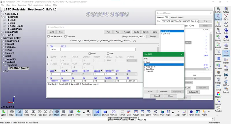
- The default contact between the skull and skin part as master and slave are kept unchanged.
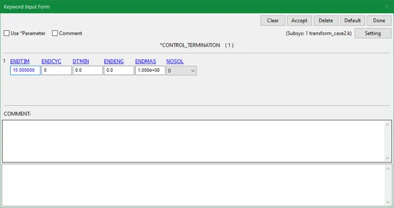
- The termination time is put as 15 in order to monitor the complete effect of stress and strains pre and post-impact. So time interval between outputs is inserted as 1 likewise.
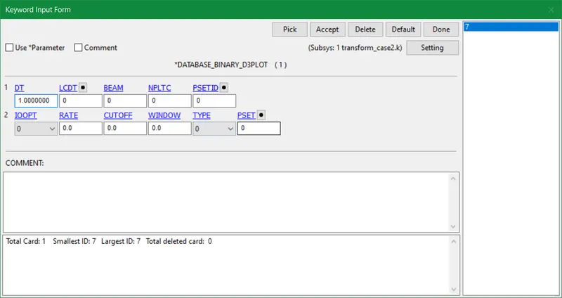
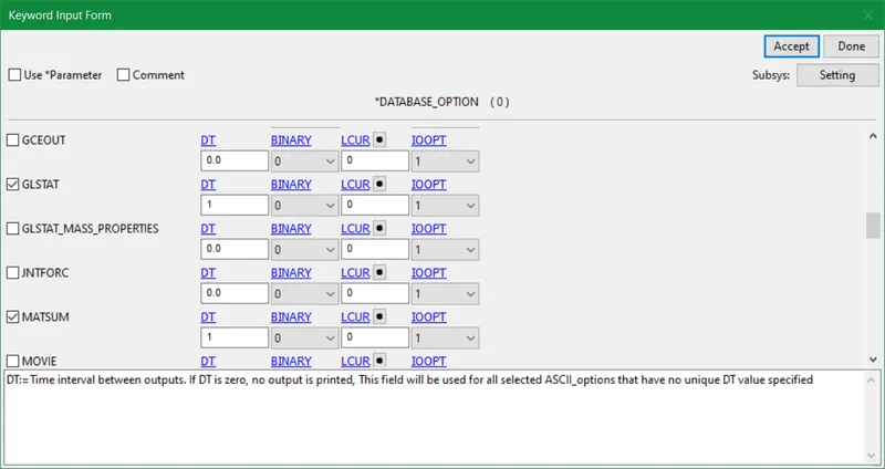
- Lastly placing necessary database ASCII items to plot the results for desired quantities.
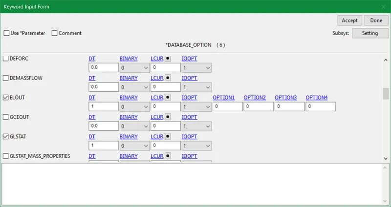
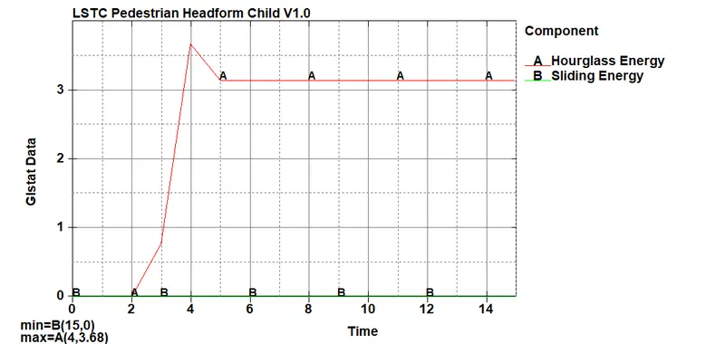
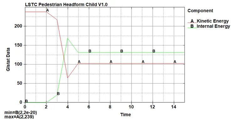
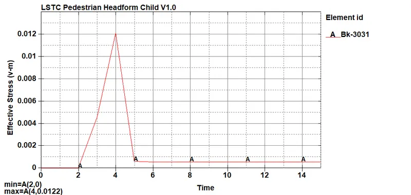
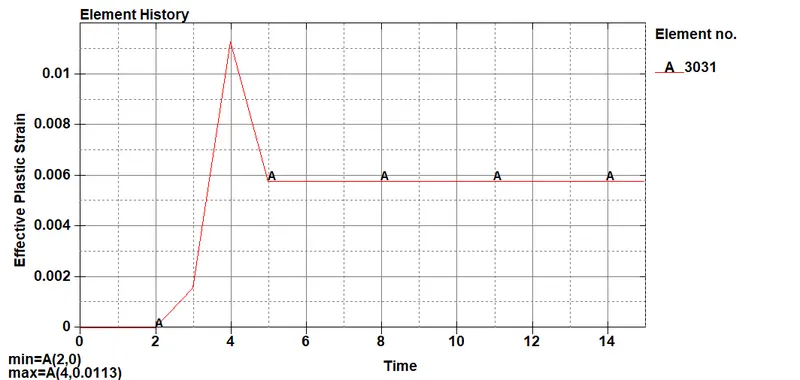
- Henceforth we ran the simulation and in the output simulation file, we noticed the plastic strain and concentrated uniform stress on the head form due to the infinite stiffness of the rigid wall. The essential results are computed and analyzed for further analysis up ahead.
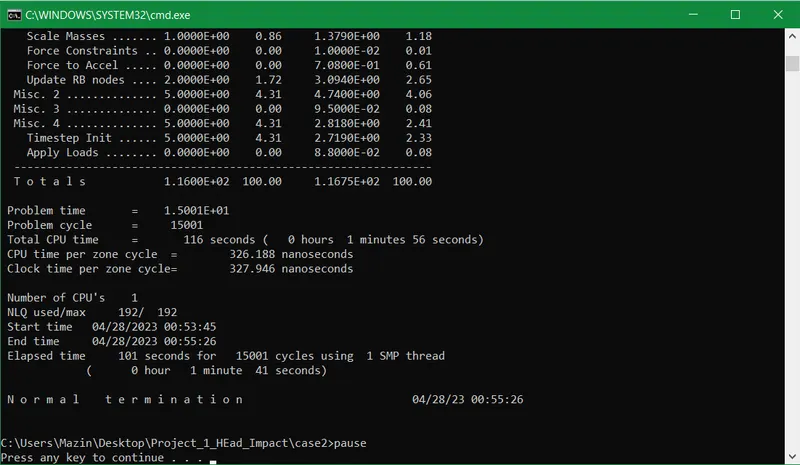
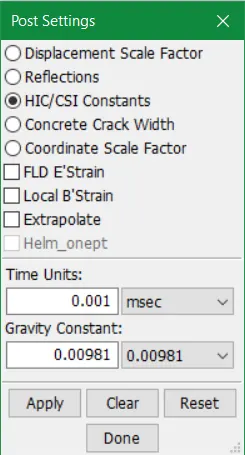
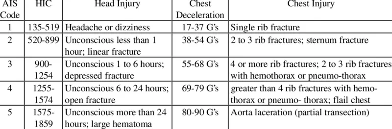
- According to the abbreviated injury scale, the HIC values show various results
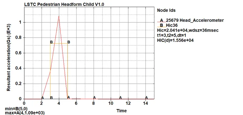
- The HIC36 value determined for this case is 1090 which comes under AIS 3
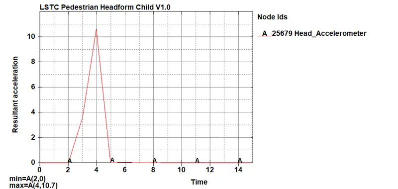
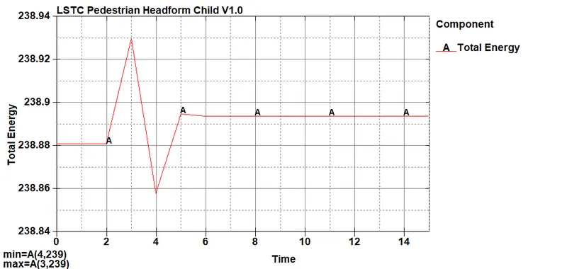
- The plots for energies, acceleration, stresses, and strains are portrayed below
CASE:3 HEADFORM IMPACT WITH THE HOOD
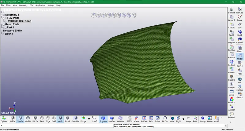
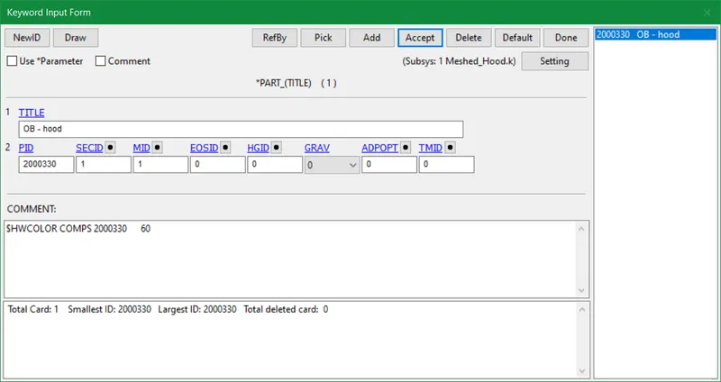
- In the final case instead of the rigid wall, we take the bonnet or hood of the car and do the testing. We follow all the steps like case 2 except we create a material card for the input hood file as given in the assignment. Also, we use the INCLUDE keyword and insert the newly formed hood file with the mat card.

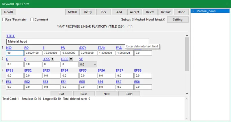
- The material used is aluminum with Mat_024 card and its physical properties.
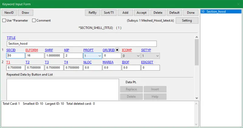
- The Elform 16 is used for faster analysis in the hood model. Since it is a sheet metal so a thickness of 0.75mm is inserted in this case.
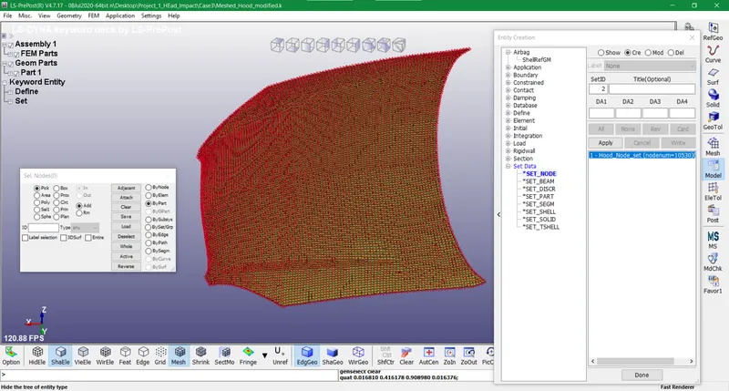
- The node set is created for the hood in order to create an interface as a contact between the hood and head form.
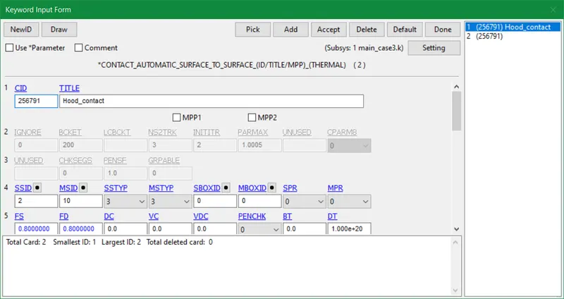
- In this case, the slave body is the skin part of the head form and the master body is the hood part.
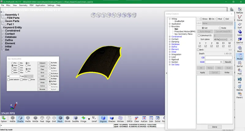
- The hood periphery is constrained by establishing SPC boundary conditions in all directions. The head impact shouldn't displace the whole hood that's why the outer nodes of the hood are constrained.
- The initial velocity, termination time, and database ASCII items are inserted just like in case 2
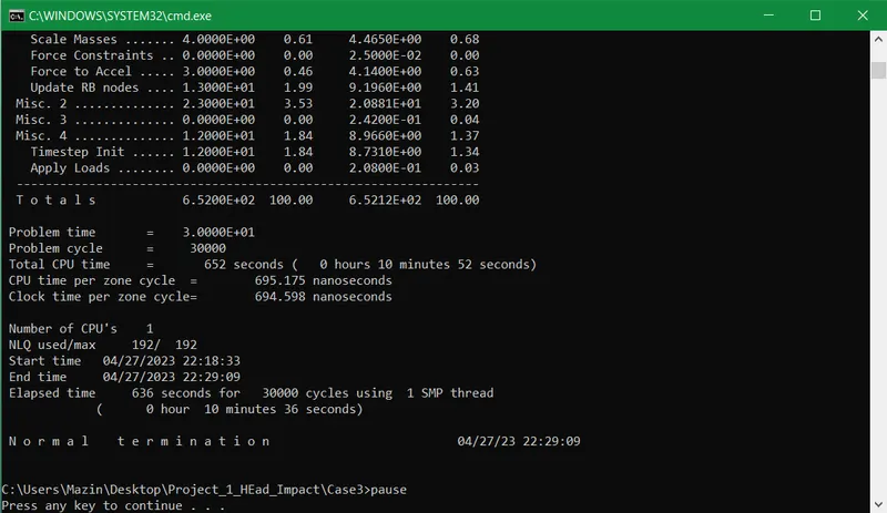
- The elapsed time was more in case 3 due to a large number of elements composed in head form and hood part. The top view of the final simulation shows the varying stresses all over the hood post-impact.
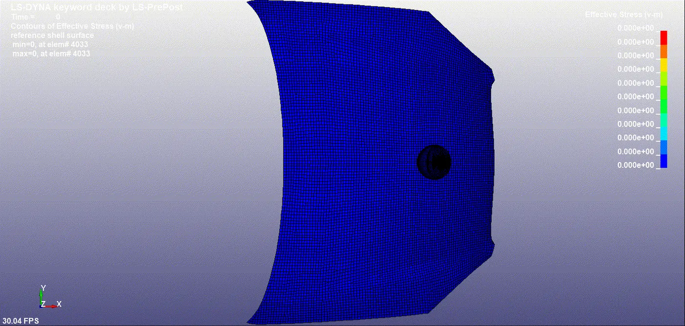
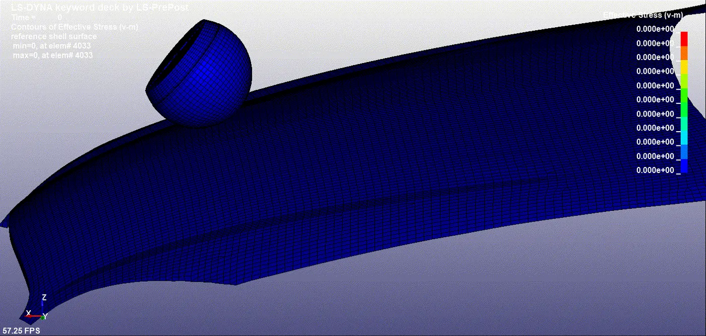
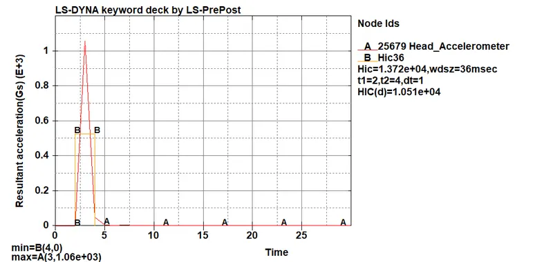
- The HIC36 value determined for this case is 1060 which comes under AIS 3 as mentioned earlier in case 2
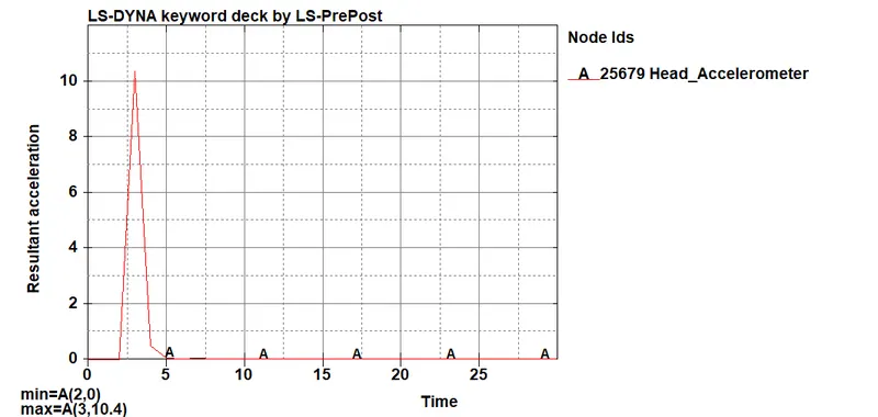
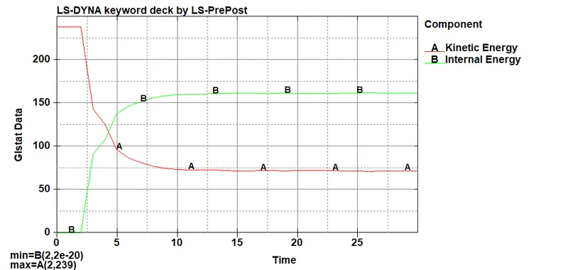
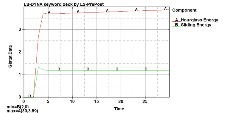
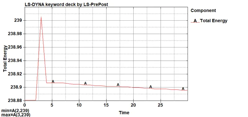
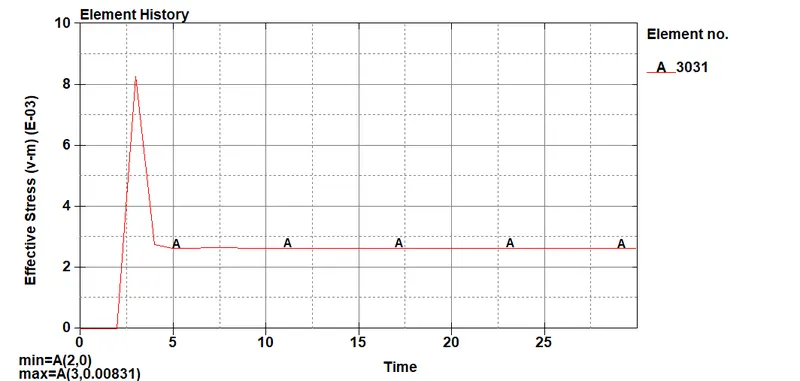
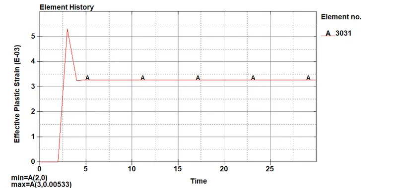
- The effective stresses (V-m) and plastic strain plots acquired from the simulations of head form with rigid wall and hood are quite different. The rigid wall possesses infinite stiffness as compared to the hood in which aluminum is used. Aluminium is less stiff and stronger than steel and thus induces lesser stress contrary to the rigid wall. Thus the plastic strains and effective stresses generated in the skin part of the head form are more in the rigid wall case.
CONCLUSION
- The HIC(Head injury Coefficient) computed in case 2 is a little bit more than in case 3. But both of them have the same AIB(Abbreviated injury scale) value i.e. Unconcious 1 to 6 hours; deepened fracture.
- The resultant acceleration established in case 2 is more than in case 3 as per final simulations.
- The stress and plastic strains accessed in case 2 are more than in case 3.
- As per the simulations, the permanent deformation is found in head form for case 2 whilst no such factor is observed in case 3.
- The various Glstat energies computed are quite equal for both cases. Although a significant amount of hourglass energy i.e. 3.89 is detected for both cases.