Week-6 Calculate the Stretch Ratio by comparing the ELFORM (-2,-1,1,2) with Ogden_Material Model.
Compare the ELFORM (-2,-1,1,2) with the Ogden_Material Model to get the Stretch Ratio
INTRODUCTION:
Matrix inversion (or analogous operations) is one way of solving for the unknowns x. This is referred to as an implicit analysis. The implicit analysis is used in this assignment for comparing various element formulations. When the issue is nonlinear, the solution is acquired in a series of stages, with the current step's answer relying on the previous step's solution. Inverting the matrix is quite costly for big models and will need complex iterative solvers (rather than conventional direct solvers). This is sometimes referred to as the reverse Euler integration scheme. These solutions are inherently stable and allow for bigger time increments. Despite this benefit, using implicit techniques to solve dynamic and nonlinear problems may be exceedingly time-consuming.
Material Type 77 is Mat_Ogden_Rubber. This material model includes the Ogden [1984] rubber model, as well as linear viscoelasticity as defined by Christensen [1980].
Element Formulations in LS-Dyna: Unless modified by THEORY in *CONTROL_SHELL, the default shell formulation is 2. THEORY is overridden by ELFORM in *SECTION_SHELL.
The following element formulations are used for implicit calculations:
2, 5, 6, 10, 12,12, 13, 14, 15, 16, -16, 17, 18, 20, 21, 22, 23, 24, 25, 26, 27, 29, 41, 42, 55.
AIM:
- Create a 10mmx10mmx10mm block with 10 components in each direction and use the material card attached (Ogden_Material.k) to reflect the material qualities seen in the picture above.
- Use suitable boundary conditions to replicate the model's tensile behavior, and then compare the results to the plot above up to stretch ratio 5. The only plot to be compared is the uniaxial plot.
- Compare the simulation results with ELFORM = 1, 2, -1, -2.
- In the material definition, the unit is in MPa and is a dimensionless quantity. Change the amounts to reflect your unit system.
- Use the appropriate solution (Implicit/Explicit) and explain why.
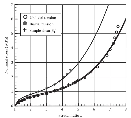
DELIVERABLES:
- An Excel file with accurate stress/strain and stretch ratio conversion and computation for every ELFORM.
- An accurate representation of the plot comparison of numerous ELFORMS versus the Uniaxial Plot provided in the challenge.
EXPLANATION:
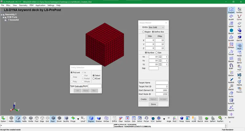
- In this assignment, we don't import the input keyword file rather we create one by using Mesh>Shape Mesher. A solid 10mm cube with 10x10 elements horizontally and vertically generated using this tool.
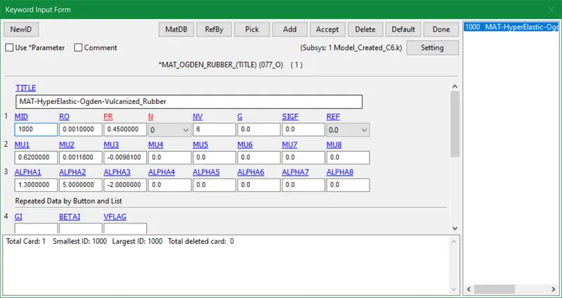
- The Material card is given in the assignment i.e Mat_Ogden_Vulcanized_Rubber. We copy the Mat keyword from a given input text file to our created keyword. Elsewhere we can create a new MAt_077 card from keywords and input given values.
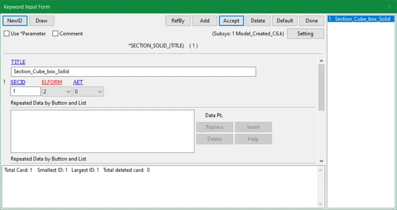
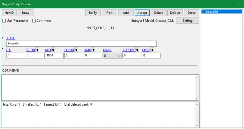
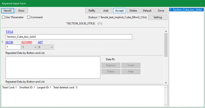
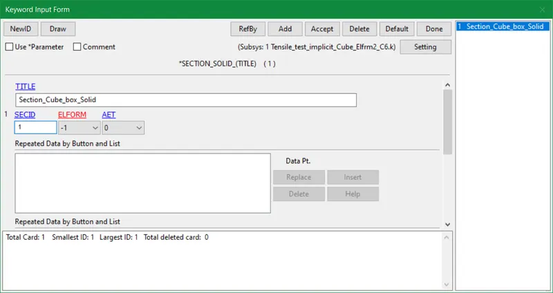
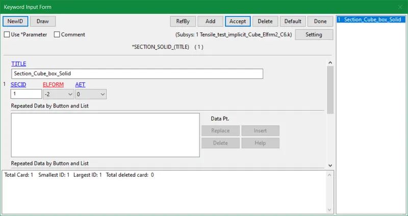
- Element Formulation 2 is analyzed first and later other forms provided in the assignment are assessed. So we facilitate the section_solid card with mentioned Elform.
- Case (1). ELFORM = 2, Fully integrated S/R solid
- Case (2). ELFORM = 1, Constant stress solid element.
- Case (3). ELFORM = -1, Fully integrated S/R solid intended for elements with poor aspect ratio, efficient formulation.
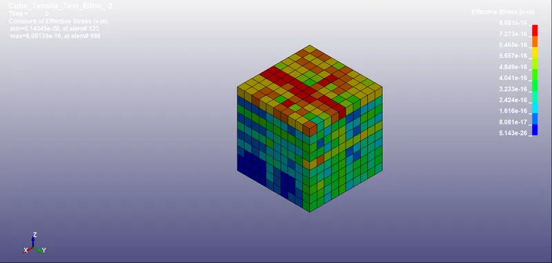
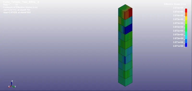
- Case (4). ELFORM = -2, Fully integrated S/R solid intended for elements with poor aspect ratio, accurate formulation.
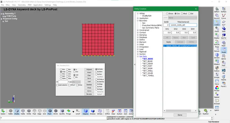
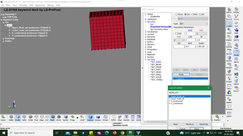
- Now it is time to give displacement to the cube for the tensile test using implicit analysis. Henceforth we will create upper nodes and lower nodes as displayed below using Create Entity tool.
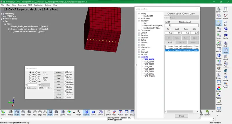
- The displacement for the solid cube is specified along Z-axis. Hence we create two more sets of nodes along the X and Y axis in order to constrain the elements.
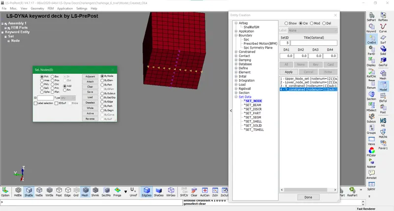
- It is time to input boundary conditions by establishing SPC on the lower node-set. It constrains the chosen direction or axis of the node set.
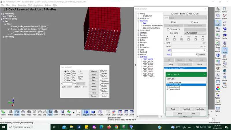
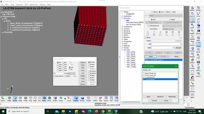
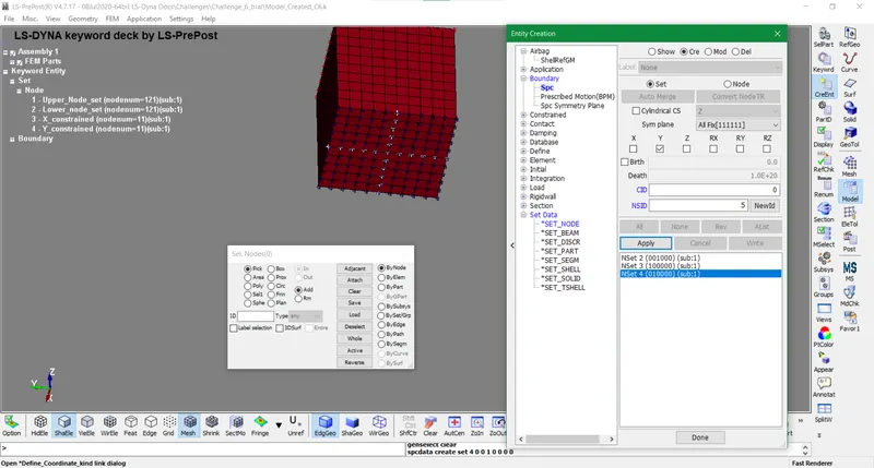
- Afterward, we need to give motion or displacement to the upper node set towards the z-axis. But before that, we define a displacement vs time curve to run the simulation effectively with proper results.
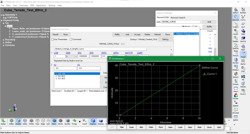
- So we create a boundary-prescribed motion using create entity tool and assign an upper node set with the curve established above. Since we are using displacement as a motion factor and not initial velocity so we keep the VAD value as 2.
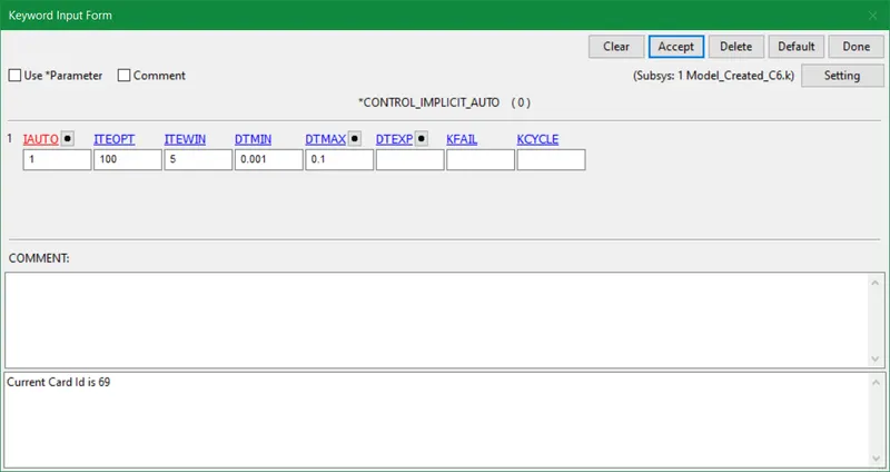
- To facilitate implicit analysis for this model we create Control_Implicit, Control_Implicit_General and Control_Implicit_solution cards. We adjust the minimum allowable time step size (DTMIN) and maximum allowable time step size(DTMAX) w.r.t the loading conditions.
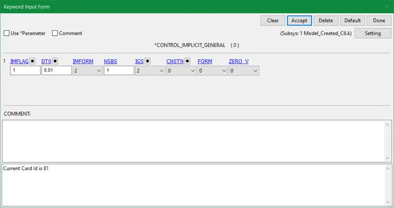
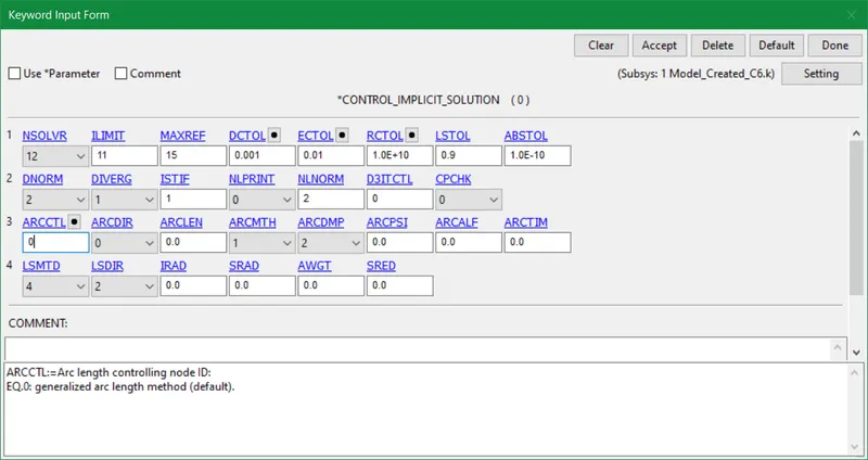
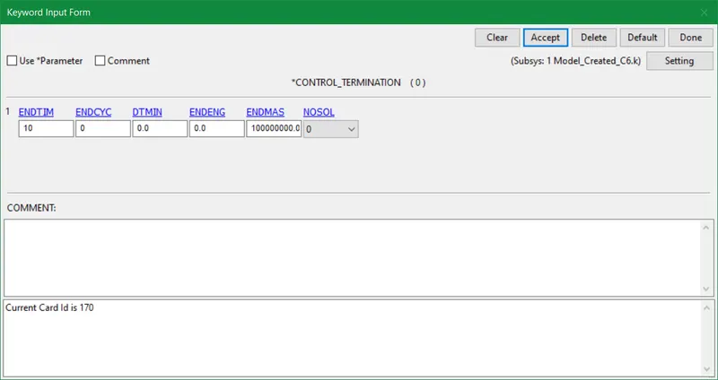
- The termination time or analysis time is inputted creating the control_termination card as per requirement.
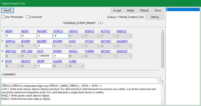
- In the database keyword, we create extent_binary which controls the content of binary output databases d3plot, d3thdt, and d3part to some extent. The STRFLG is regulated to 1 which is a flag for output of strain tensors.
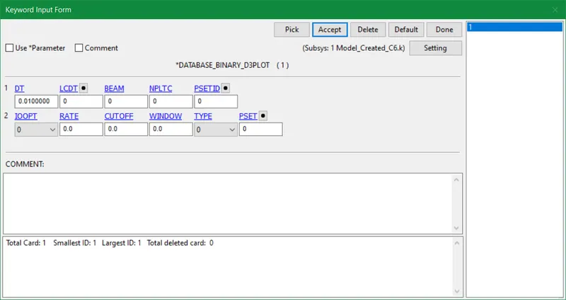
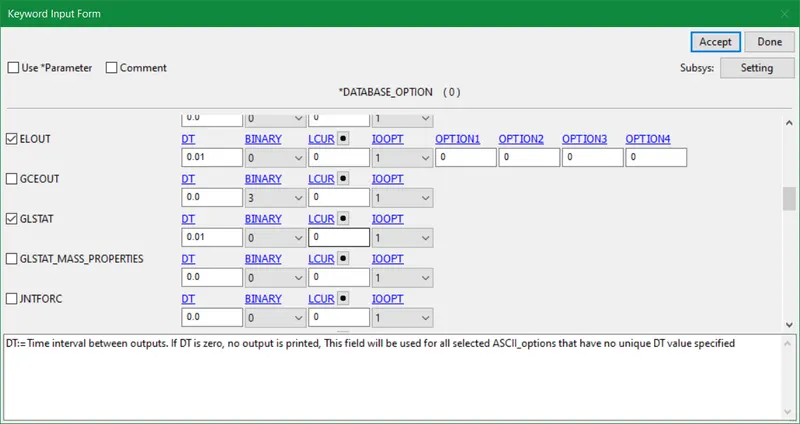
- In database_ASCII we input 4 items that are required for computing data.
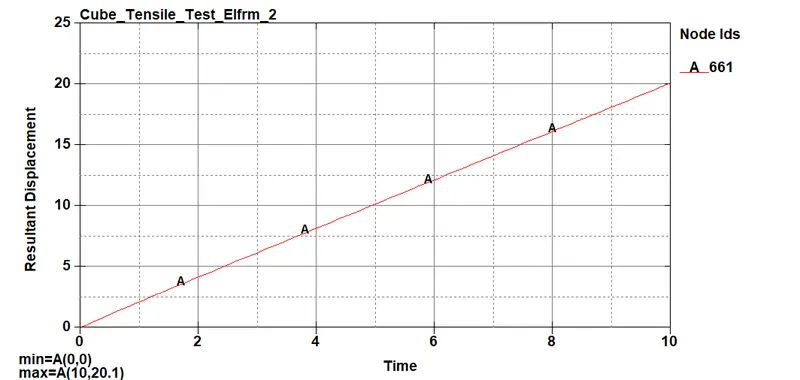
- The middle node and solid element in the cube are designated in the history_node and history_solid card. It is used to compare displacement and effective stress between all element formulations used in this assignment.
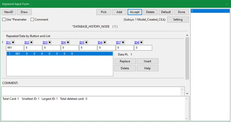
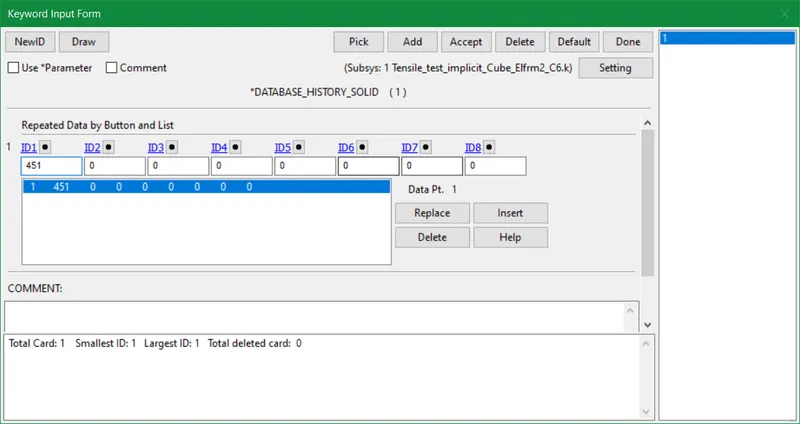
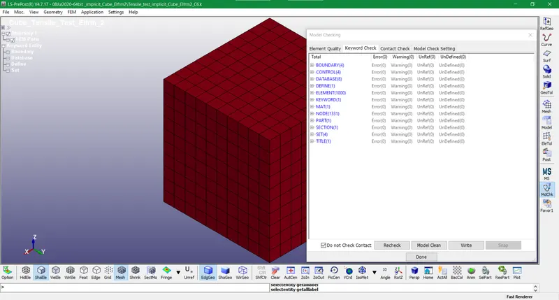
- Lastly, the model checking is done, and since no errors are found we initiate running the simulation.
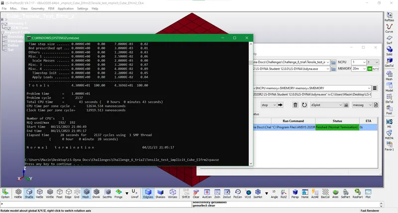
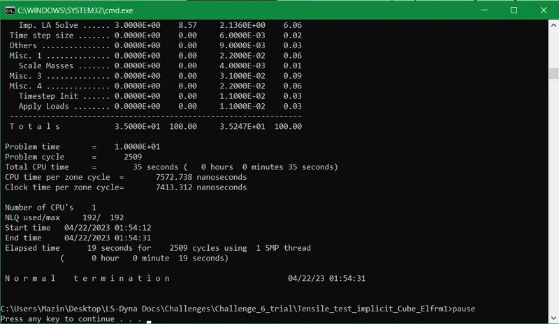
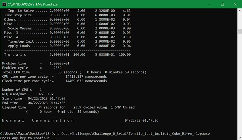
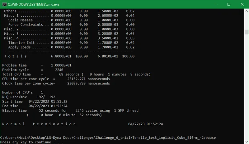
- The normal termination report is evaluated with 28 seconds of elapsed time. For the rest of the element formulations we only modify the elform in the section card and run the simulation. We evaluate the results of each elform and compare them in order to attain the best accurate and precise output.
ELEMENT FORMULATION 2
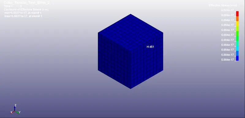
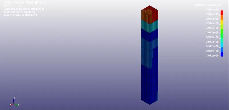
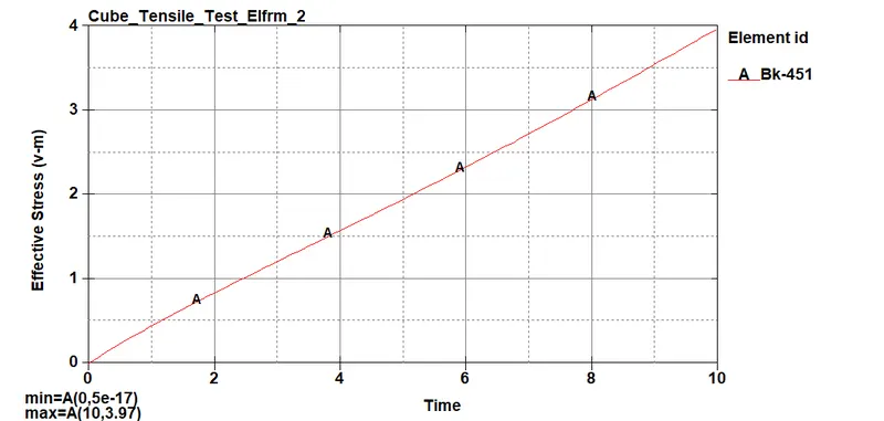
- The simulation of effective stress (Von-mises) for elform 2 is displayed below
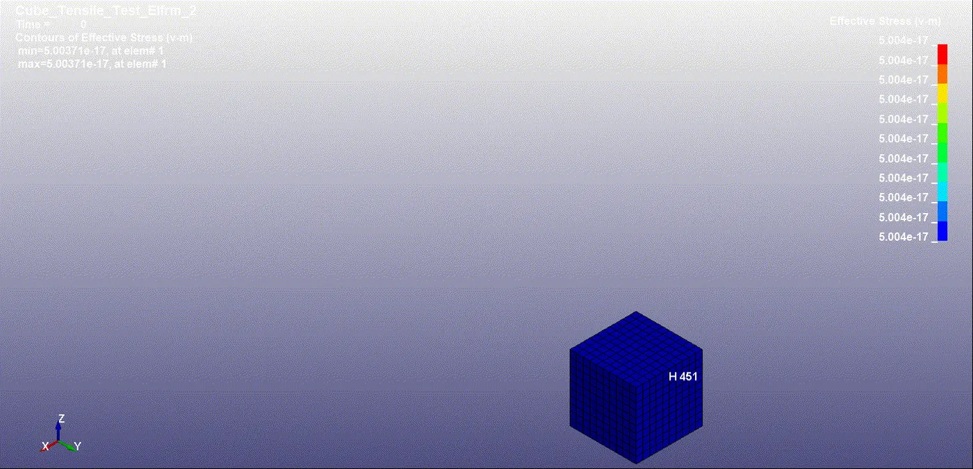
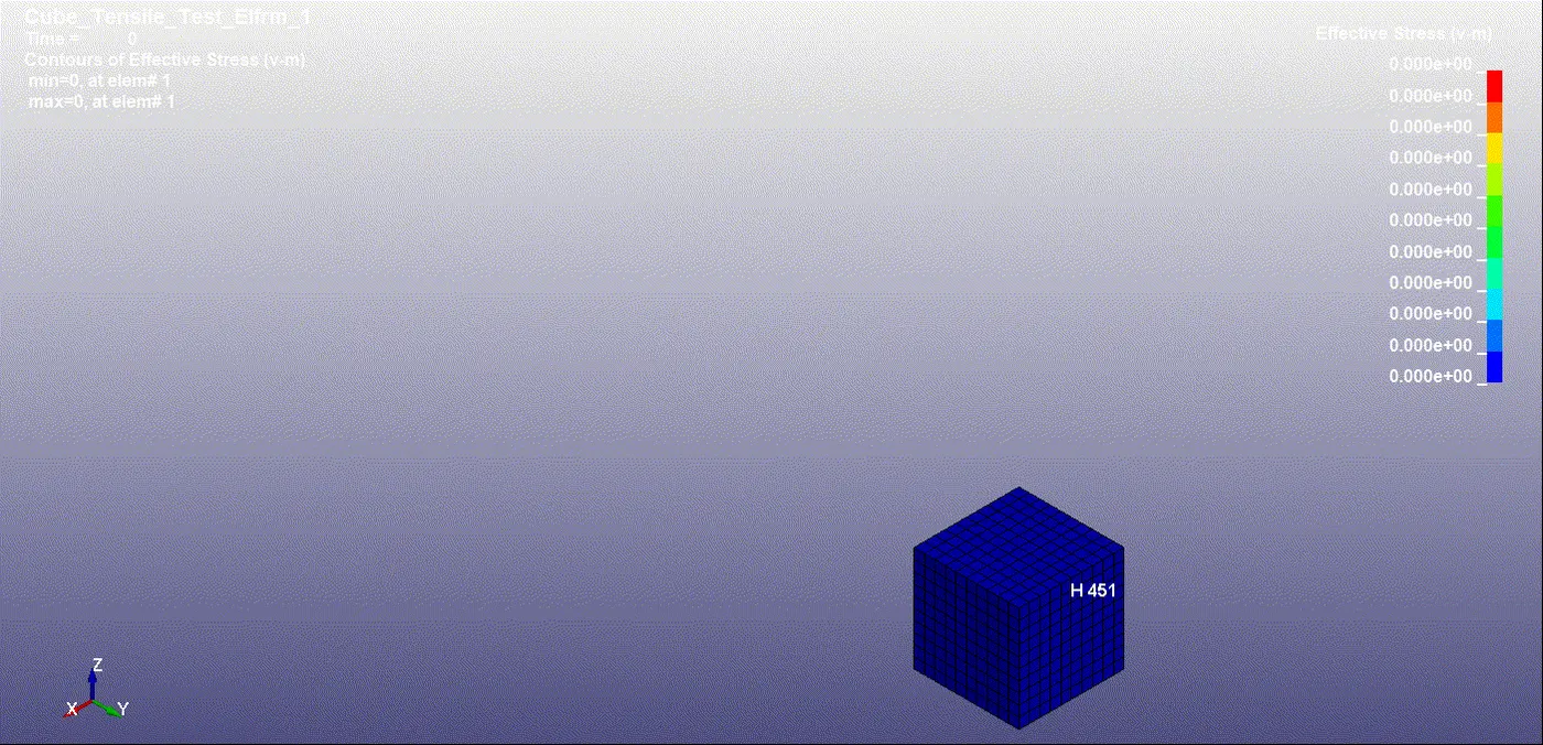
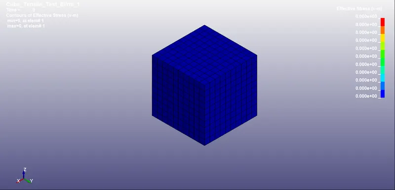
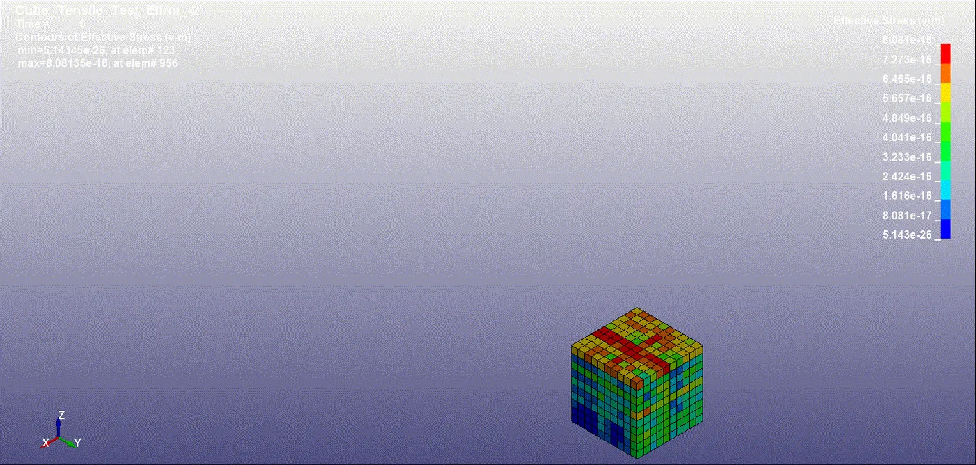
- The initial changes of the cube in elform2 for effective stress at the beginning of the analysis is portrayed as follows
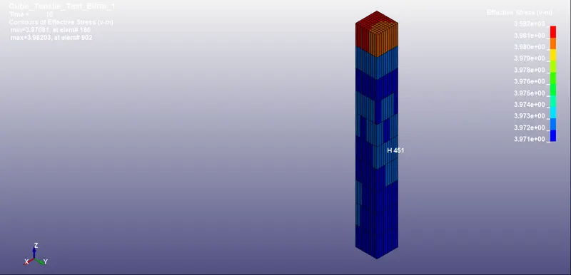
- The final changes of the cube in elform2 for effective stress at the end of the analysis are portrayed as follows
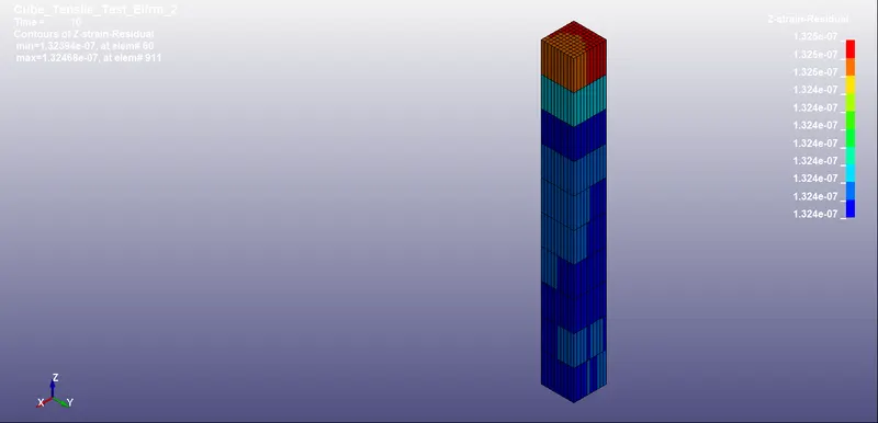
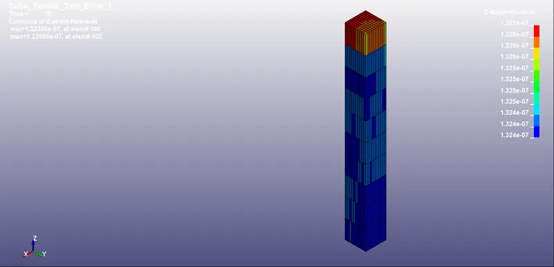
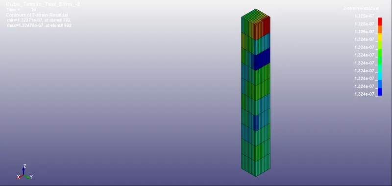
- The effective strain(v-m) is similar to effective stress so we monitored the z-strain for the given elform.
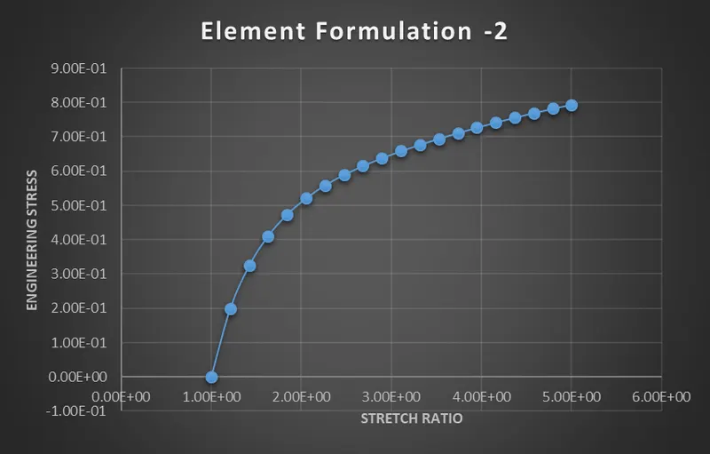
- In this model, we use control units such as grams, millimeters, and milliseconds for quantitative analysis. The numerical data used to obtain the Engineering stress vs stretch ratio graph is described as follows:
Engineering strain is defined as,
e = dl/l
Where, dl = change in length and l = original length
The stretch ratio, l = 1 + e
As given l = 5
So e = 4
Also, l = 10mm as per the given dimensions of the cube
Hence dl = 40
-
Exp(e*) – 1 = e where, e* = True strain
s = s* / Exp(e*) where, s* = True stress and s = Engineering stress
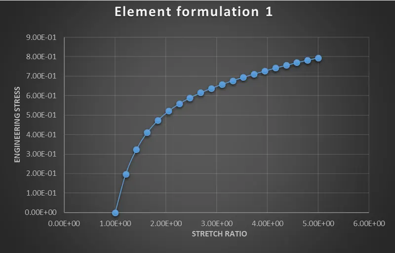
The values for engineering stress and strain are tabulated by choosing the same element in the middle of the cube for all Elforms. We plot the results for z-stress and lower ipt z-strain and quantify them as true stress and strain. Using the above formula we derive the engineering stress and strain and compare the graphs between all elforms.
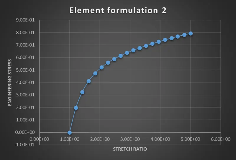
- The effective stress and resultant displacement are found same for all 4 elforms used in this model.
ELEMENT FORMULATION 1
ELEMENT FORMULATION -1
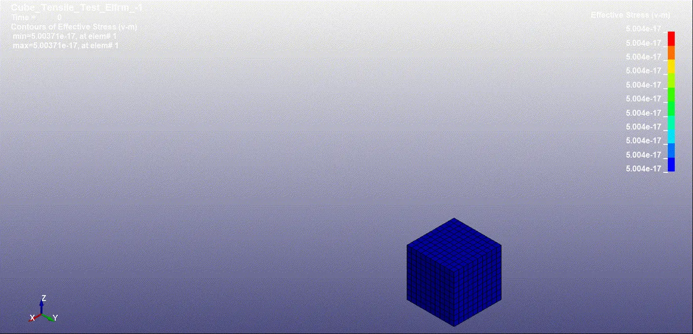
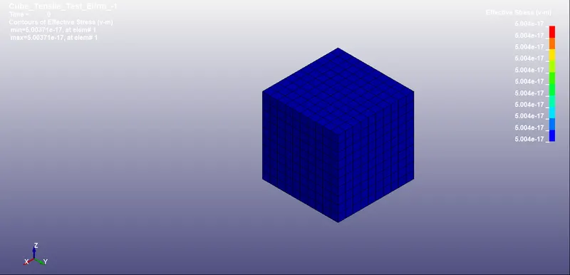
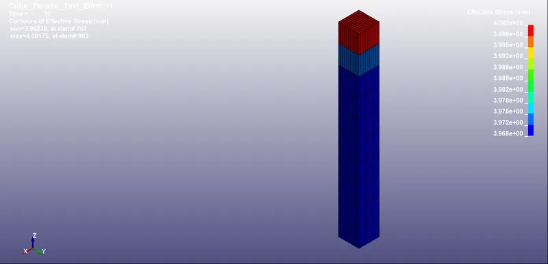
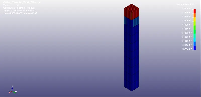
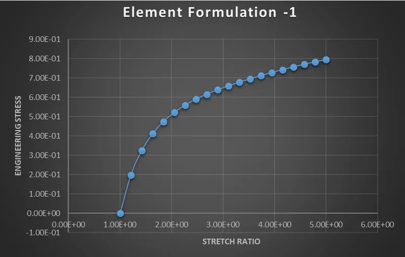
ELEMENT FORMULATION -2
CONCLUSION:
- There is a negligible difference in engineering stress vs stretch ratio plots among all 4 elforms used in this model.
- The elapsed time is found lesser in Elform1 as compared to others which are high for the same model.
- In elfrm -2 the stresses are induced more at the beginning of the simulation as compared to others. Thus it shows that it can resist strain in solid elements more than others.
- There is not much difference but the strain found in elfrm 1 is low contrary to others and thus demonstrates sheer low plasticity.