Week 1 Stress Concentration on a Plate with hole
STRESS CONCENTRATION ON A PLATE WITH HOLE
INTRODUCTION
Stress concentration is the localization of excessive stress brought on by component abnormalities and sudden cross-sectional shifts.
Stress concentration factor: This factor is used to determine the localized stress and take into account the effects of stress concentration.
The source of stress concentrations: Machine members frequently have locations where the level of stress is noticeably higher than theoretical projections as a result of
- Geometric discontinuities or stress rises, such as holes, notches, and fillets;
- Tiny internal imperfections (non-homogeneities) in the material caused by manufacturing techniques like molding and casting.
- Surface imperfections brought about by machining procedures, such as cracks and markings.
Decrease in Stress:
- More notches and holes in the tension member;
- A filler radius, undercutting, and notch for the member in bending;
- Drilling more holes for the shaft;
- A notch and undercut are supplied in the threaded member.
Theories of failures:
Maximum principal stress theory: According to this theory, the machine member will fail when the maximum principal stress obtained through bi-axial, stress system at a strained particle of that member reaches the limiting strength of the member when it is subjected to a simple tension test. Generally the limiting strength for ductile material is yield stress and for brittle material is the ultimate tensile stress.
Maximum shear stress theory: According to this theory, the machine member will fail when the maximum
shear stress due to bi-axial stress system reaches the shear yielding stress in simple tension test.
Von misses hanky or Distortion energy theory: According to this theory failure of mechanical component
subjected to biaxial or triaxial forces occurs when the strain energy distortion per unit volume at any point of
component becomes equals to the strain energy of the standard specimen. This theory applicable for both
ductile and brittle material.
OBJECTIVES
CASE 1:
Design a plate with a hole model similar to what we worked in the class, but with increased thickness.
Determine the maximum deformation and stress developed in the model.
Plate dimensions:
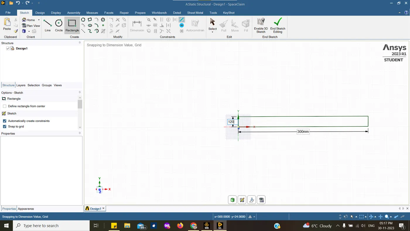
Length=300mm
Height=120mm
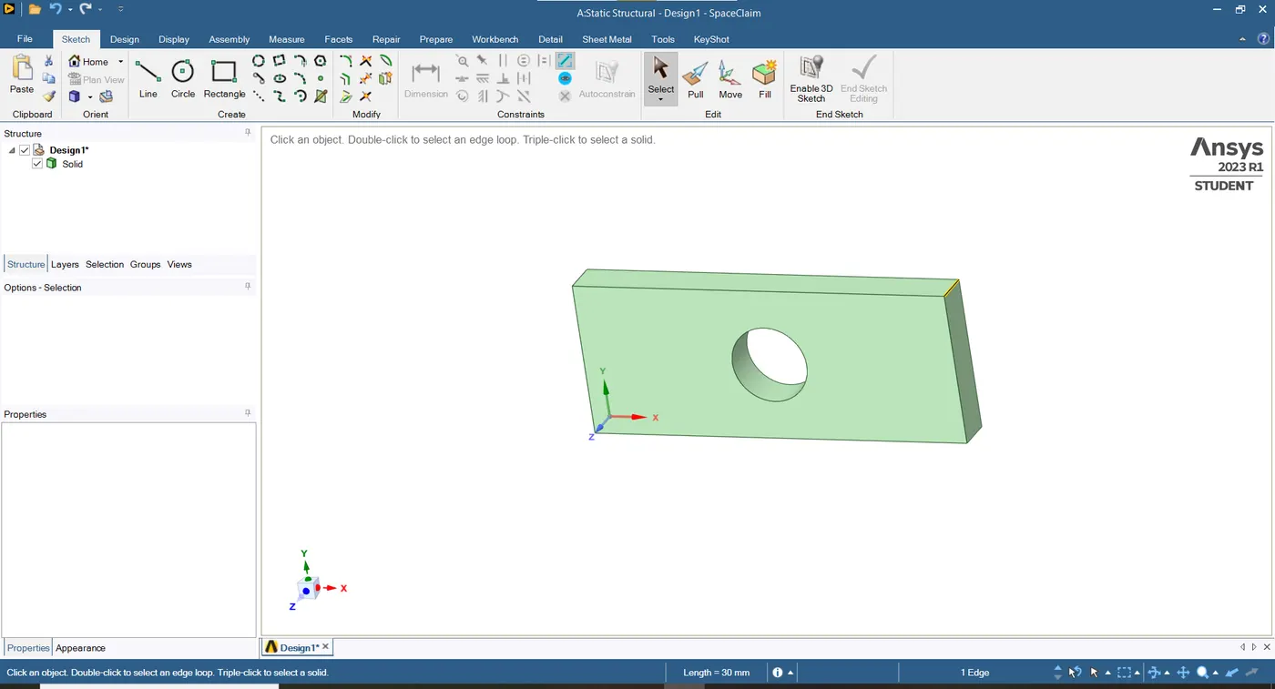
Thickness=30mm
Circular Hole at the center:
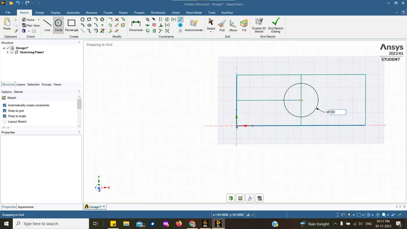
Diameter=60mm
CASE 2:
-
Compare the deformation and maximum stress developed on a structural steel model for the 2 cases
-
From an analysis standpoint, which of the design will you select? Explain why?
-
From a manufacturing standpoint, which of the design will you select? Explain why?
PROCEDURE
CASE 1:
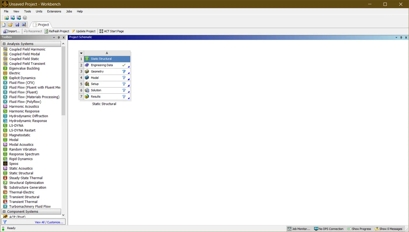
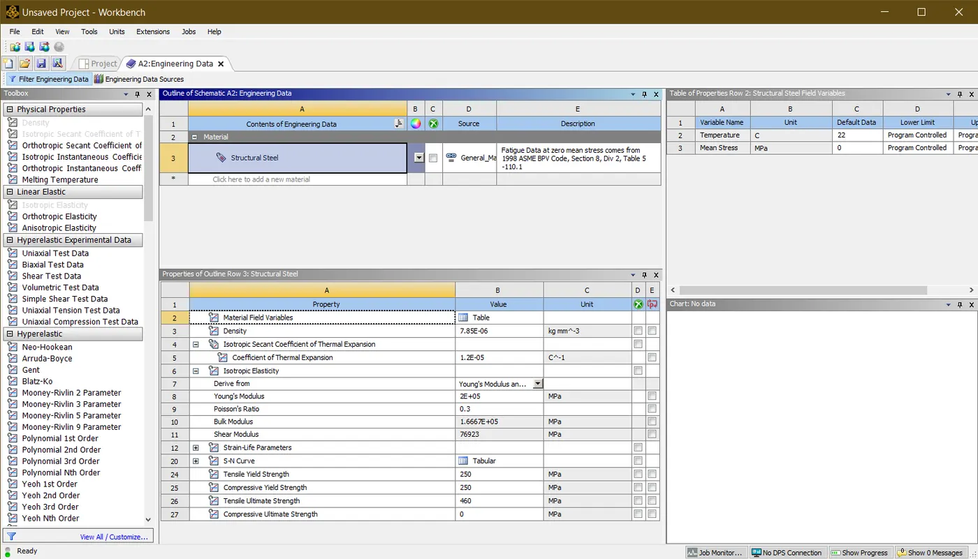
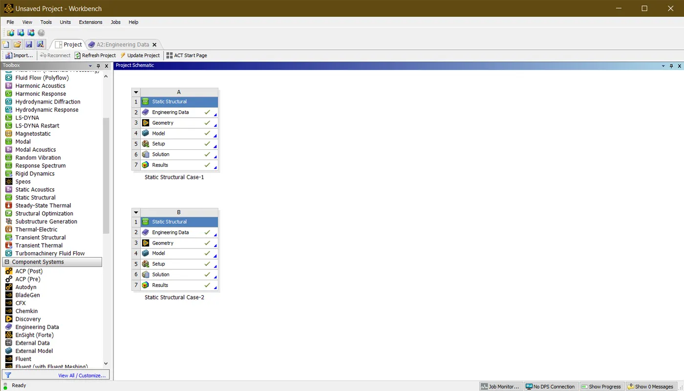
- The task commences with establishing a novel static structural system within ANSYS Workbench. For engineering data, the structural steel with designated units is allocated and modified.
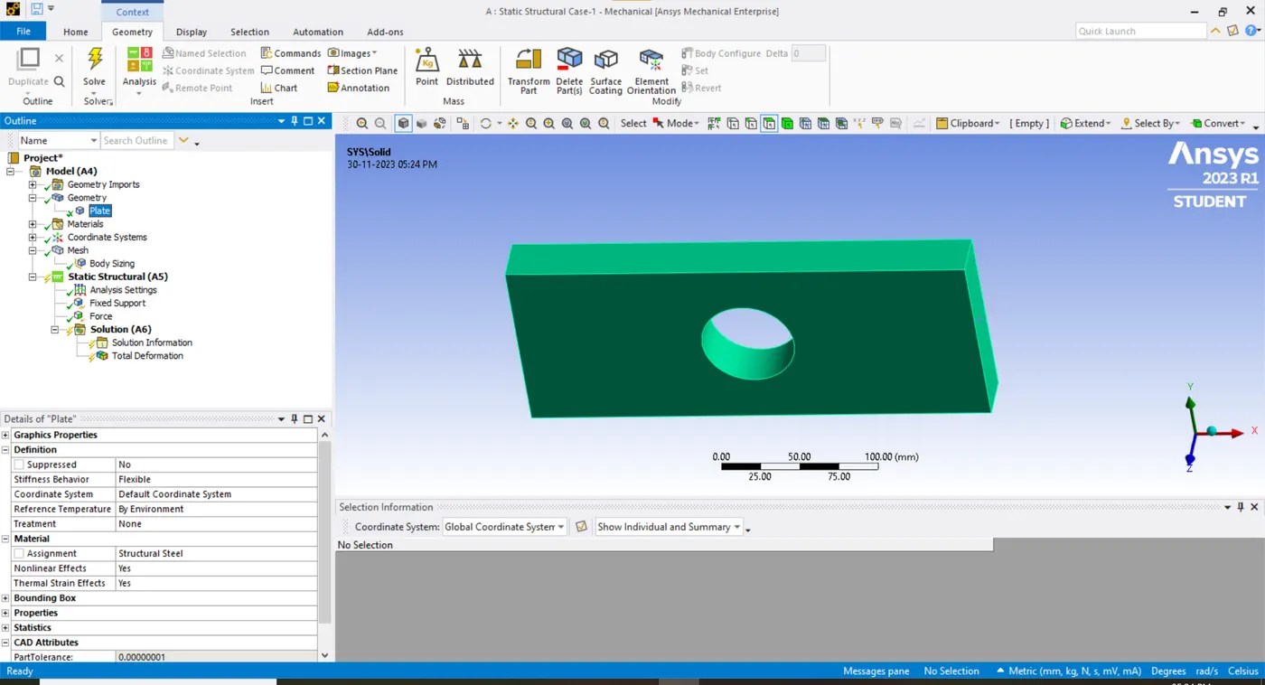
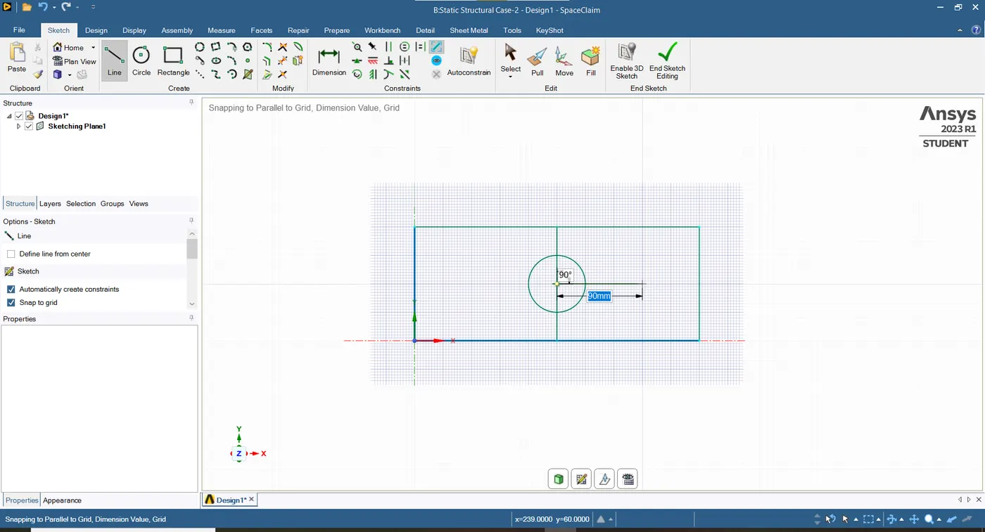
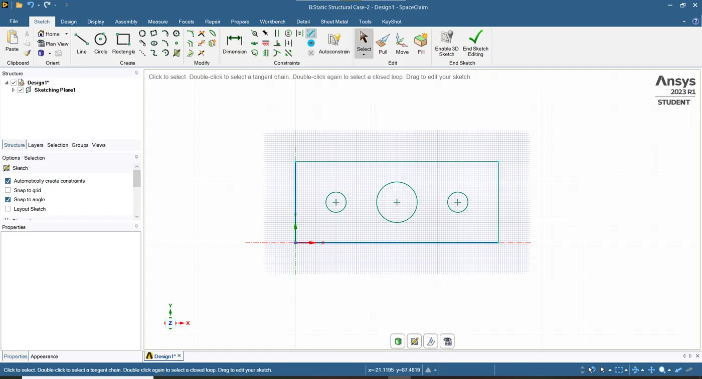
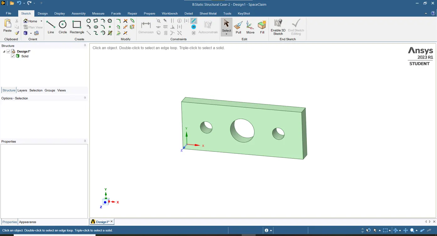
- The geometry is created or imported using Space Claim in the geometry item of the static structural system. The dimensions of a plate with a central hole are developed using specific space claim tools as displayed below.
- Once the material assignment and geometry are modelled we move to the pre-processing phase using ANSYS Mechanical.
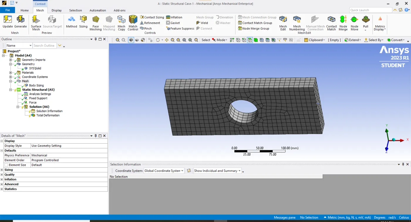
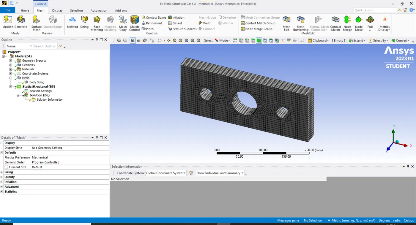
- The meshing with the appropriate mesh method and size is done on the model.
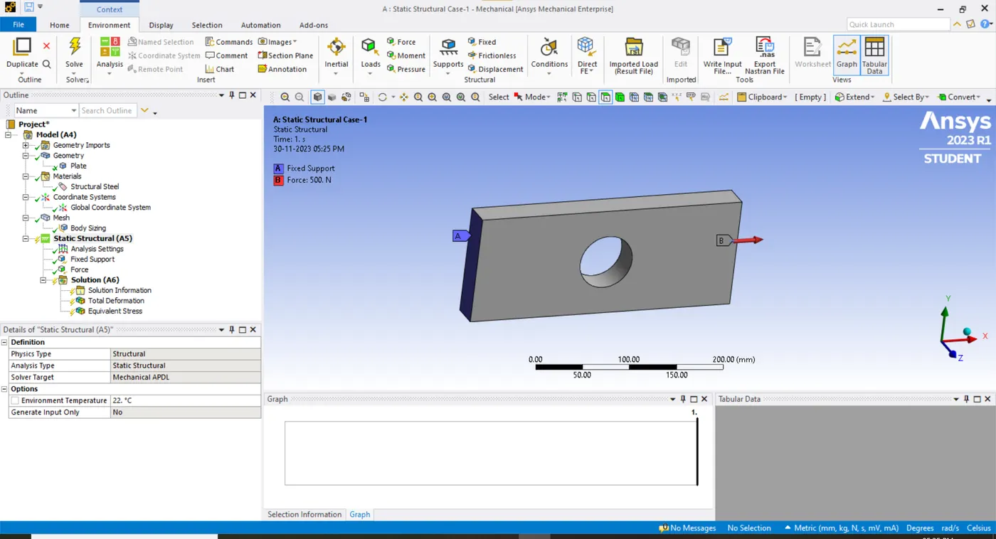
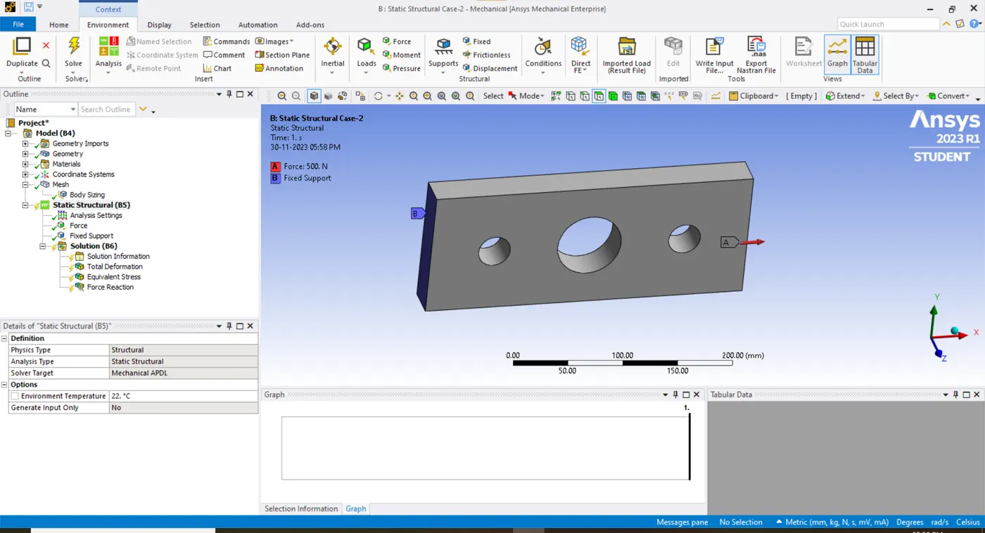
- As prescribed the boundary conditions and loading conditions are described on the plate. The load is provided on one end to establish a tensile test on the model.
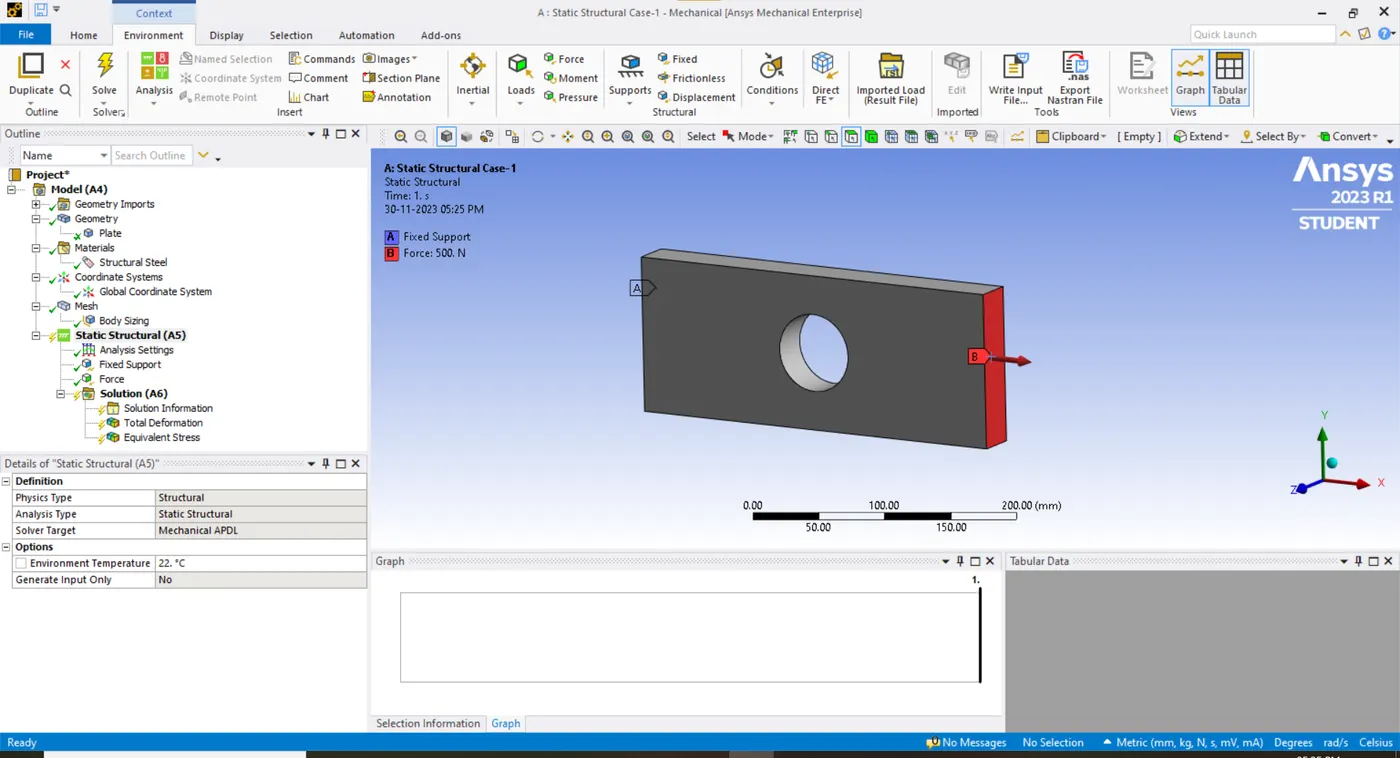
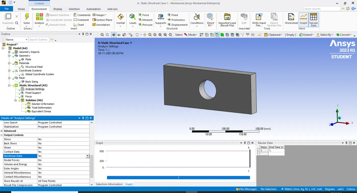
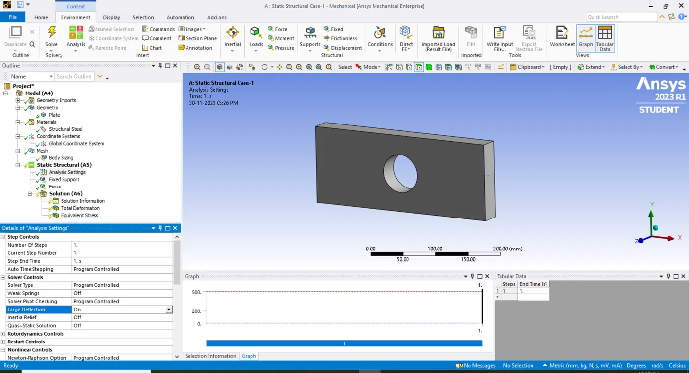
- The time step, load step, large deformation, output controls, and so on are adjusted as per the type of design, material, conditions, requirement and analysis.
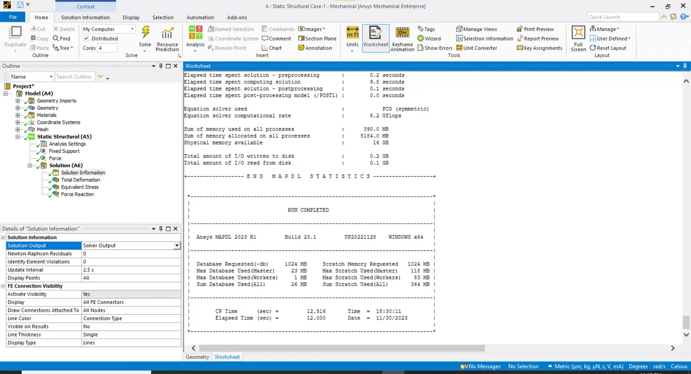
- The solving is done after completing all pre-processing stages and the solution information is thoroughly examined.
CASE 2:
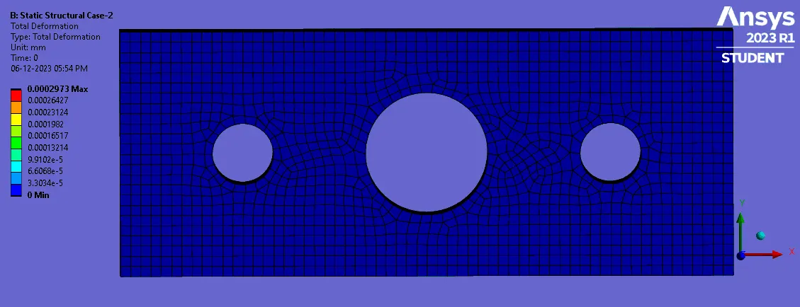
- In Case 2, a new Static structural system is established, and the geometry is created with given dimensions and the same materials assigned to it. Rest all the stages are approached in a similar manner as Case 1.
RESULTS
The post-processing results formulated after attaining the solution are described below:
CASE 1:
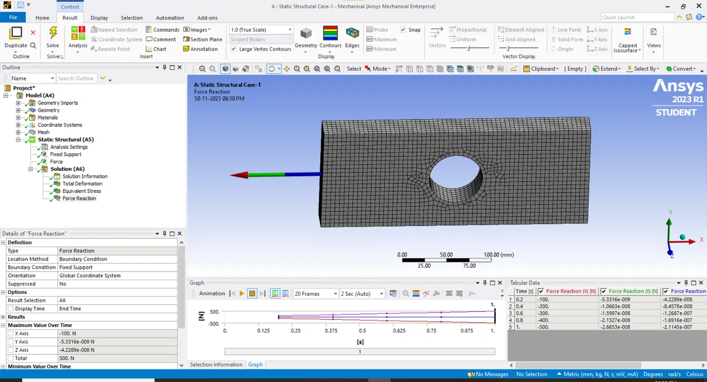
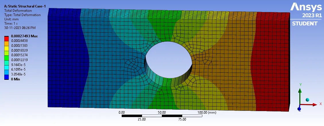
- The Force reaction of the load applied on one end of the plate is found to be equal as shown below with negligible losses.
CASE 2:
CONCLUSION
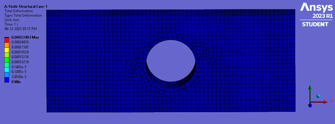
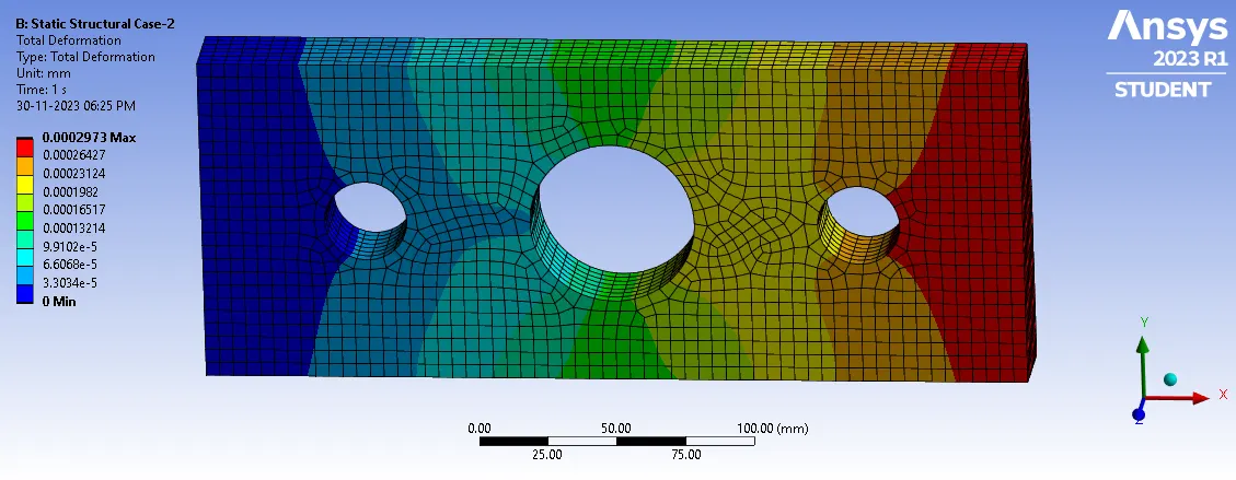
- The deformation attained is low at the fixed end and high at the end where the load is applied outwards in both cases.
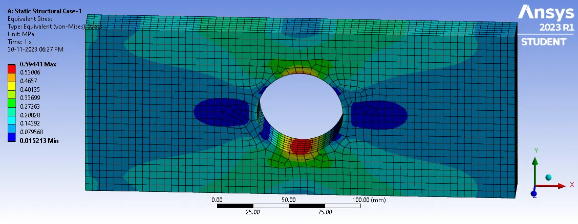
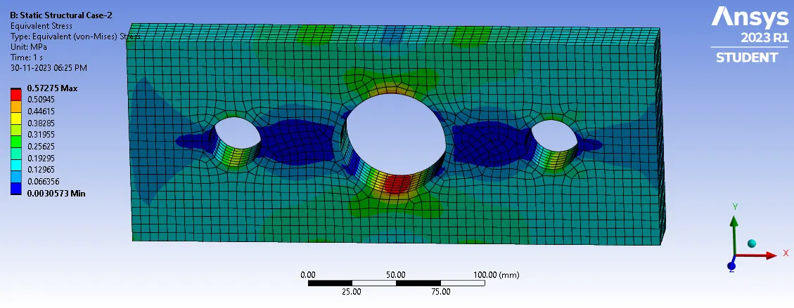
- The Equivalent stress in both cases is examined to be highest at the periphery of the holes. This leads to the concept of stress concentration which is observed at the holes in tension members usually.
- The deformation and stress are both lesser in Case 2 as compared to Case 1.
- From an analysis standpoint, the design from Case 2 is preferred. The stress concentration evaluated from Case-2 is lesser in comparison to Case-1 due to more holes. So for efficient and optimized results, Case 2 is prioritized.
- From a manufacturing standpoint, the design from Case 1 is preferred. The construction of extra holes in Case 2 is a time-consuming process with additional accessories attached to it. Henceforth in terms of Cost-effectiveness, it is not up to the mark.