Assignment 1-2D Meshing Challenge
2D MESHING USING HYPERMESH
INTRODUCTION
Model parts that are essentially two-dimensional, like sheet metal or a hollow plastic cowl or casing, are represented by a surface mesh, sometimes known as a "shell mesh".
When building more intricate 3D meshes, surface meshes placed on the exterior faces of solid objects serve as a baseline mapping point. A 3D mesh's quality is primarily determined by the 2D mesh it is derived from.
One computer-aided engineering (CAE) program used for finite element analysis (FEA) is called HyperMesh. It is a finite element modelling preprocessor that enables users to produce CAD geometry's finest surface meshes.
Part of the Altair HyperWorks CAE software suite, HyperMesh is created by Altair Engineering. It is a potent simulation tool that transforms CAE design procedures in a variety of sectors.
Leading multi-disciplinary finite element pre-processor HyperMesh controls the creation of the biggest, most intricate models on the market. It enables users to handle and arrange particular collections of items, such as surfaces, curves, elements, or nodes.
The priorities of analysts attempting to use the data differ from those of designers when they build CAD geometry. Usually, a single smooth surface is divided into smaller patches, each of which is a distinct mathematical face. There are frequently gaps, overlaps, or other misalignments at the junction of two surfaces.
To improve the geometry's suitability for meshing, analysts must merge several faces into a single, smooth surface. This eliminates the need for extraneous artificial or inadvertent edges to appear in the final mesh and enables the creation of the elements on the entire region at once.
You can prepare surface geometry for meshing with the tools in the Quick Edit, Edge Edit, Point Edit, and Autocleanup panels.
OBJECTIVES
Carry out the geometry cleanup operation on the given 3 files.
-
Practice
-
Clip Repair
-
Mounting Bracket
There should not be any free edges, convert all of them into refined geometry.
-
Clean the geometry.
-
Extract midsurface.
-
Clean midsurface geometry.
-
Ignore holes less than dia 5mm.
-
Create 2D mesh with target length 5mm, min 3.5mm max 7mm.
-
And assign proper thickness, by creating a generic property.
-
Then Save in .hm format.
PROCEDURE
MODEL-1
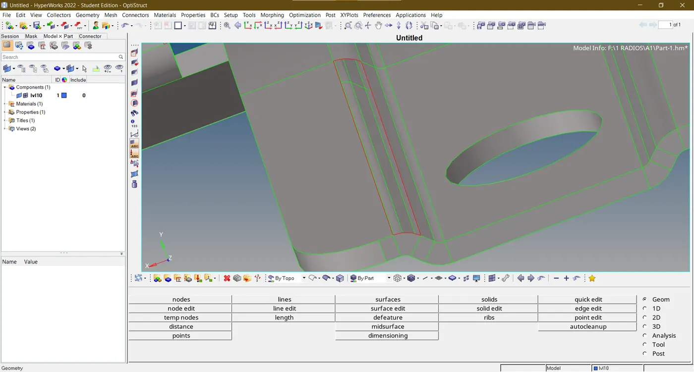
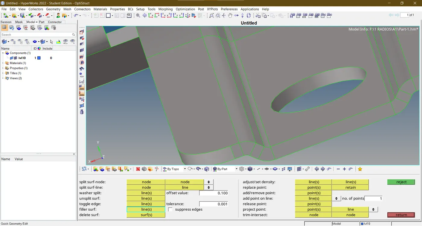
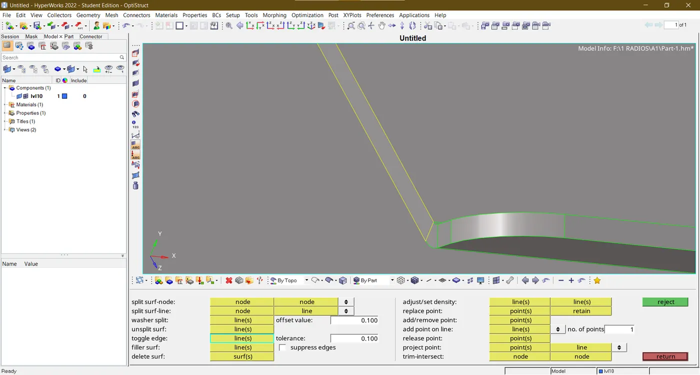
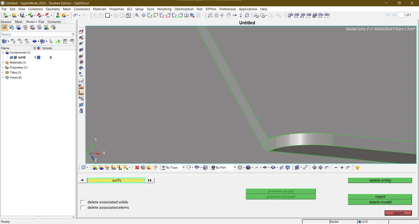
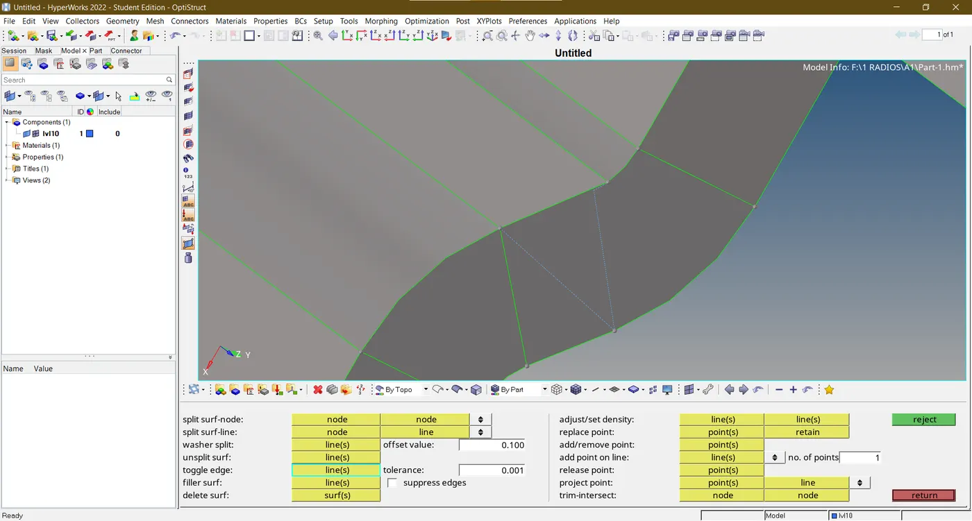
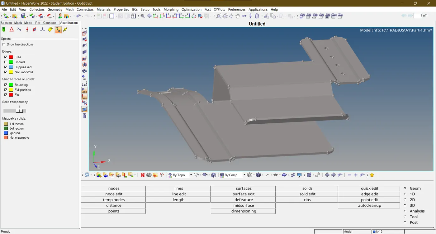
- The model is imported using the open model/import geometry option in the Toolbar. The geometry is thoroughly examined and a lot of errors are spotted. So using a specific set of tools as portrayed in the pictures below the geometric clean-up process is executed.
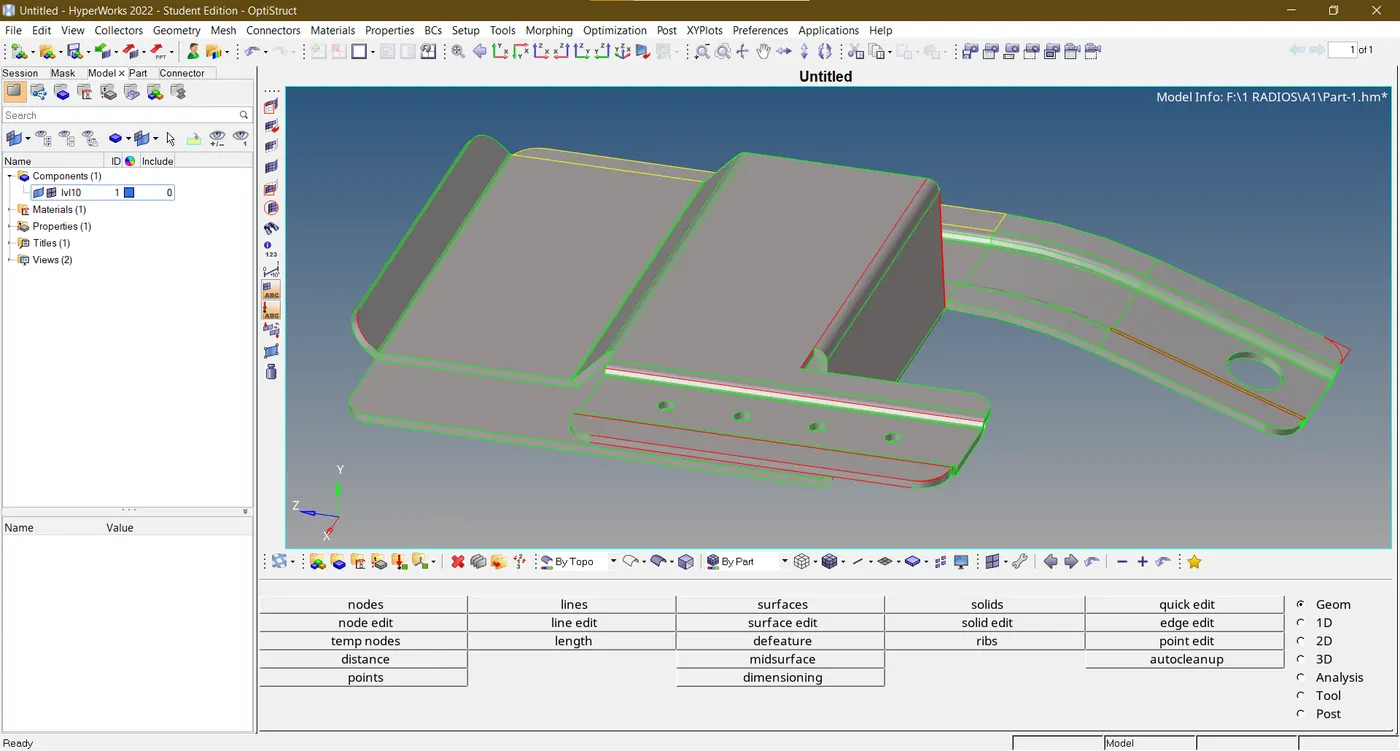
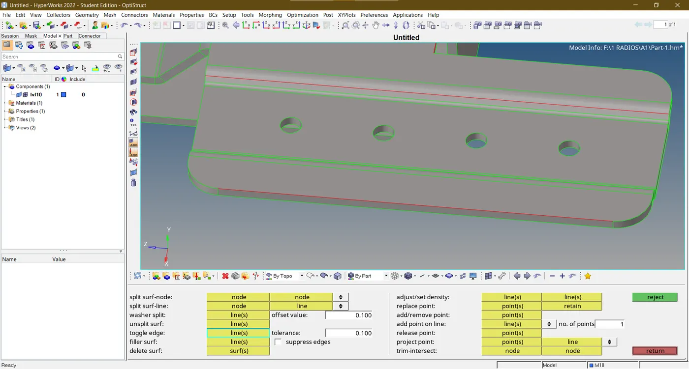
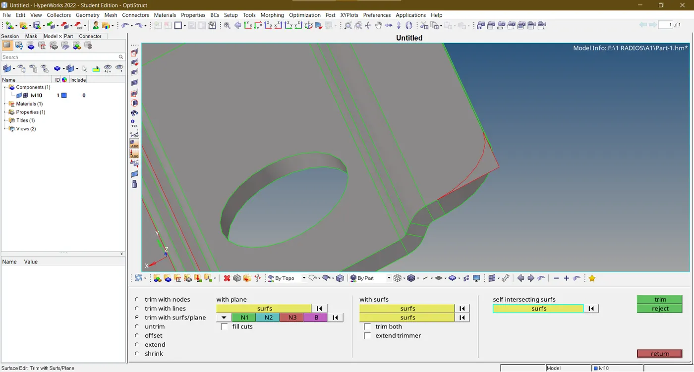
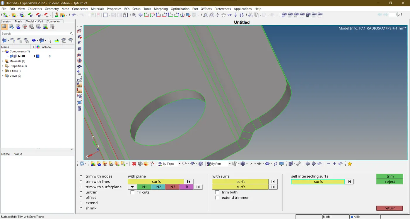
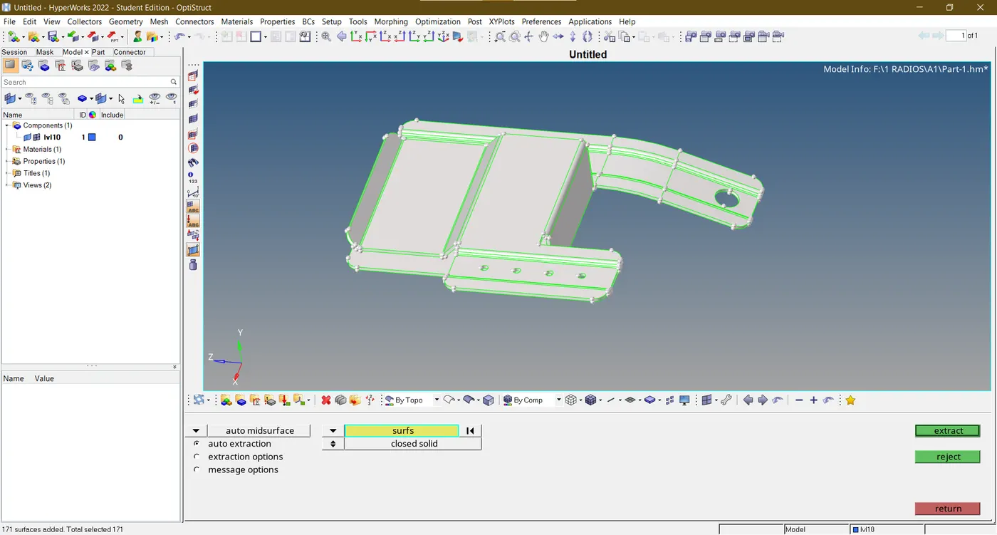
- After clearing all geometrical errors the mid-surface is extracted for the component using the Auto-mid surface option in the Geom panels bar. It is a sheet metal component because the thickness measured is uniform throughout.
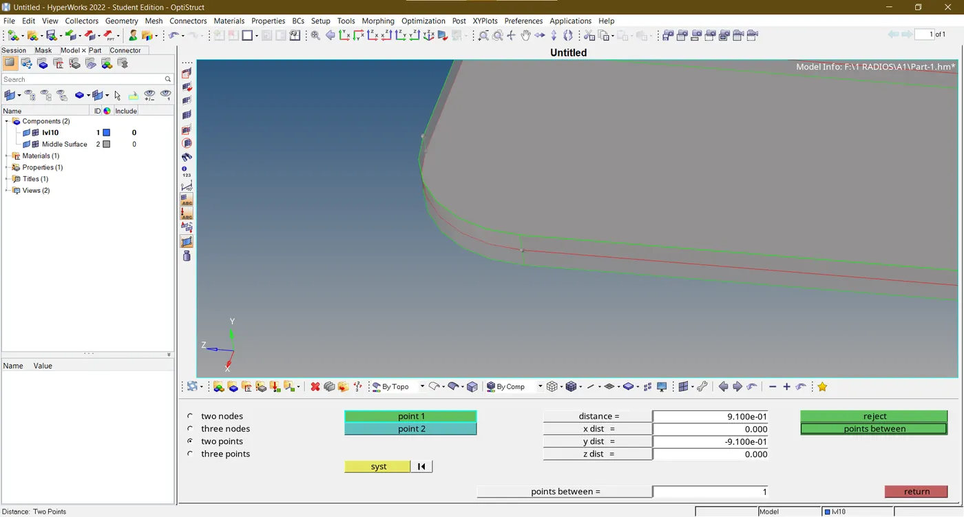
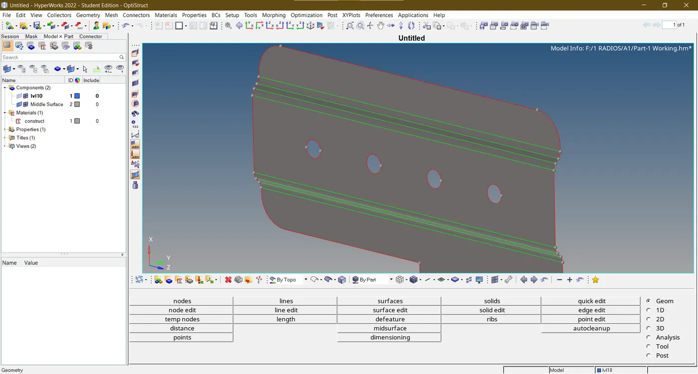
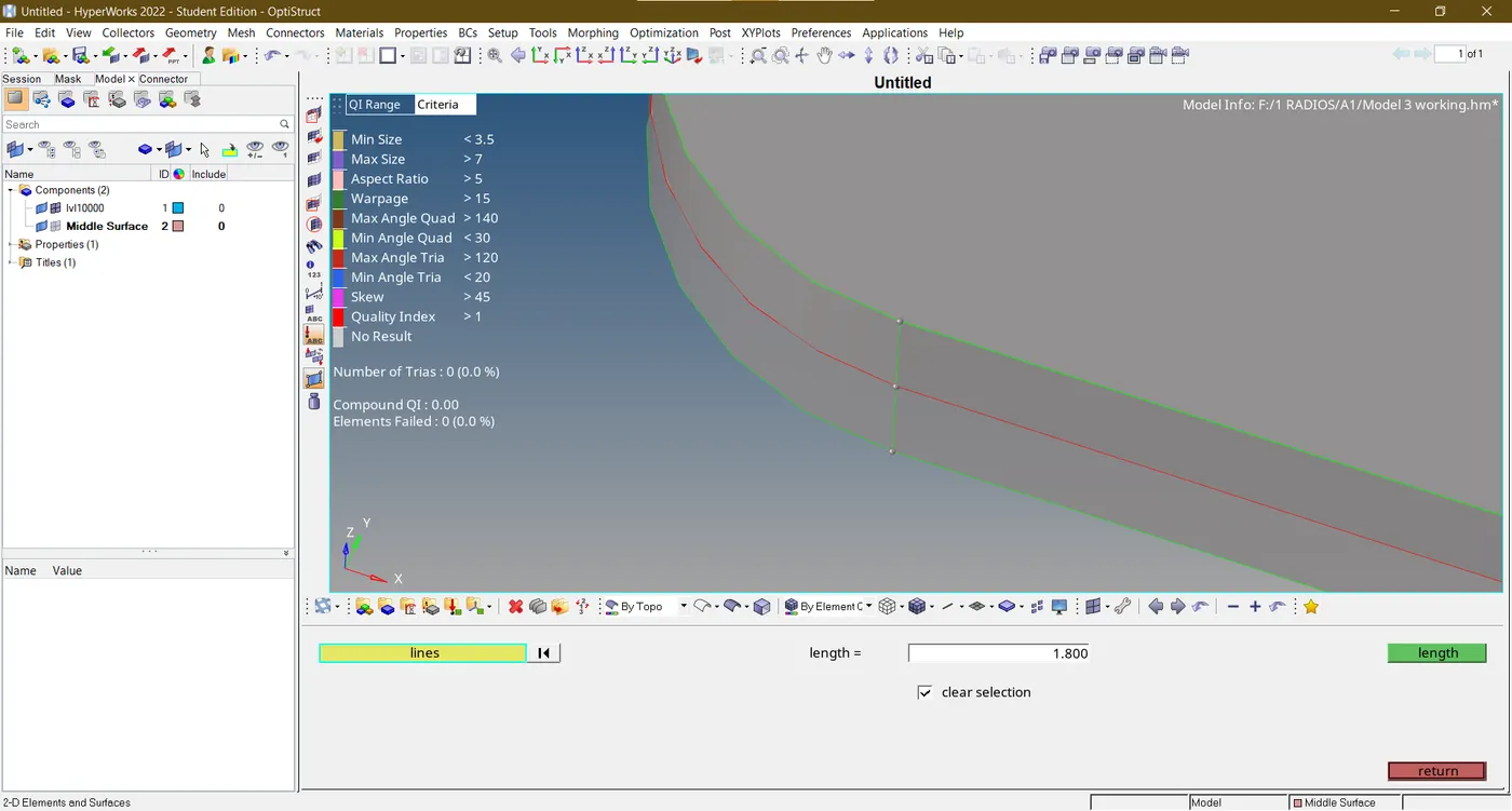
- The fillets and some areas are failing for minimum element length quality criteria as per prescribed criteria settings. The unnecessary edges are defeatured and mid-lines are created as displayed below.
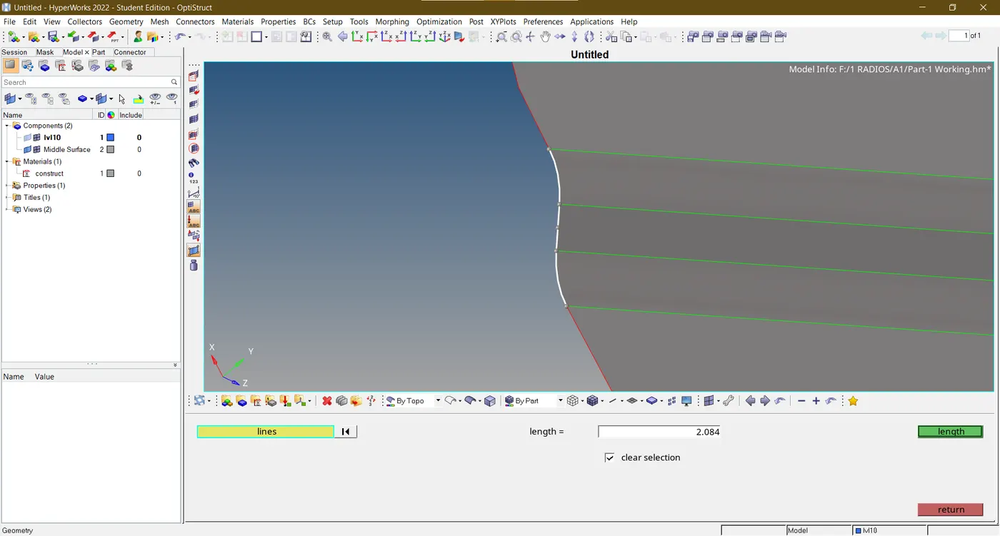
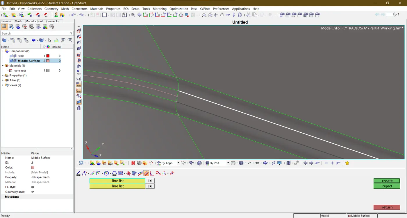
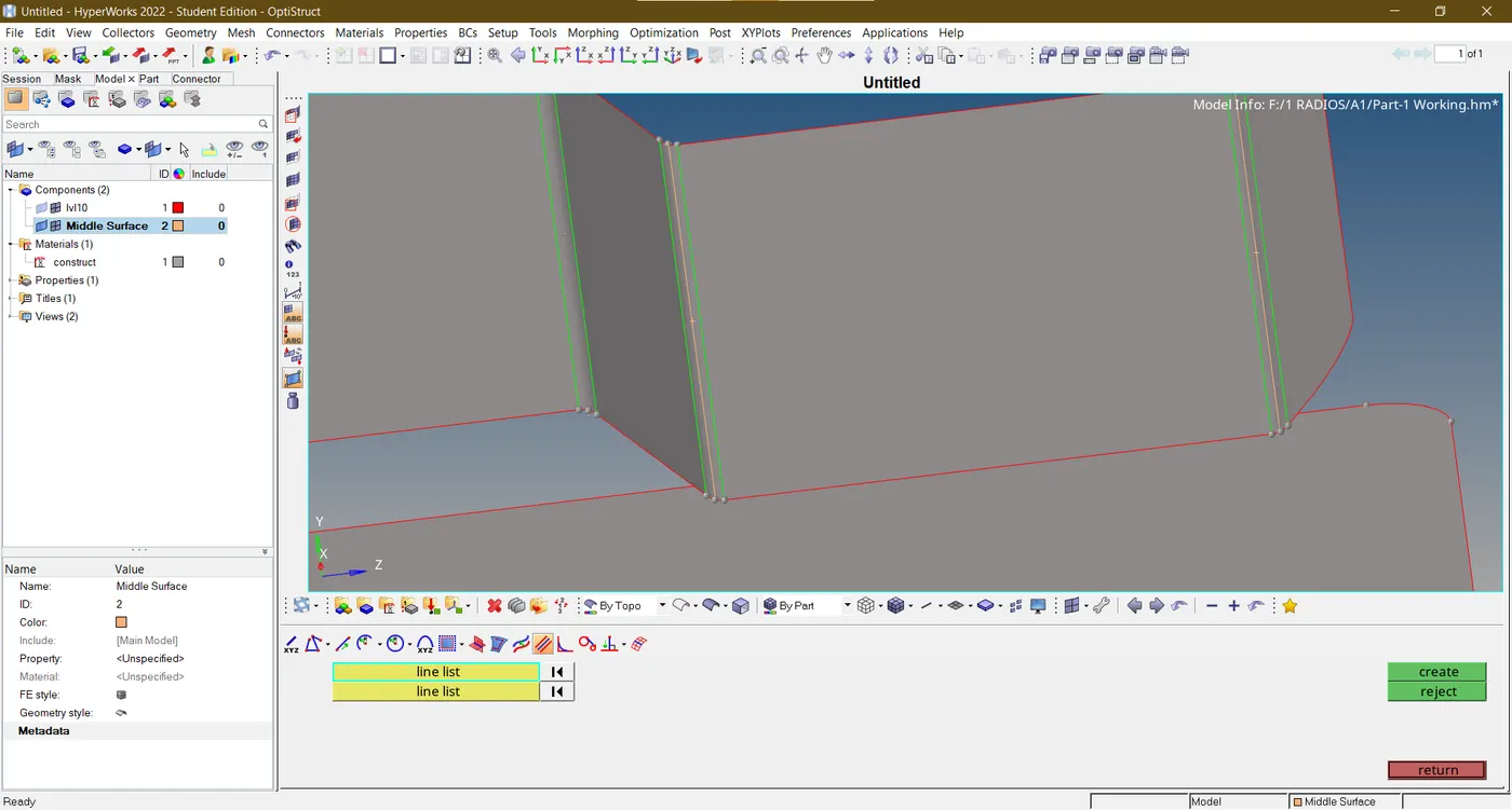
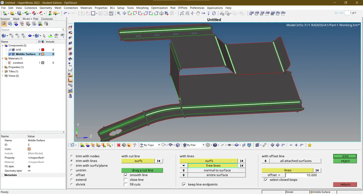
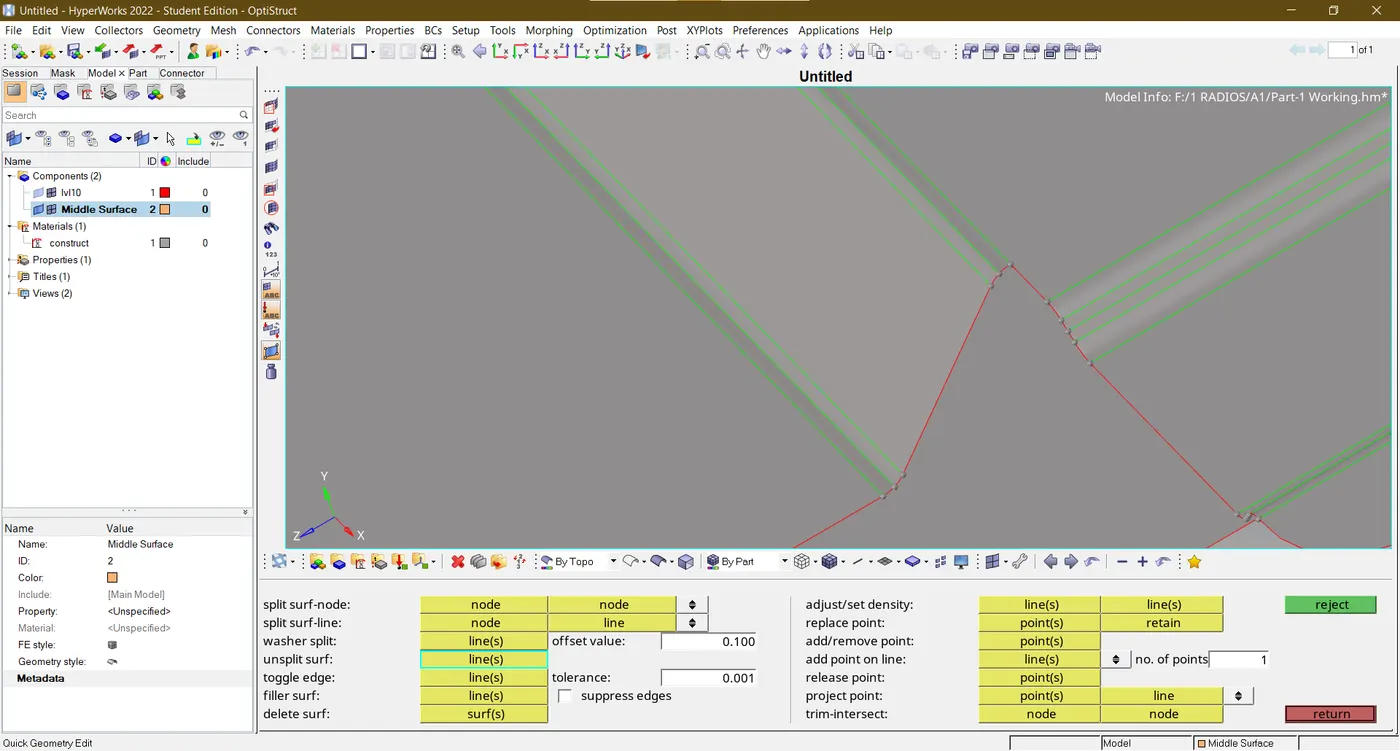
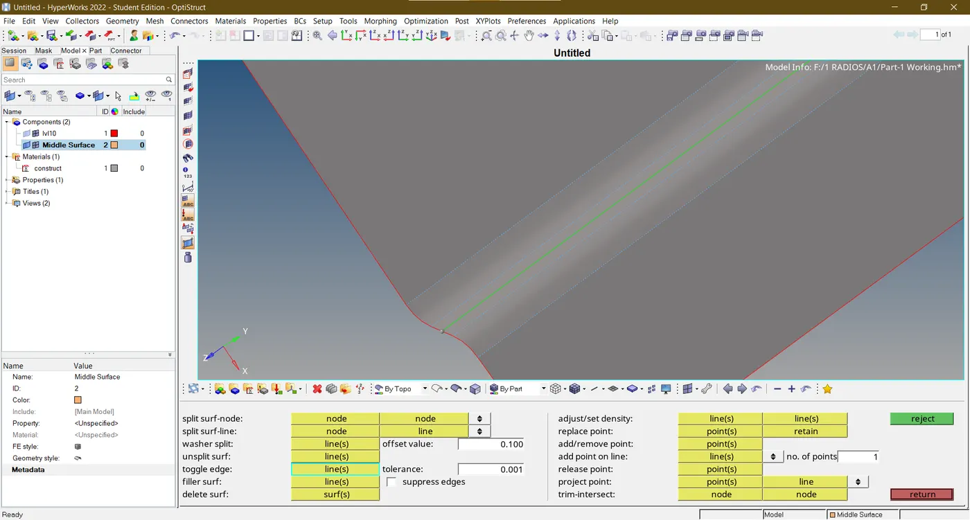
- Hence after defeaturing the given quality criteria is inputted in criteria settings before meshing.
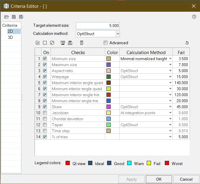
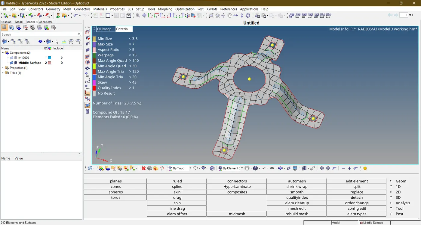
- The meshing process is proceeded by using a set of tools to clear quality errors and trias on all surfaces of the component.
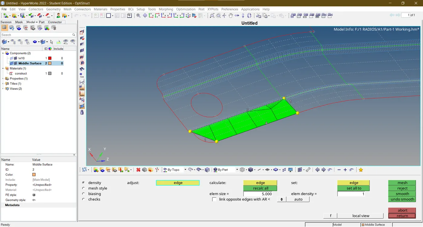
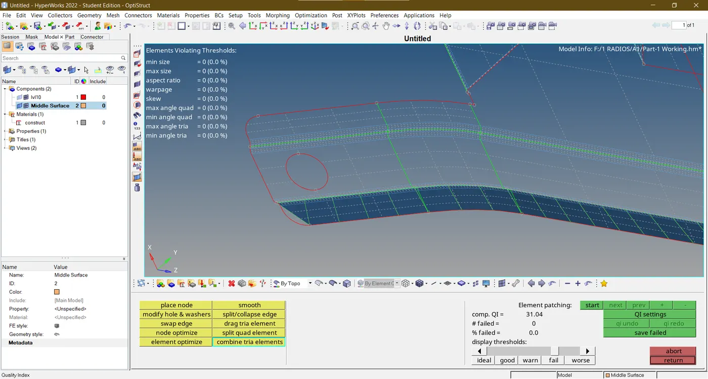
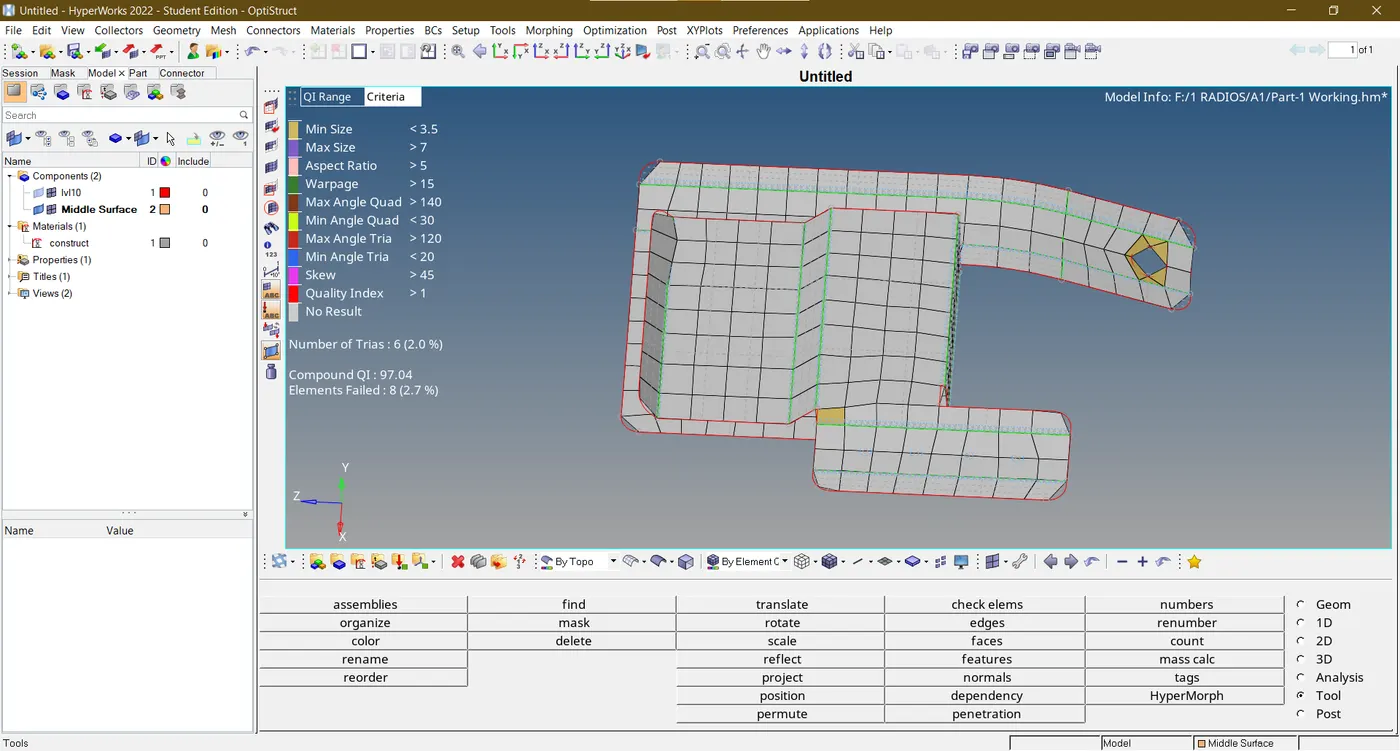
- Lastly, create a property and assign the desired thickness measured from the original geometry on the mid-surface.
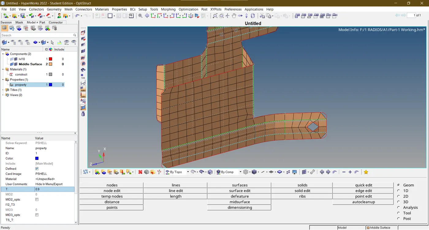
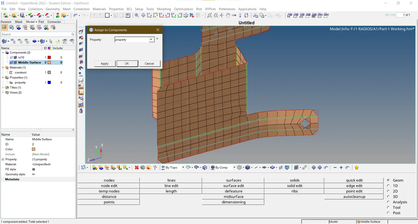
- The final image of the model is displayed below.
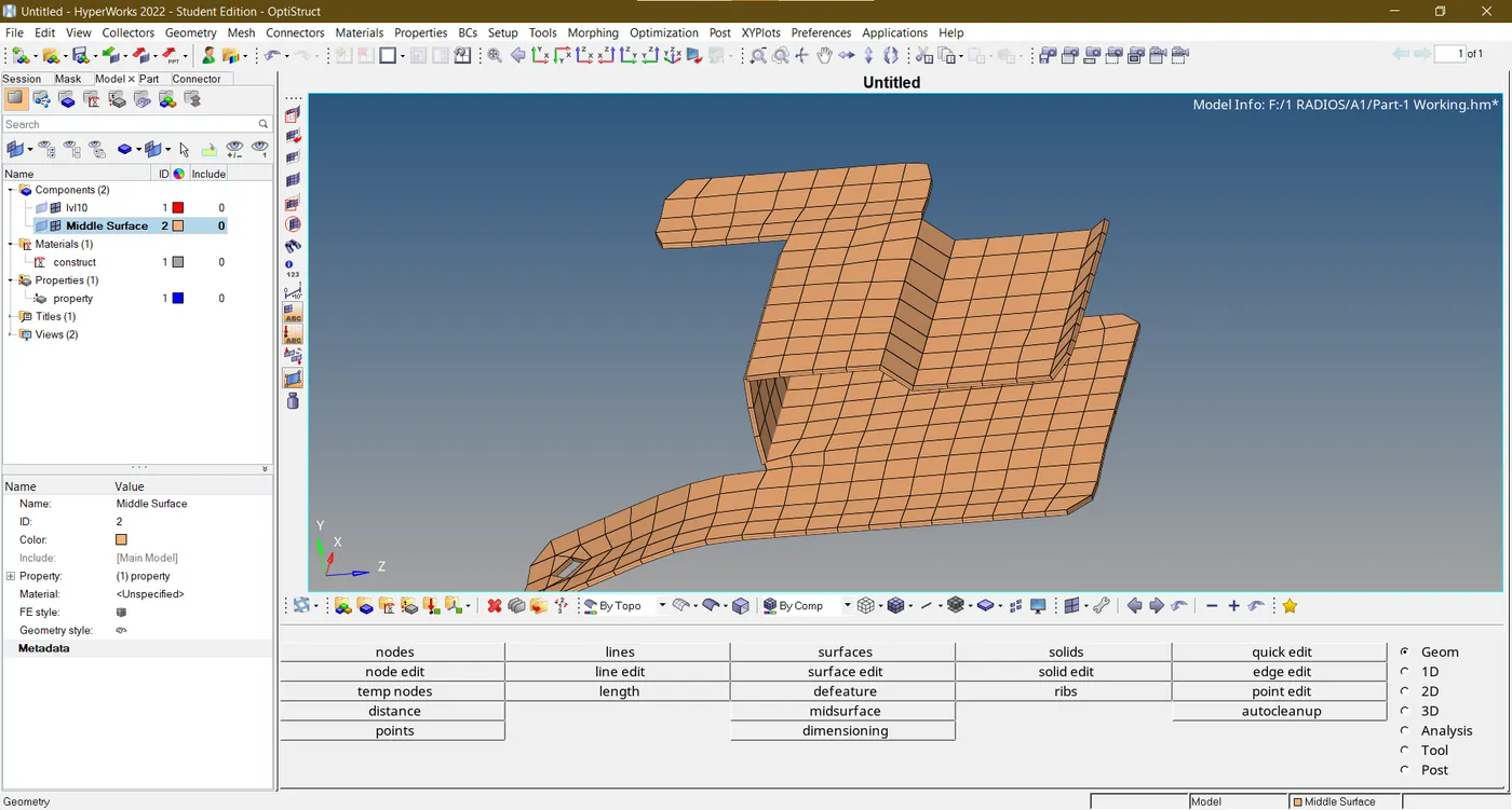
MODEL-2
- The pre-processing stages are repeated likewise done in Model 1.
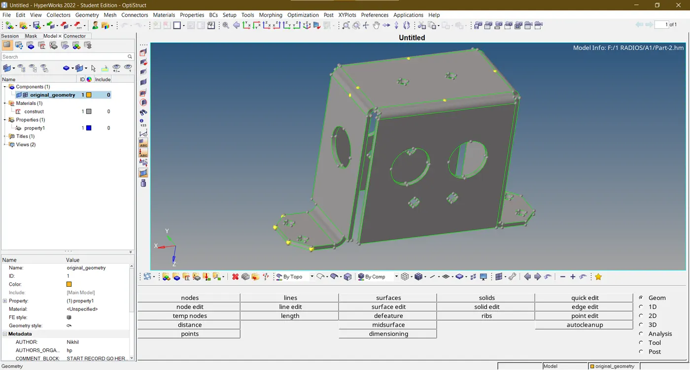
- The model is symmetrical so it is divided into two components to save time for meshing up ahead.
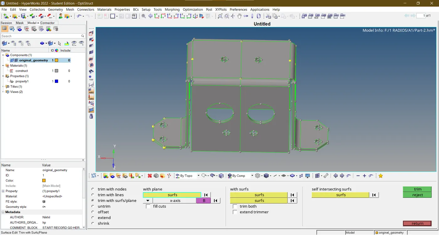
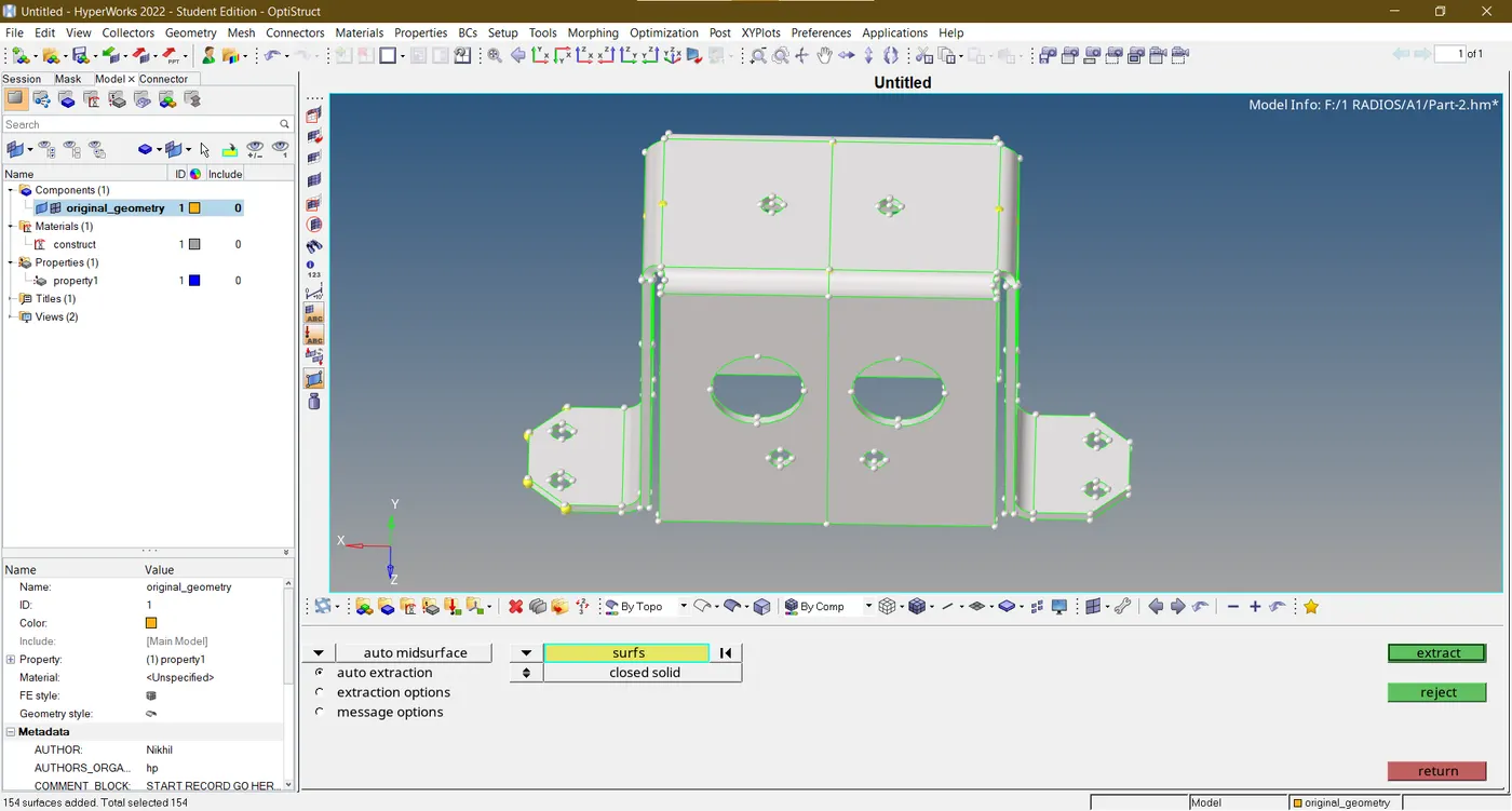
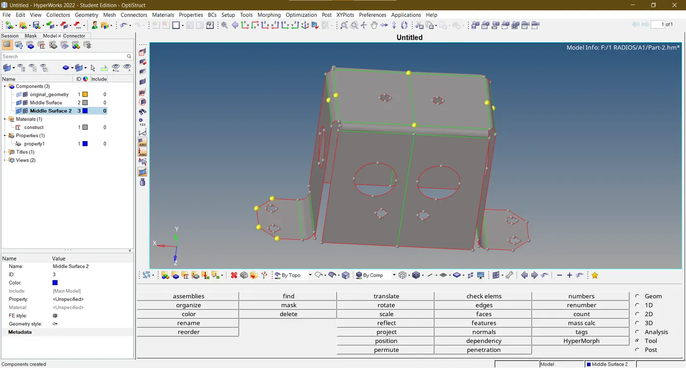
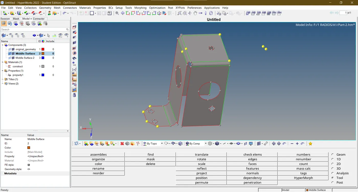
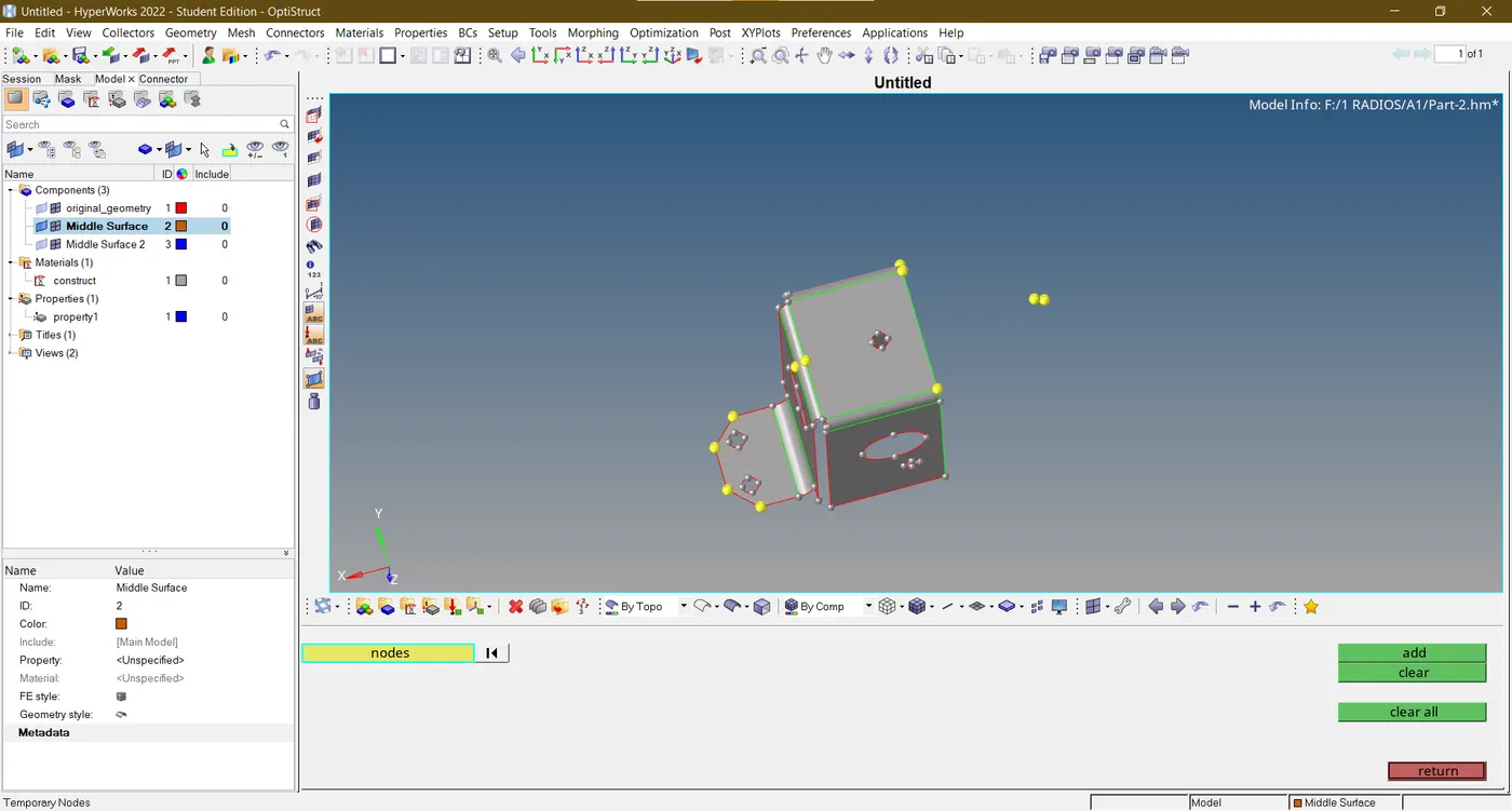
- The washer splits are created around bigger holes and holes with diameter below 5mm are filled with surfaces.
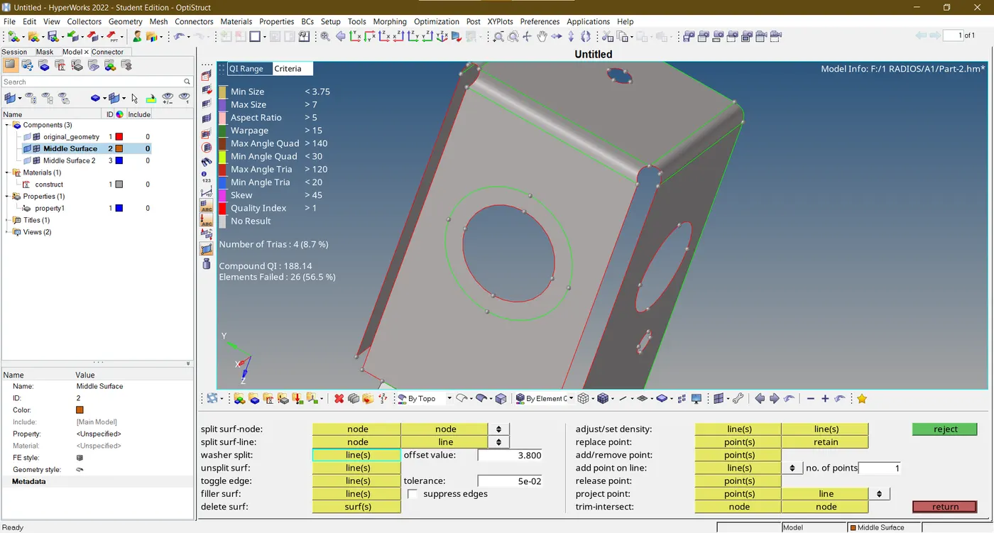
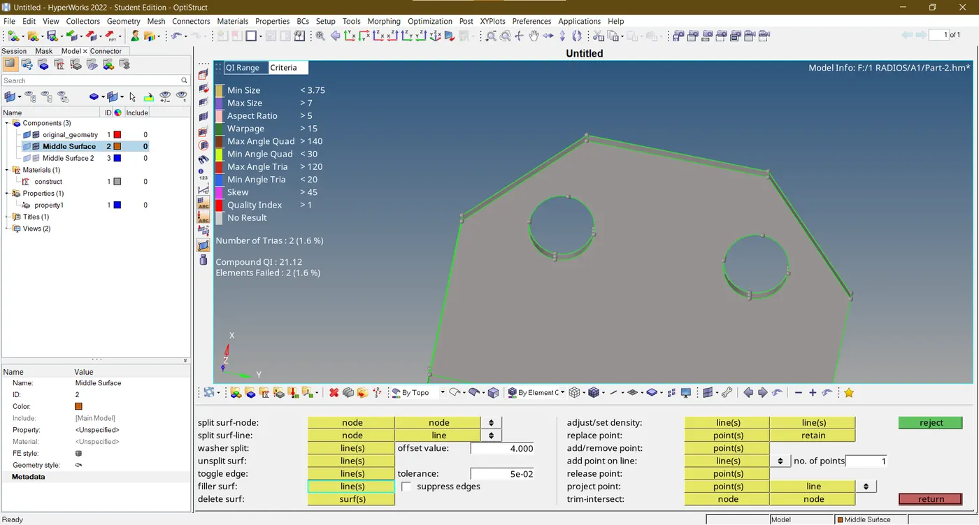
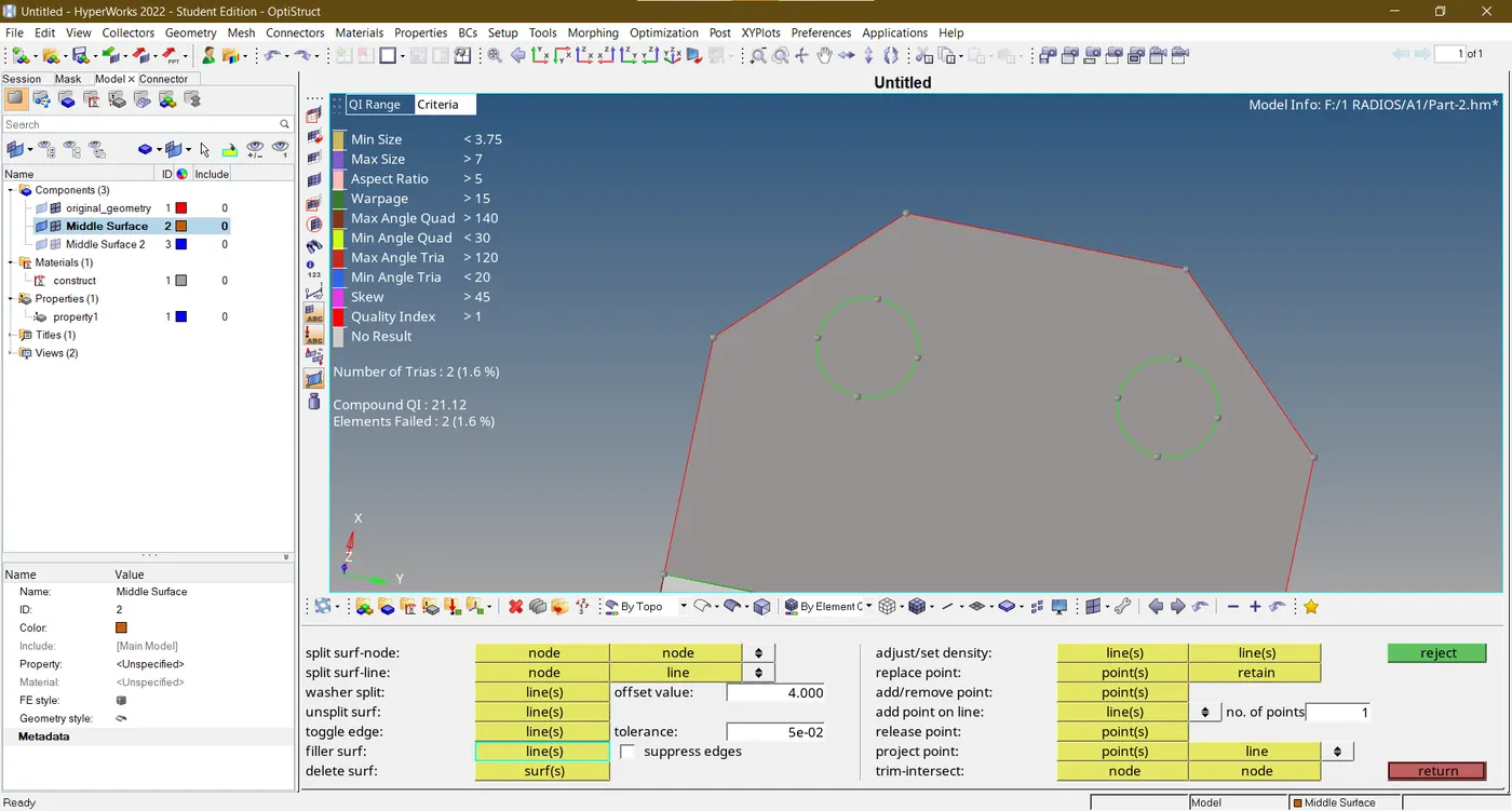
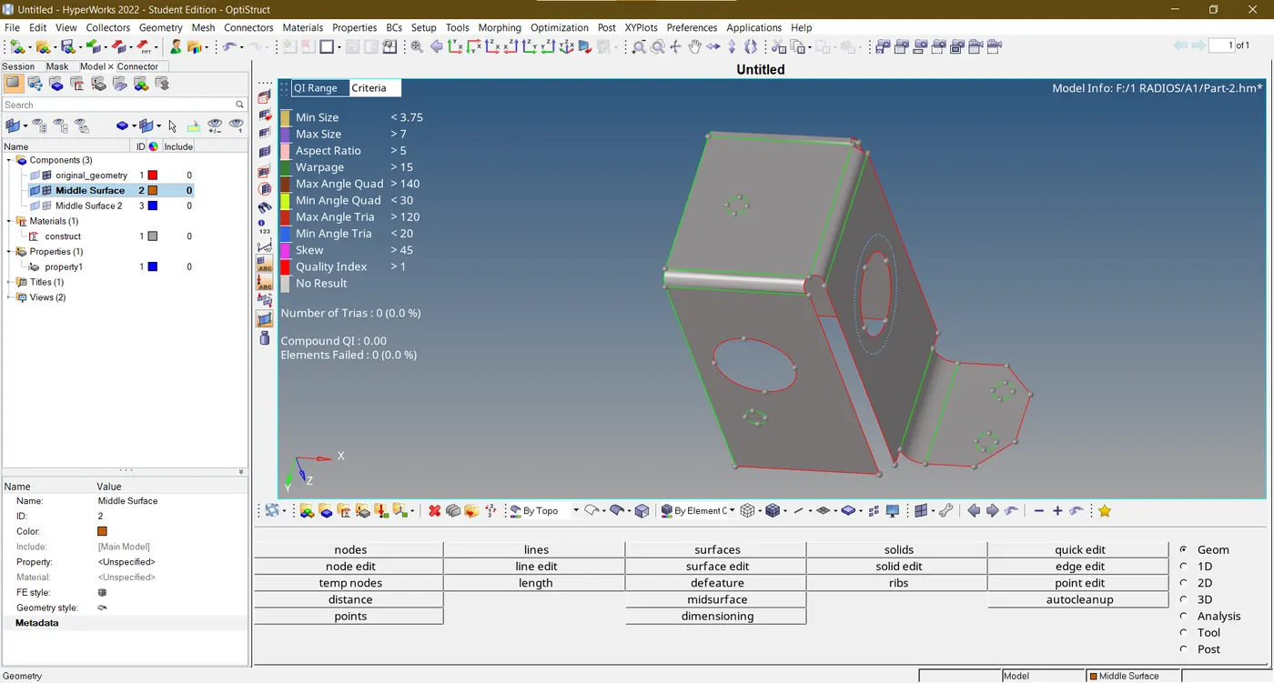
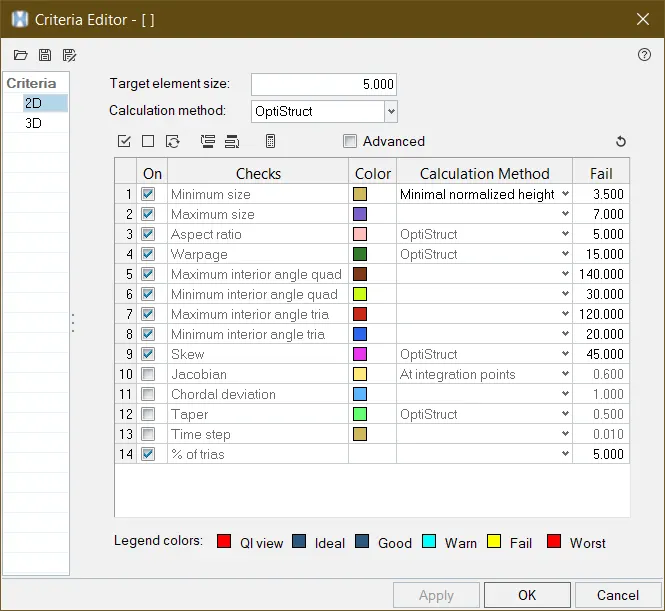
- The quality criteria is inputted as per the given parameters and the meshing phase is initiated.
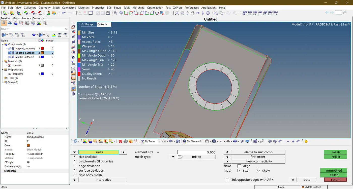
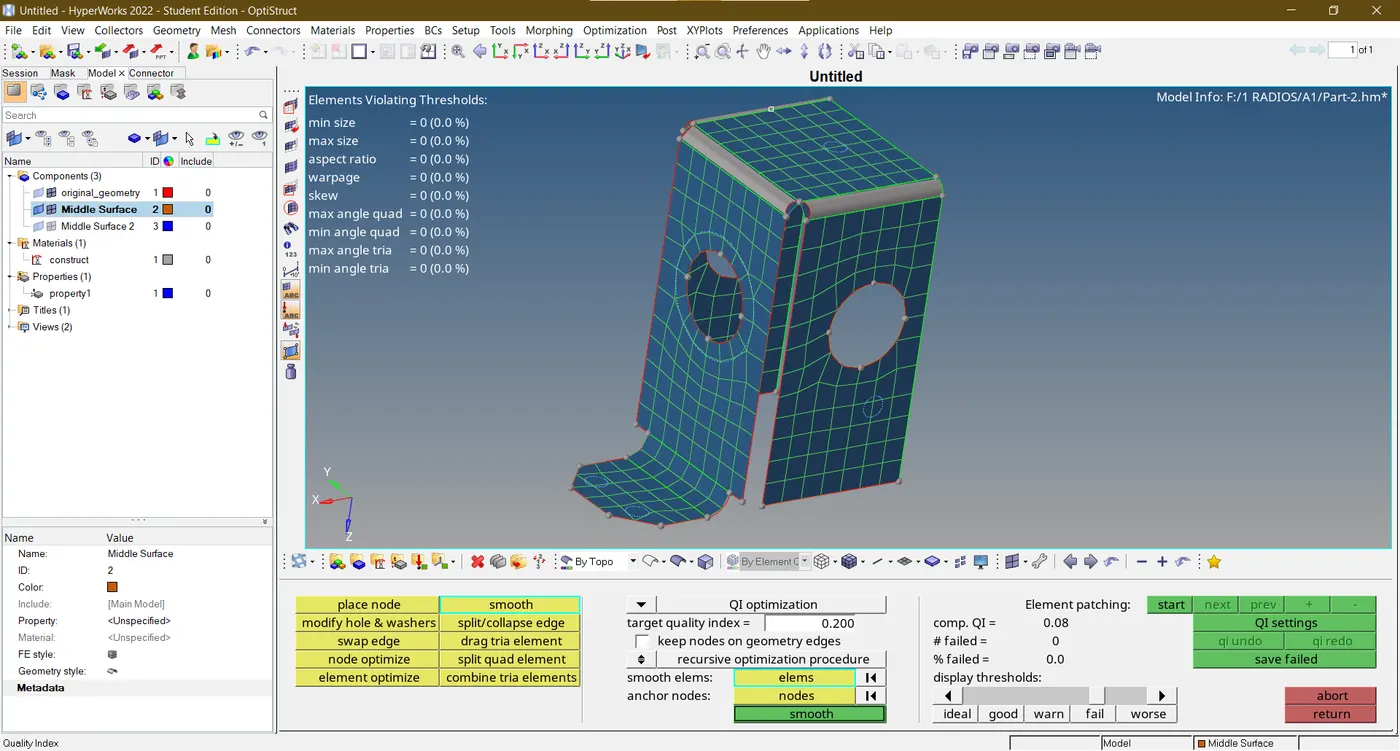
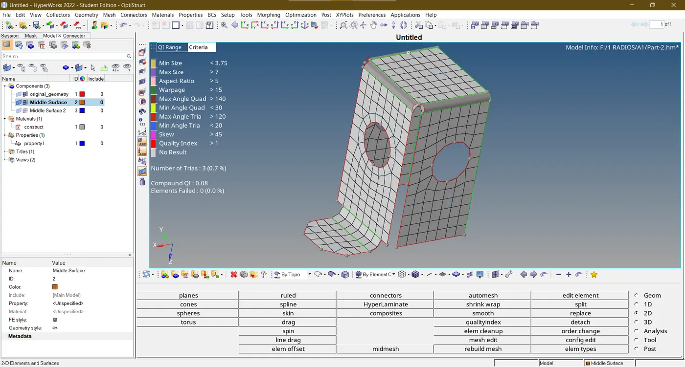
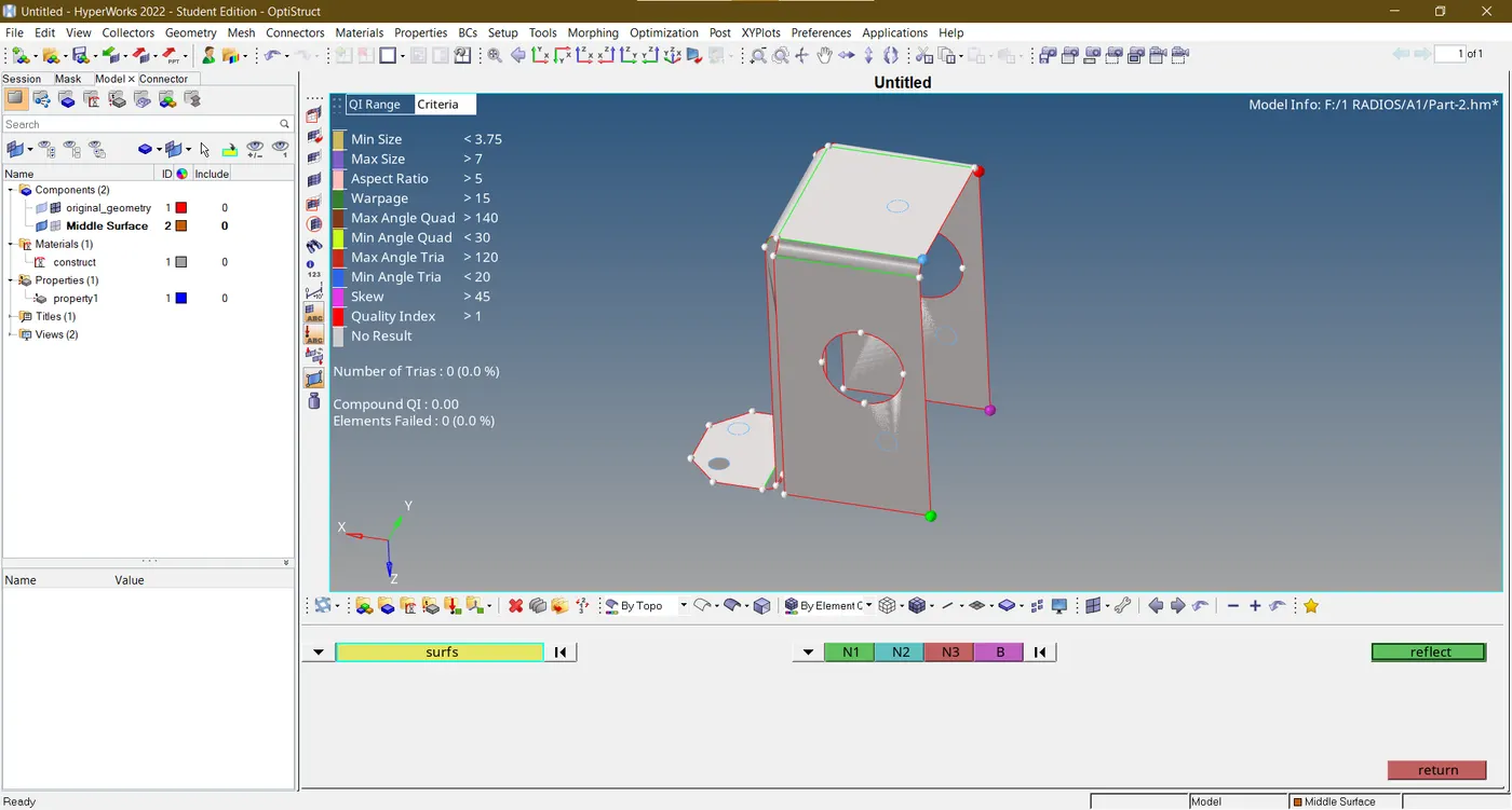
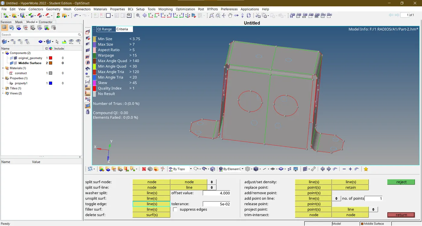
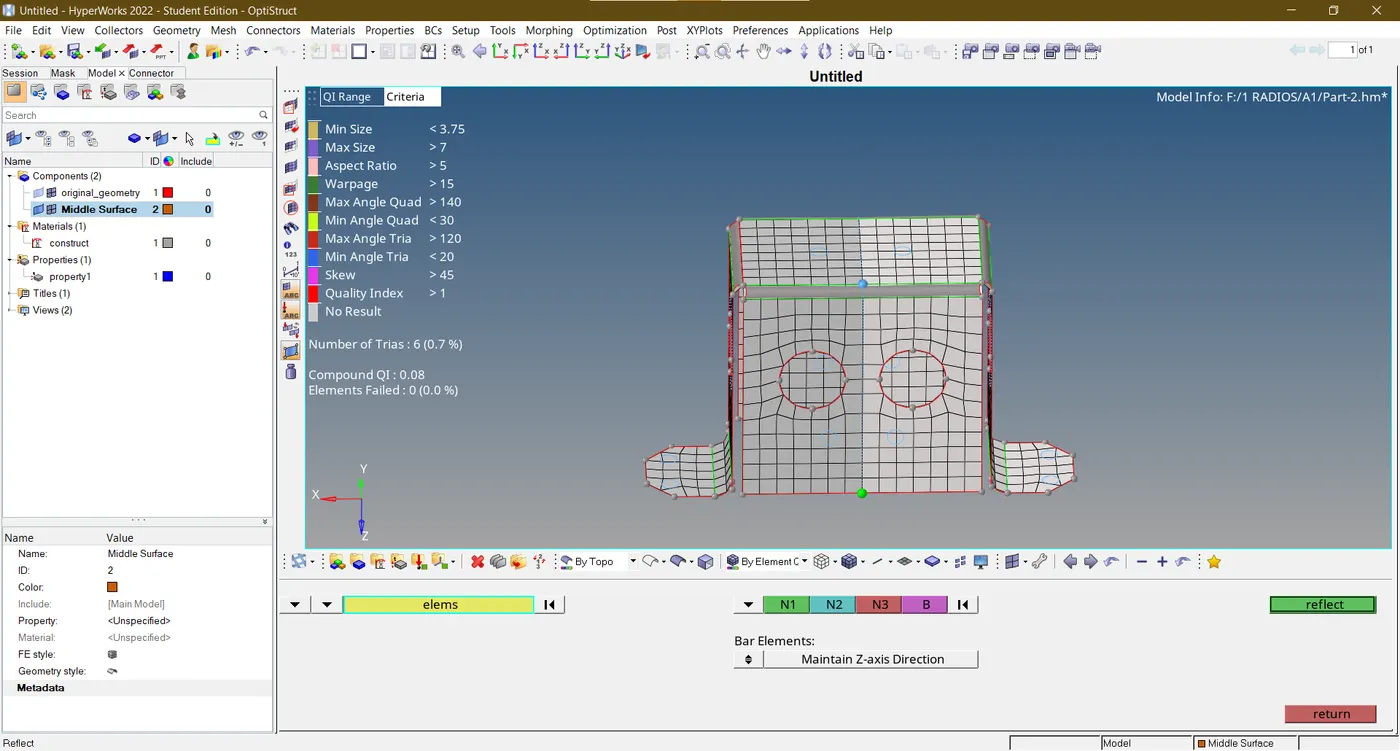
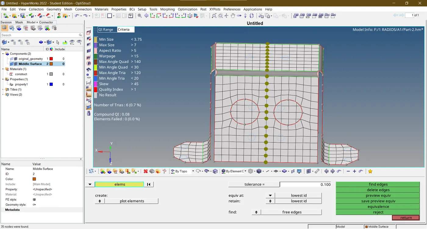
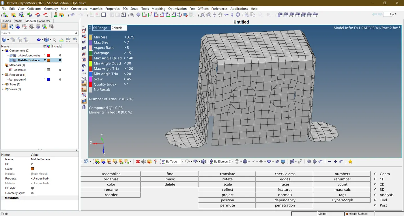
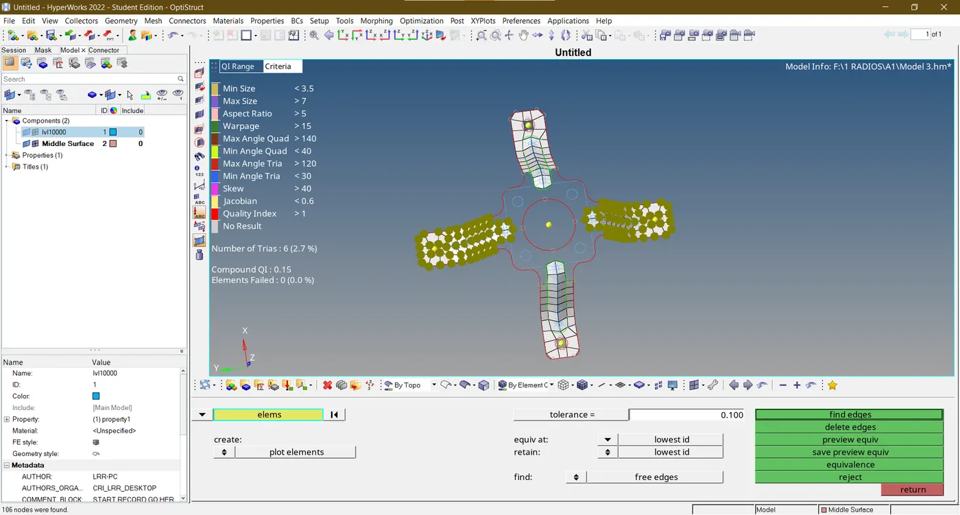
- The gaps are present between the nodes of elements which are generated using the reflect option. It is fixed by using the equivalence option using the edges tool in the panel bar.
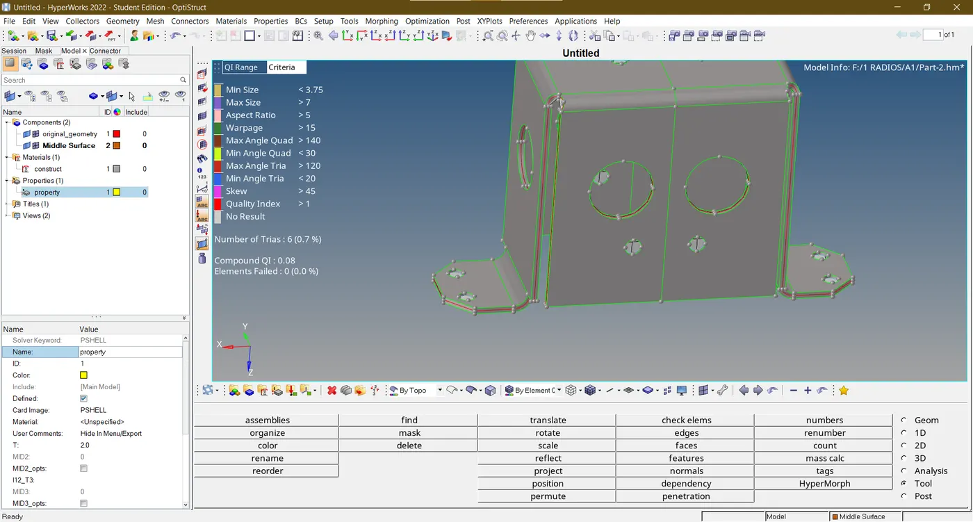
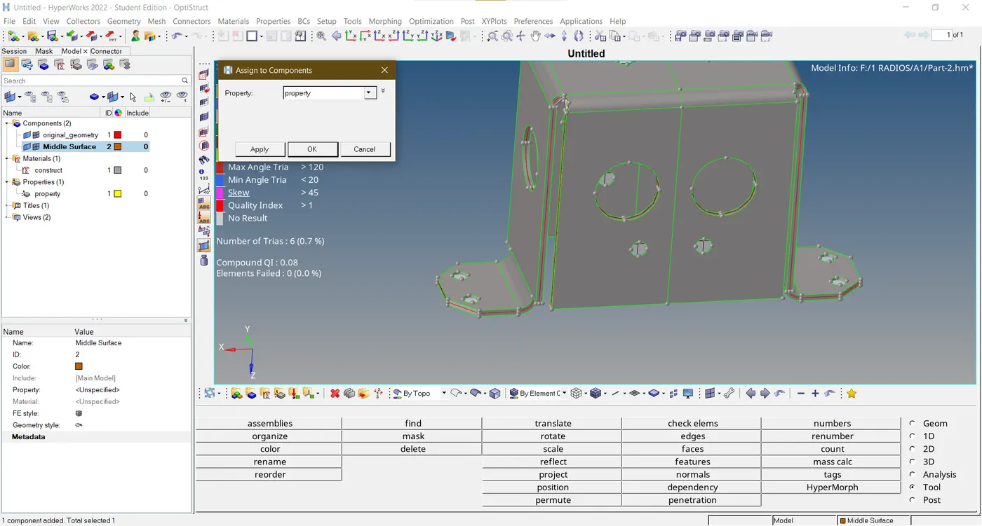
- The final image of the model is displayed below.
MODEL-3
- The same setup is applied to this model as done earlier in Models 1 and 2.
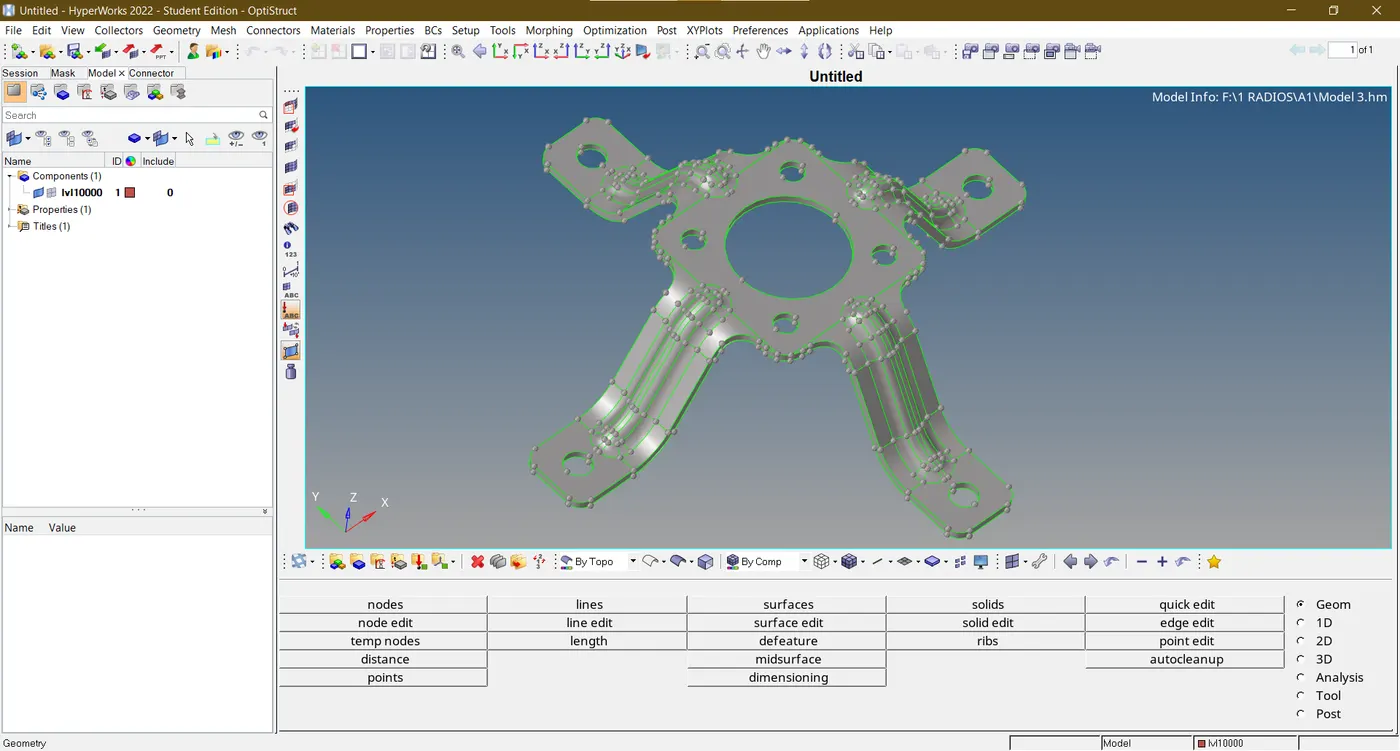
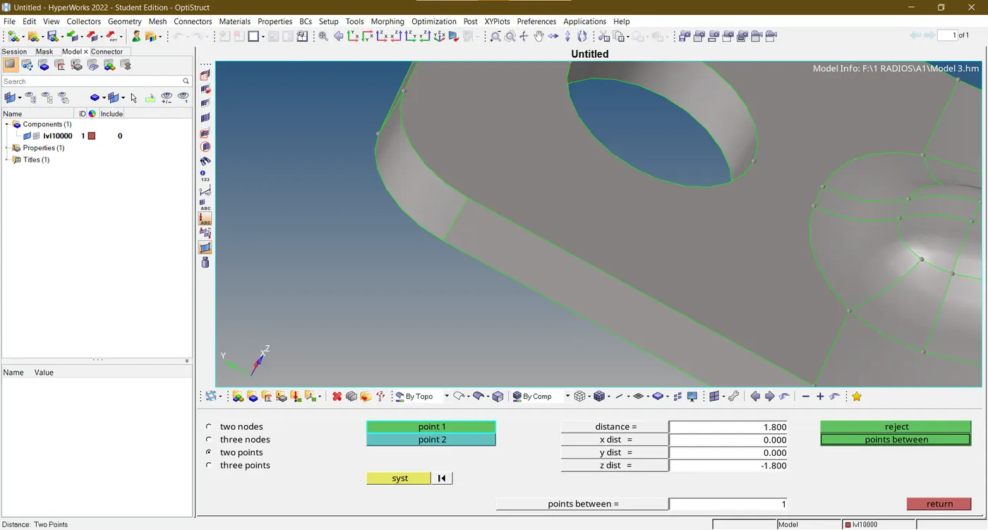
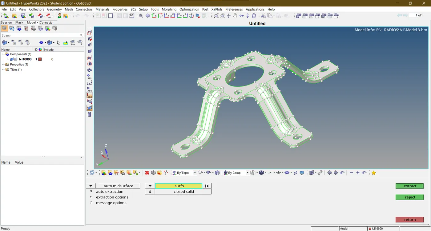
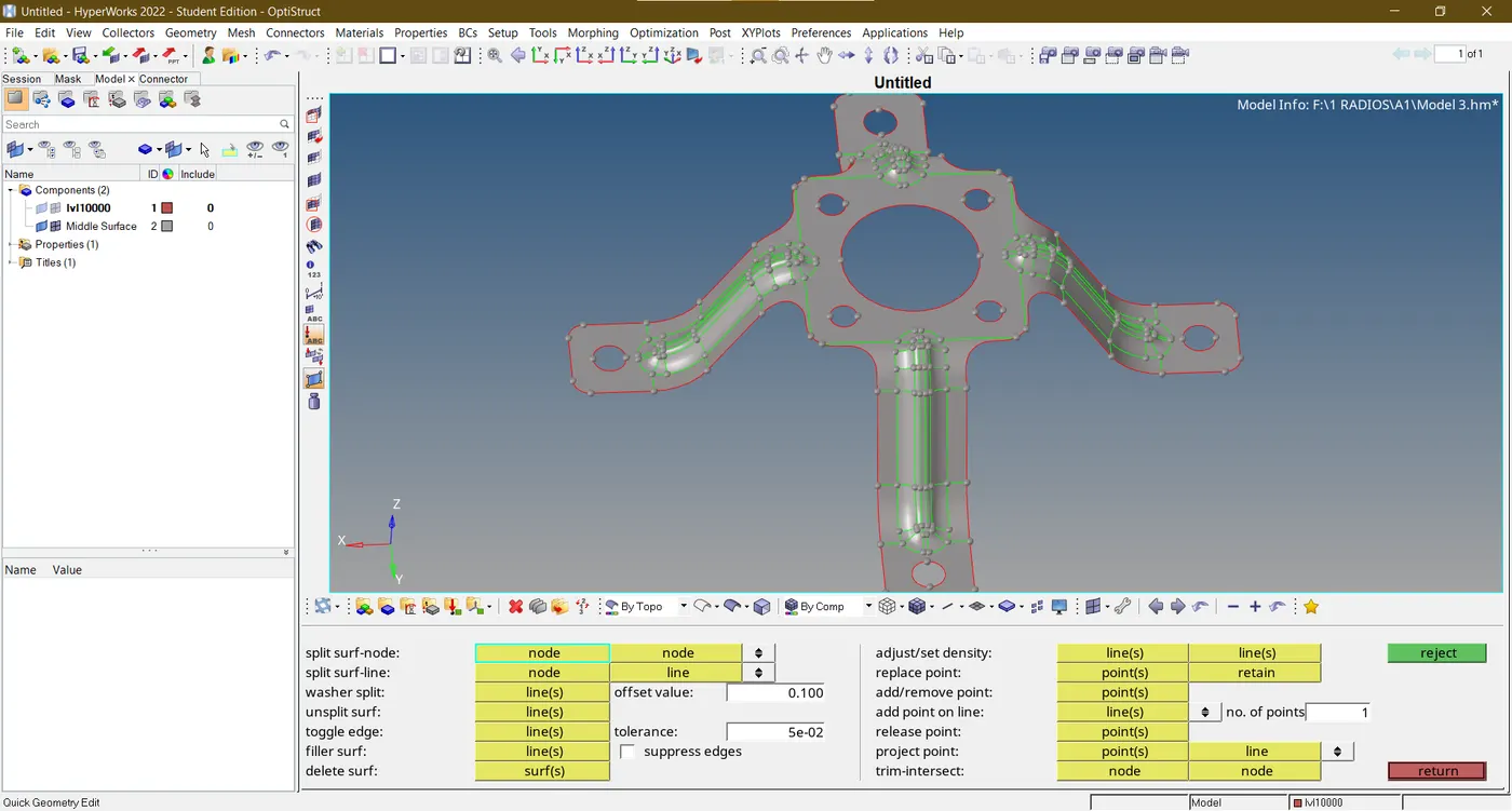
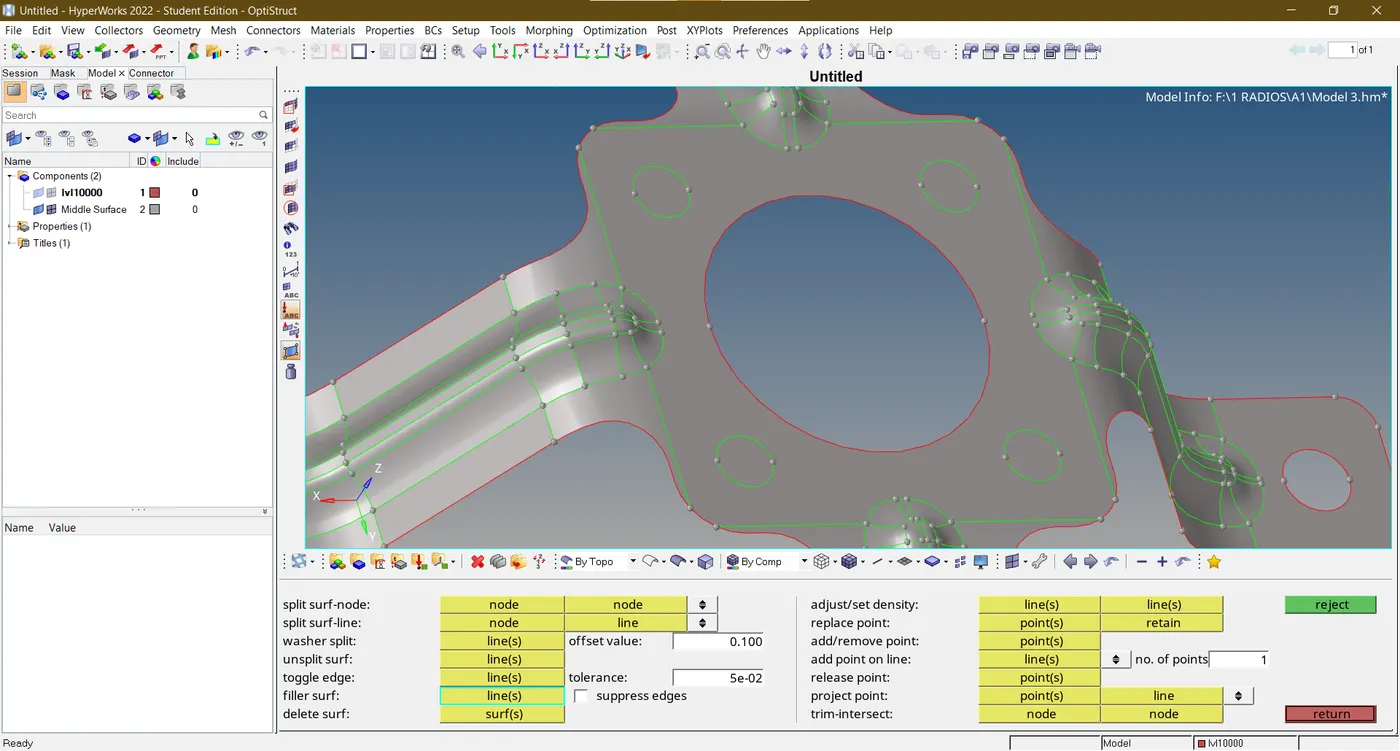
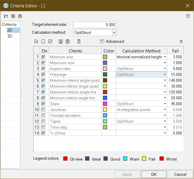
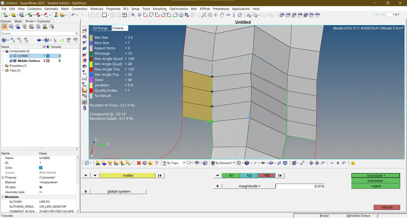
- The translate tool is used to fix quality errors by displacing one of the nodes of failed elements.
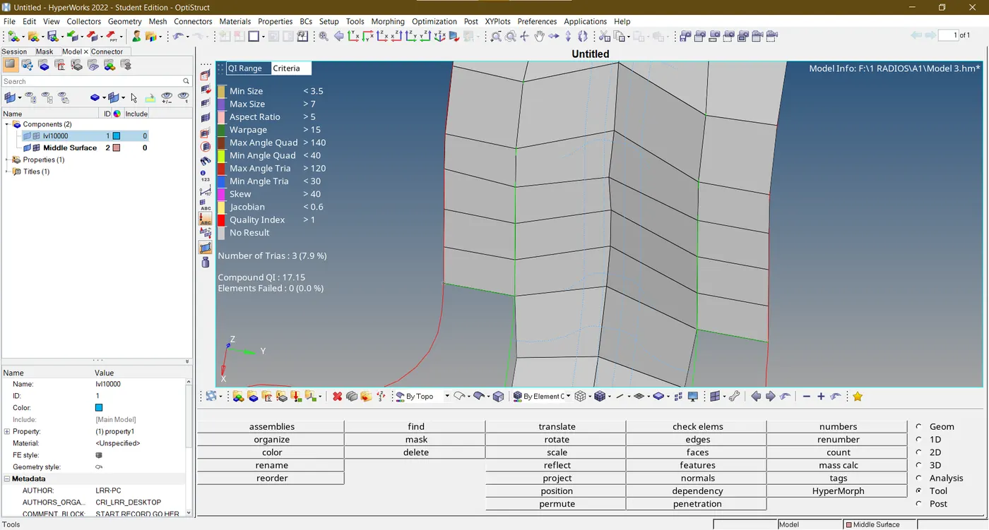
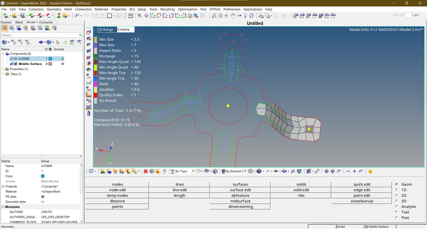
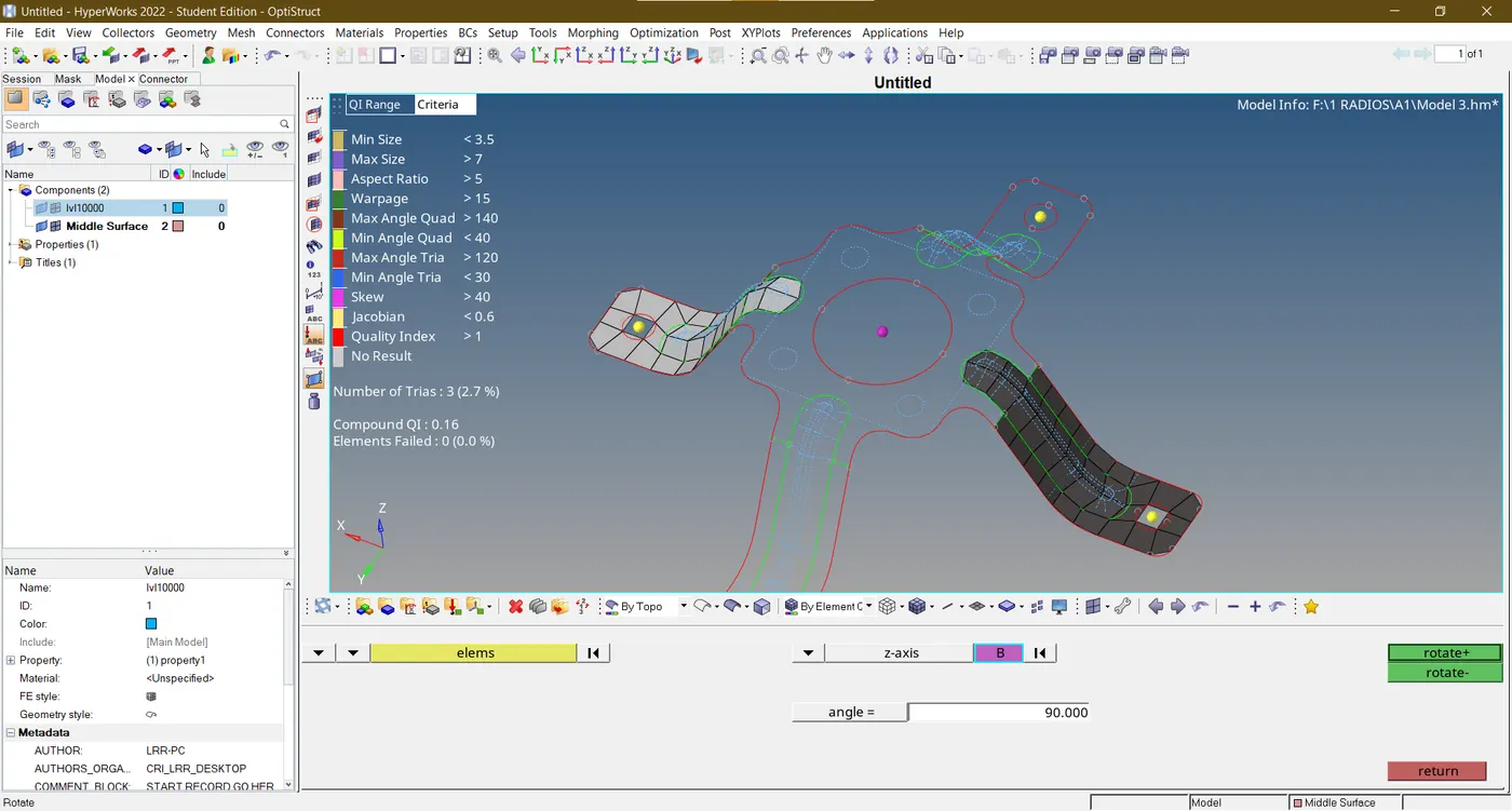
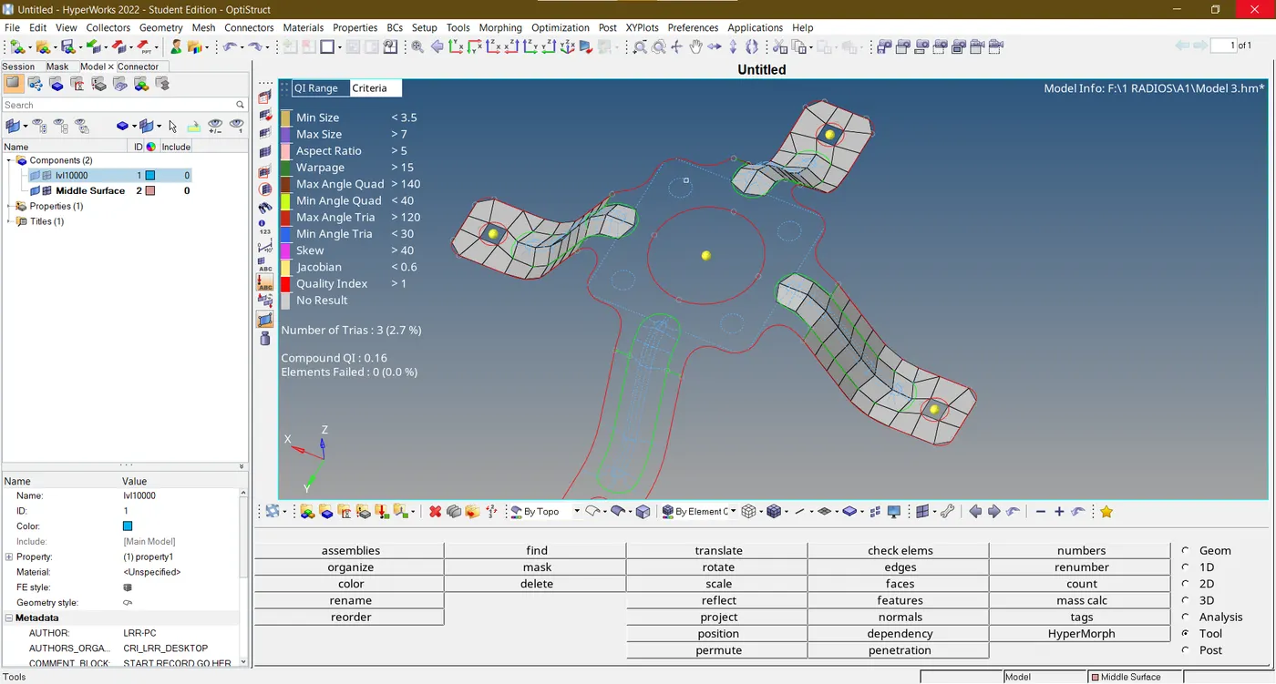
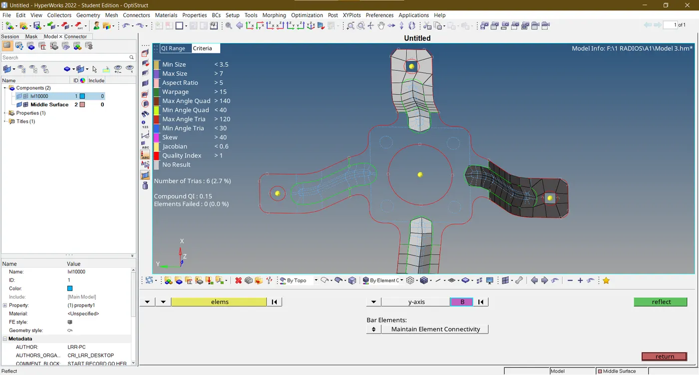
- Since this model is symmetrical the rotate and reflect tools are used to copy mesh appropriately on fillet areas.
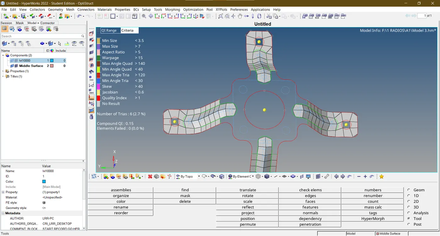
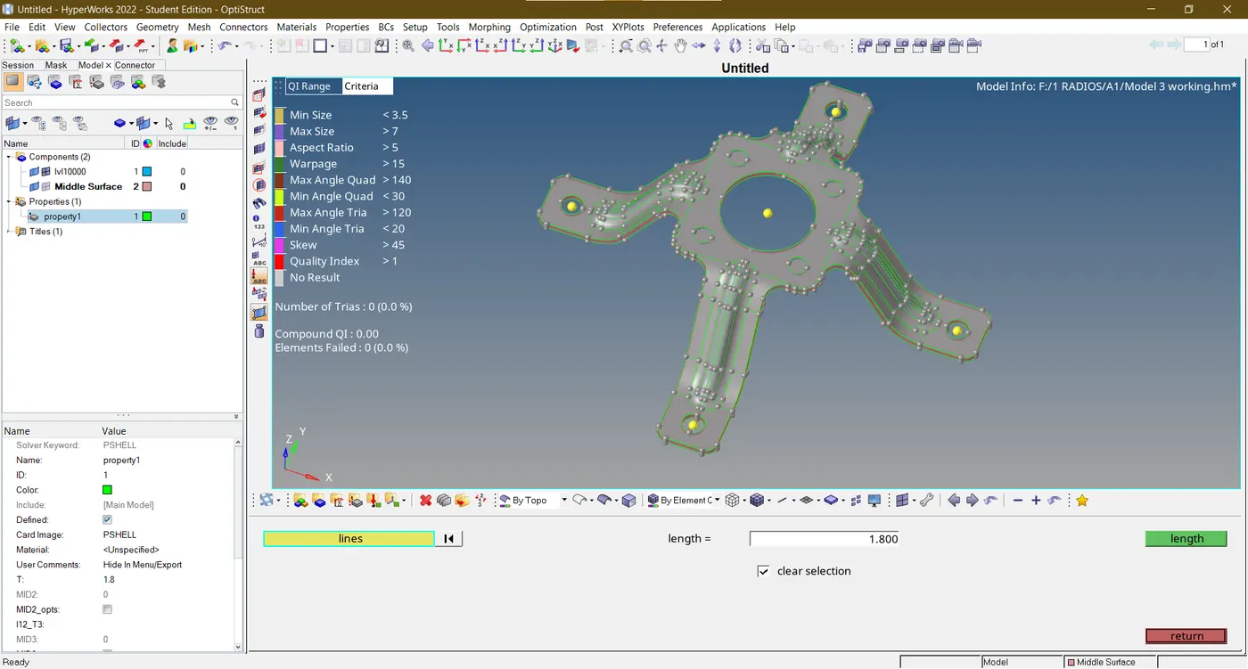
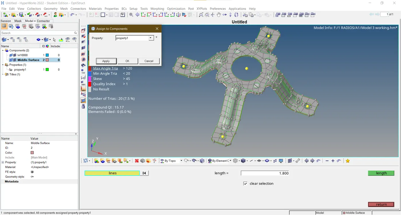
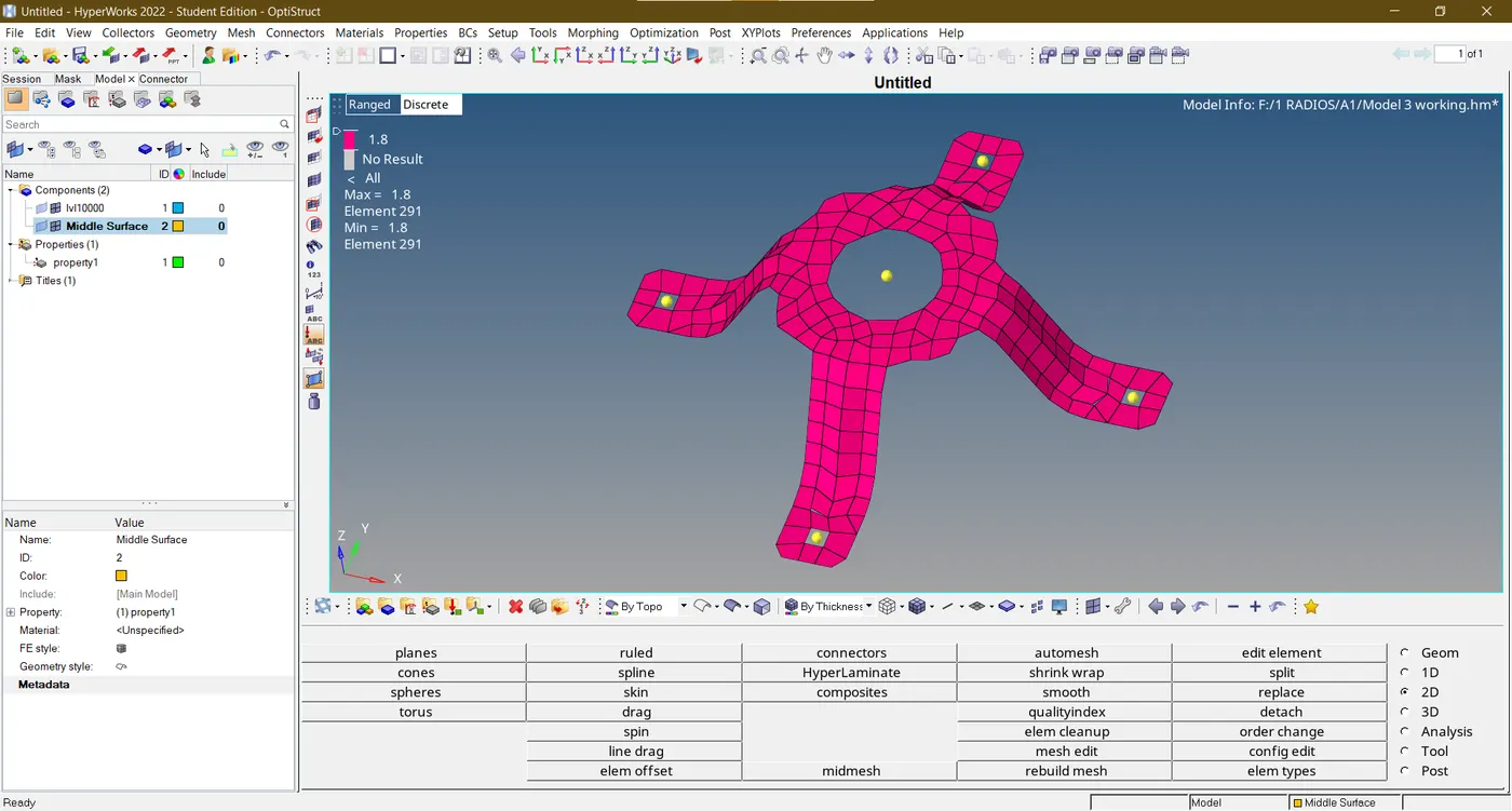
- The final image of the model is displayed below.
CONCLUSION
- This project provided an excellent assessment of the use of hypermeshing for mid-surface extraction and meshing on a sheet metal component.
- As meshing in this component advances, several defeaturing strategies are learned.
- The model is handled with appropriate quality criteria parameters that provide useful information about our performance during the hyper mesh pre-processing phase.
- The model is shown in detail in a three-dimensional arrangement according to the thickness assignments for each entity.