Assignment 7-Side Pole Crash Simulation Challenge
SIDE POLE CRASH SIMULATION USING RADIOSS
INTRODUCTION
The conventional robust procedure used experimental testing techniques, putting sensor-equipped dummies on the driver's (and passenger's) seat, rather than relying on computers and models. The most well-known kind of test is an automobile frontally impinging on a solid (cement) wall. Models that were removed from the market due to inadequate safety ratings were influenced by these tests.
Later, computer-aided engineering—car simulation run on specialized computers to improve comprehension of crashworthiness and replicate it more accurately, particularly about design modifications—became helpful in real crash testing. Changing CAD files and starting a new simulation is not the same as replacing a physical part and conducting a new test.
Because it is based on well-established physical modelling and has a reliable methodology in place, the finite element model yields faster results and aids in accelerating development with feedback from business datasets.
Subsequently, a great deal more tests were created, like roll-over, side-impact, and side-pole-impact tests. The finite element method assisted in addressing a lot of design modifications, enabling engineers to compute the optimal car models.
A computer-based method for simulating and analyzing how cars and their parts react to collisions is called a crash simulation. By simulating actual crash scenarios using cutting-edge software, these simulations give engineers a virtual testing ground where they can evaluate the performance and safety of various car designs.
A virtual car crash simulation can achieve great realism in simulating structural deformations, vehicle behaviour, and occupant dynamics during crashworthiness testing when it is carried out using advanced FEA (finite element analysis) and other simulation techniques. These simulations can offer comprehensive numerical assessments and visual insights into vehicles' integrity, safety, and performance.
To reproduce different collision scenarios, engineers specify impact conditions, angles, and speeds when defining crash scenarios.
Certain crash test scenarios are required by regulatory testing from US and EU authorities, especially the European New Car Assessment Programme (Euro NCAP) in Europe and the National Highway Traffic Safety Administration (NHTSA) in the US. These crash test scenarios guarantee that automobiles adhere to safety regulations. They were adapting simulation to various regulatory standards and taking real-world unpredictability into account present obstacles.
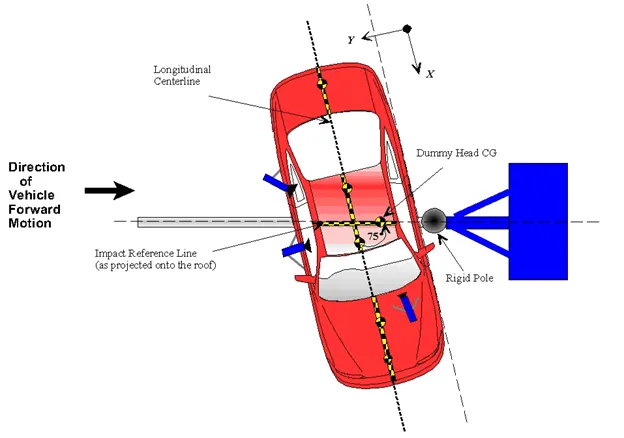
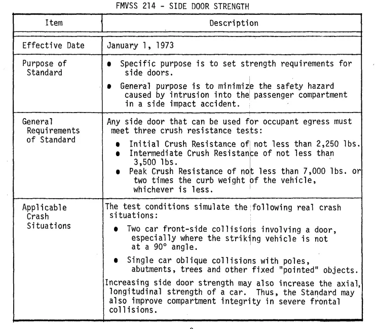
The second most frequent kind of accident is side collisions. When compared to the accident rate, these are the ones that cause the most critical injuries. The occupant's spatial closeness to the deformation zone explains this. For the side impact, there are various test criteria. These include the side crash as defined by the US and European standards FMVSS-214 and ECE-R95, as well as the tests conducted as part of consumer protection initiatives. According to Euro NCAP, there is a Pole Side Impact test in addition to the side impact test itself.
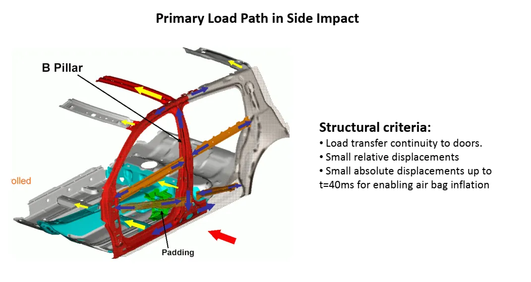
To develop safety restraint systems, side-crash simulations on sledge systems are conducted. These tests start early in the vehicle's overall development. However, prototype parts are expensive and not always readily available at this time. Compared to a destructive test technique, significantly fewer parts are required for the non-destructive sledge test. A seat, for instance, can be used repeatedly, and the door construction and trim can withstand numerous tests. A new test may be put up quickly because a lot of the test components can be reused.
The vehicle used in the NHTSA's side-impact test is impacted on the left side by a 3,015-pound car moving at 38.5 mph. This kind of situation is similar to what might occur if you are struck from behind at an intersection. The driver and left rear passenger have separate side-impact star ratings. Before 2011, the score was determined only by a chest-injury metric for models. The head, chest, abdominal, and pelvic data for the driver and the head and pelvis injury for the rearseat passenger are the score criteria for cars made in 2011 and later.
Compared to the NHTSA, the IIHS side-impact test is more stringent. In contrast to the NHTSA's 3,015-pound hitting barrier, the test employs a heavier 3,300-pound barrier. To replicate a car being struck on the side at a 90-degree angle by a typical-height SUV or truck, the IIHS barrier also strikes higher up on the tested vehicle. The head, neck, chest, abdomen, pelvic, and leg injuries are the foundation for the IIHS score.
In the IIHS side-crash test, the two dummies are either a 12-year-old teenager or a petite adult female. The driver is one, while the passenger on the left is the other. The IIHS and NHTSA utilize a dummy that mimics an average-sized adult male during other crash tests.
OBJECTIVES
Neon side crash -BIW
- Check the unit system and follow [Mg mm s] or [Kg mm ms].
- Create an appropriate interface, friction 0.2, and recommended parameters.
- Make sure of no penetration and intersections.
- Create a rigid pole with friction of 0.1 per the FMVSS 214 standards.
- Compare the model weight with the reference model and use added masses to reach the target weight of 700kg while getting CG about the required range.
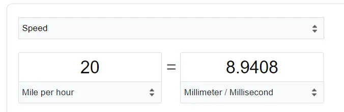
- Initial velocity - 20mph, as per the standards.
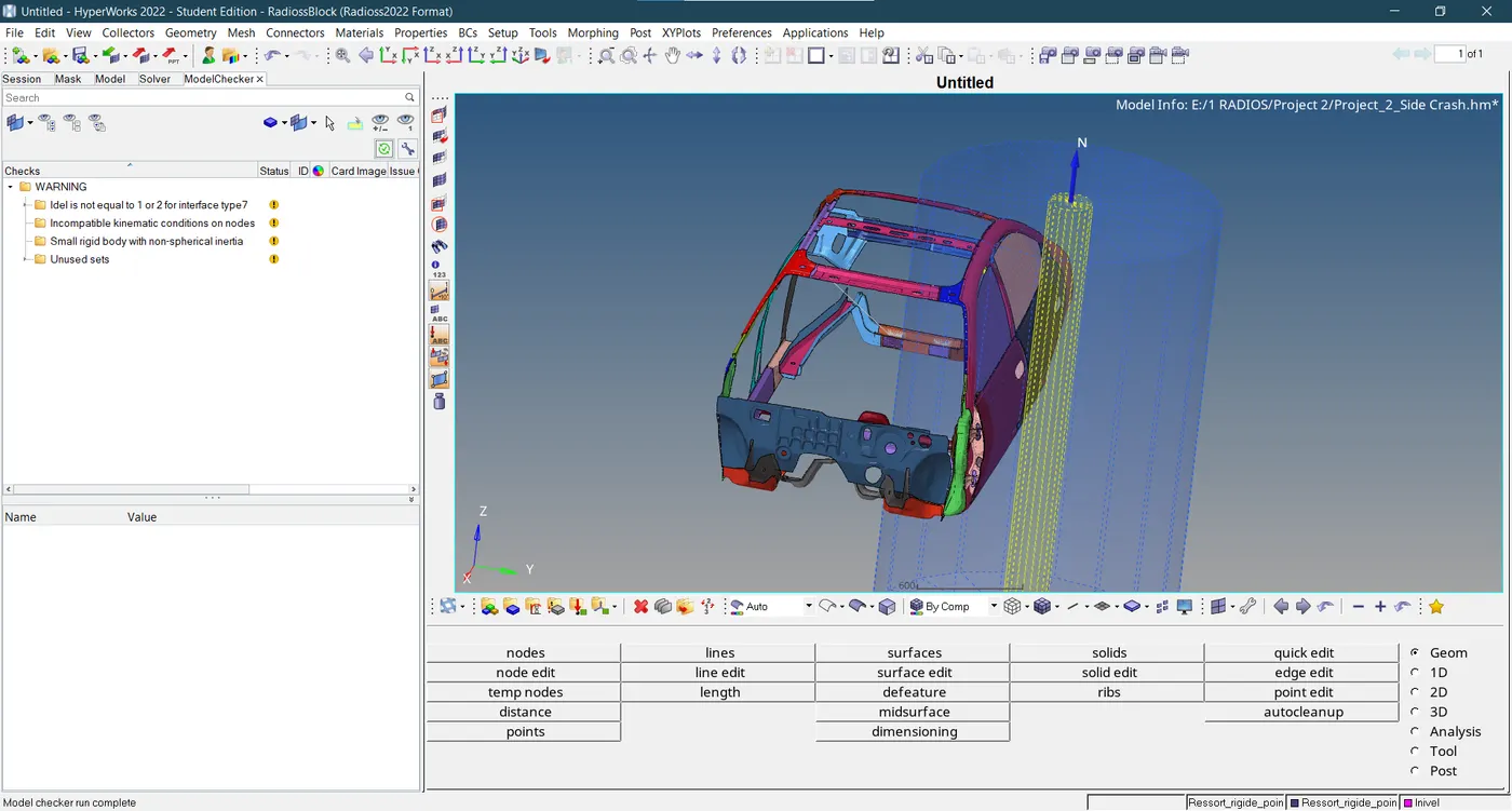
- Use a model checker to ensure good quality.
- Timestep:0.5 to 0.1 microseconds.
- Run 80ms.
Output requests:
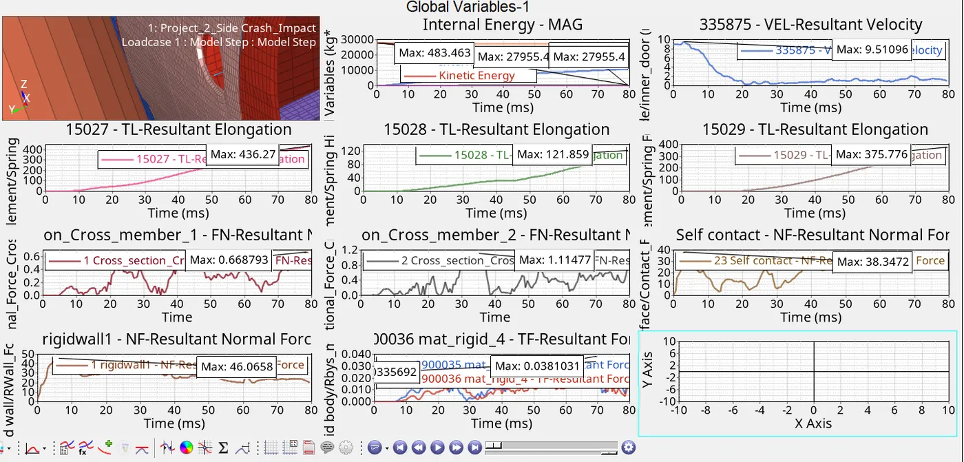
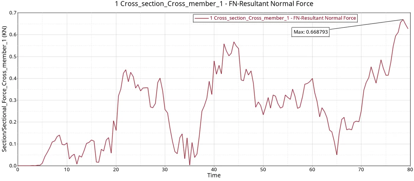
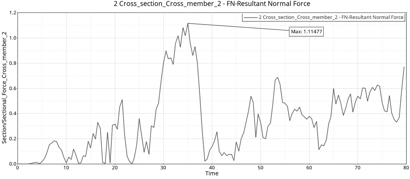
- Sectional force in the cross member.
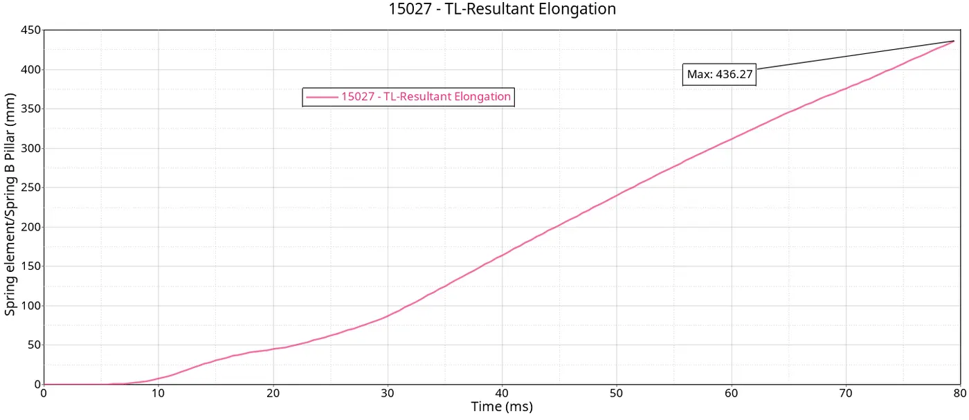
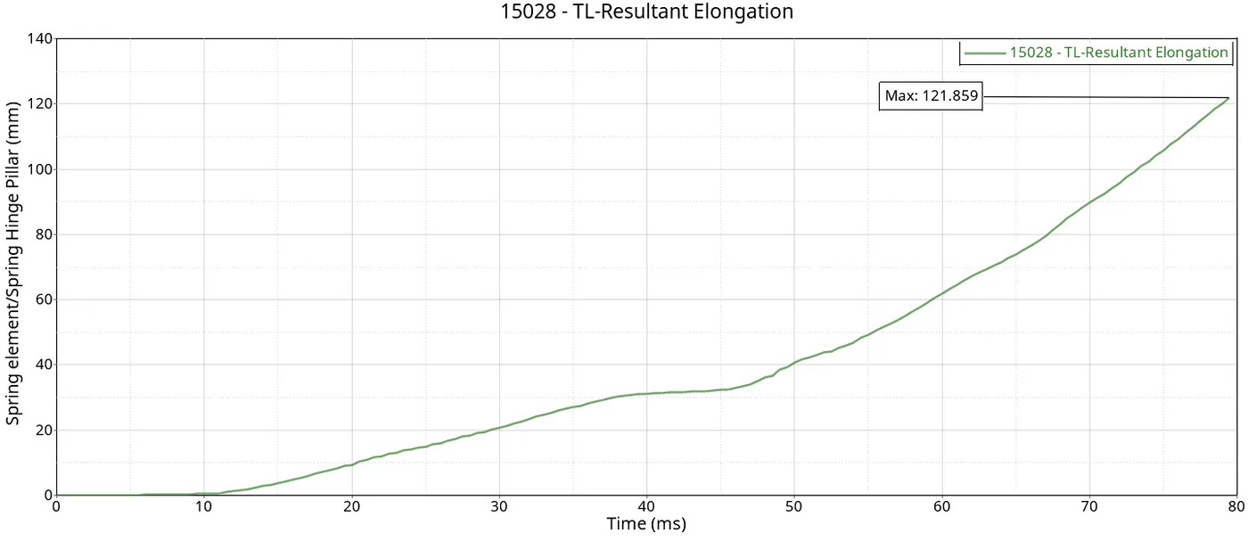
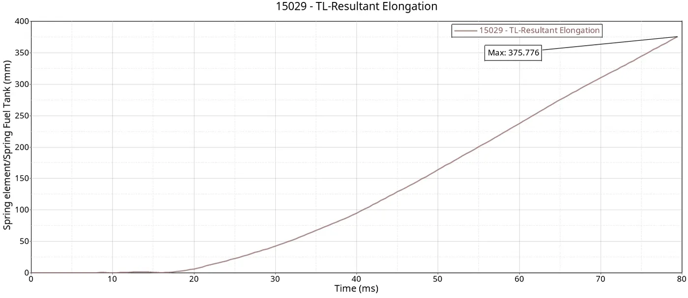
- Intrusion at B pillar, hinge pillar and fuel tank region. Provide recommendations on what can help to reduce Fuel tank intrusion.
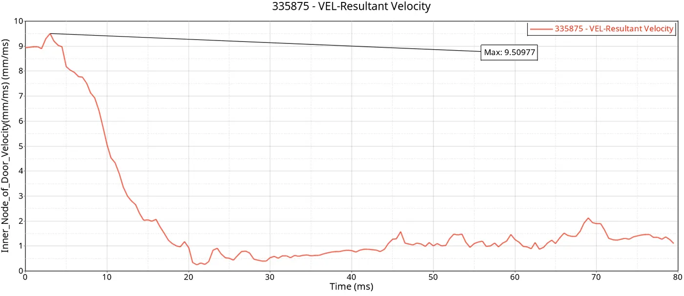
- Peak velocity of an inner node of the door.
PROCEDURE
- In this Project, the cabin FE of the Neon model is being imported in RADIOSS hyper mesh as .rad format using an import solver deck. The model is thoroughly examined and evaluated to further operate for side pole crash analysis.
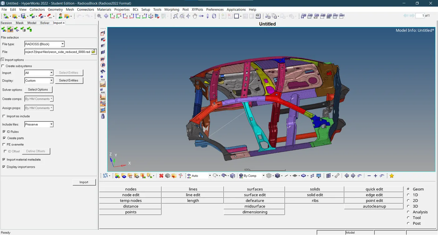
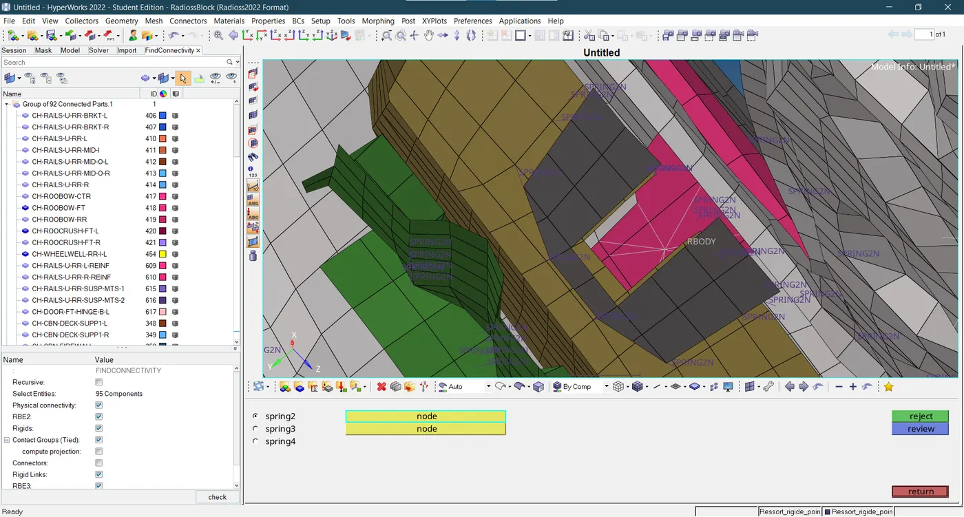
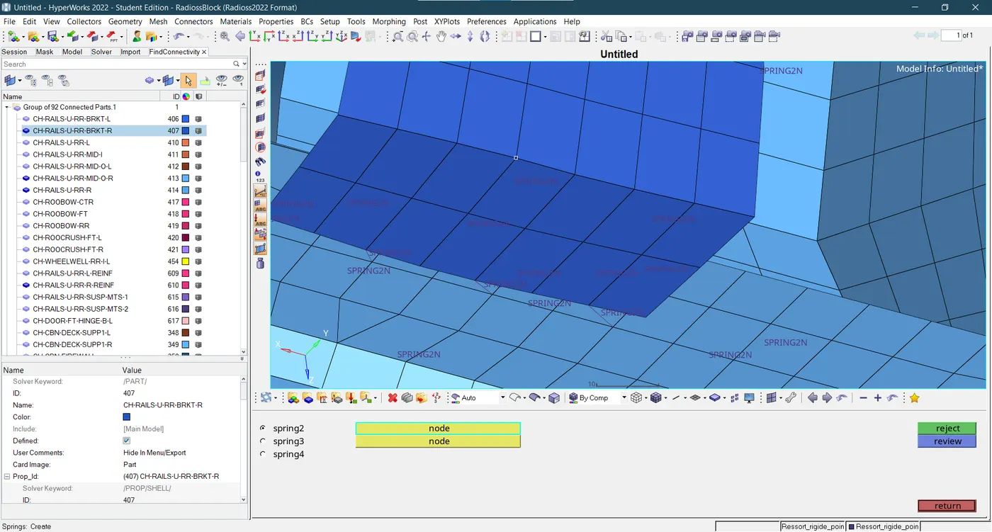
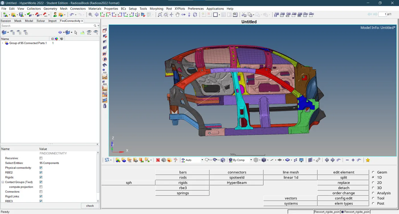
- Using the find connectivity tool we observe a lot of components are not connected. The inner and outer B-pillar components and some components in the fender area are not connected with the rest of the components of the car model. So the 2 noded spring connectors are used to deploy connections to the corresponding components.
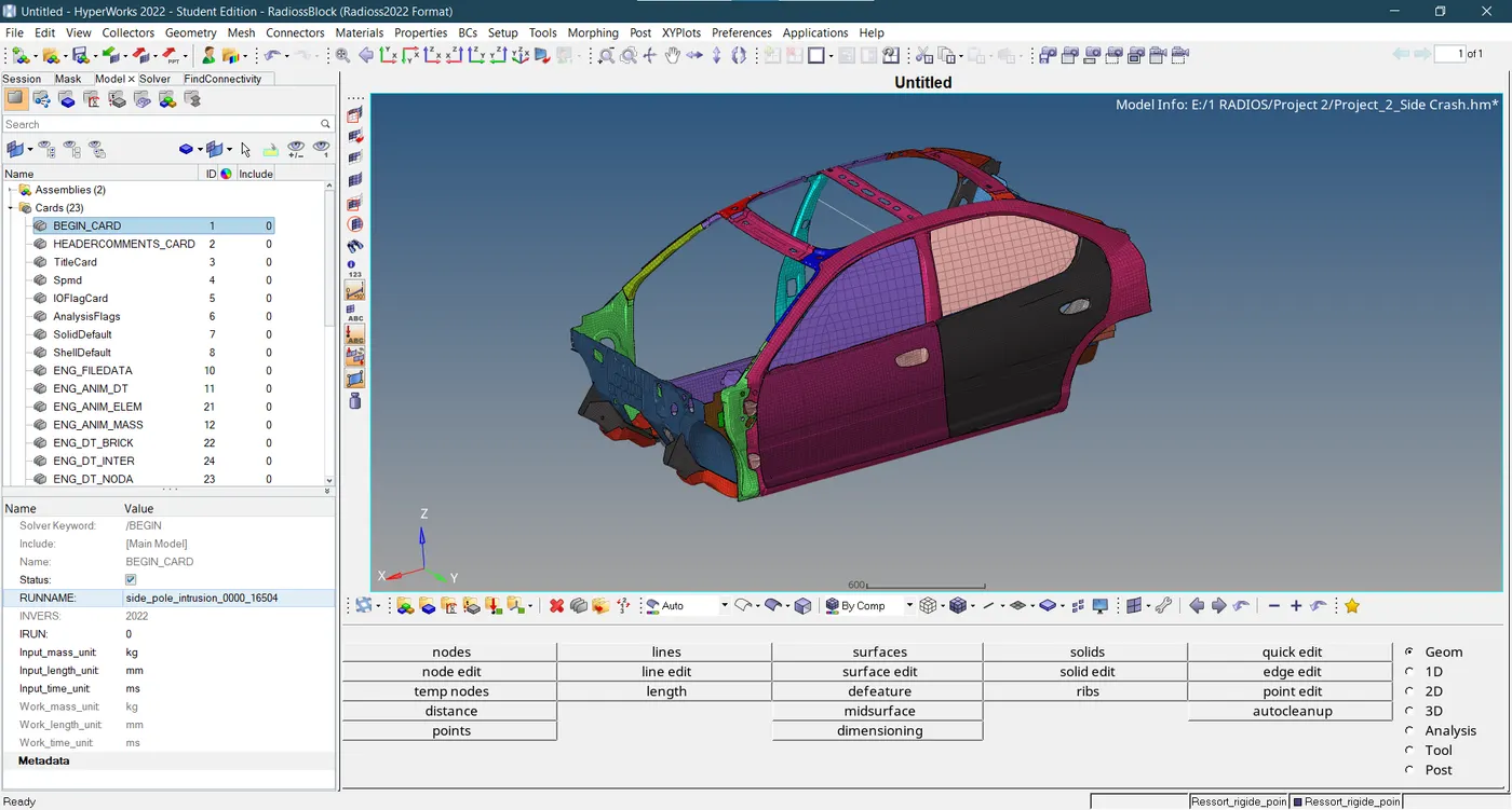
- Throughout the analysis in Begin_card, the standard unit system of kg-mm-ms-KN-MPa is utilized as indicated below.
- A rigid wall is a nodal constraint that prevents nodes from penetrating the wall by applying it to a set of secondary nodes. The acceleration and velocity of the secondary node are adjusted if contact is found.
- To ascertain if a secondary node is in contact or not, there is no gap. Only when the secondary node makes contact with the hard wall surface does contact occur. Depending on the flag Slide, the secondary node's tangential velocity can also be changed. The model allows for pure sliding during contact with the default value (=0). The secondary nodes are "tied" in the tangential direction if the value is 1, which prevents sliding. When set to 2, the Coulomb model-based friction is activated.
- Both permanent and movable rigid walls are the available options. A moving wall resembles a primary secondary option, but a fixed wall is a pure kinematic condition on all impacted nodes. Every time step, a main node establishes the wall position and applies velocity to any impacted subsidiary nodes. The main node receives forces from the impacted subsidiary node. Momentum conservation is used in the computation of the secondary node forces. Assuming a significant hard wall mass in comparison to the mass of the impacted secondary nodes, the mass of a secondary node is not communicated to a main node.
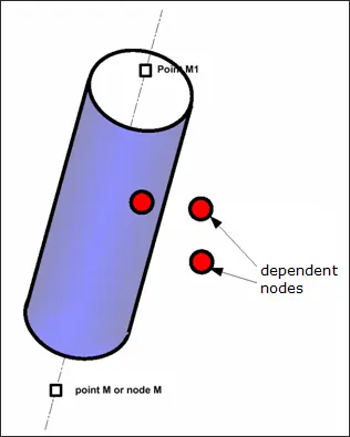
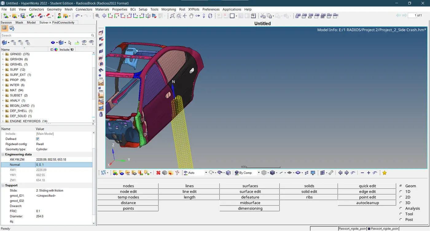
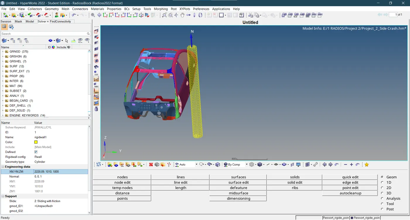
- The type of rigid wall used in the side pole crash analysis is an infinite cylindrical wall. A wall that is infinitely long and cylindrical is called an infinite cylindrical wall. It is defined by a diameter and two points, or one point and one node.
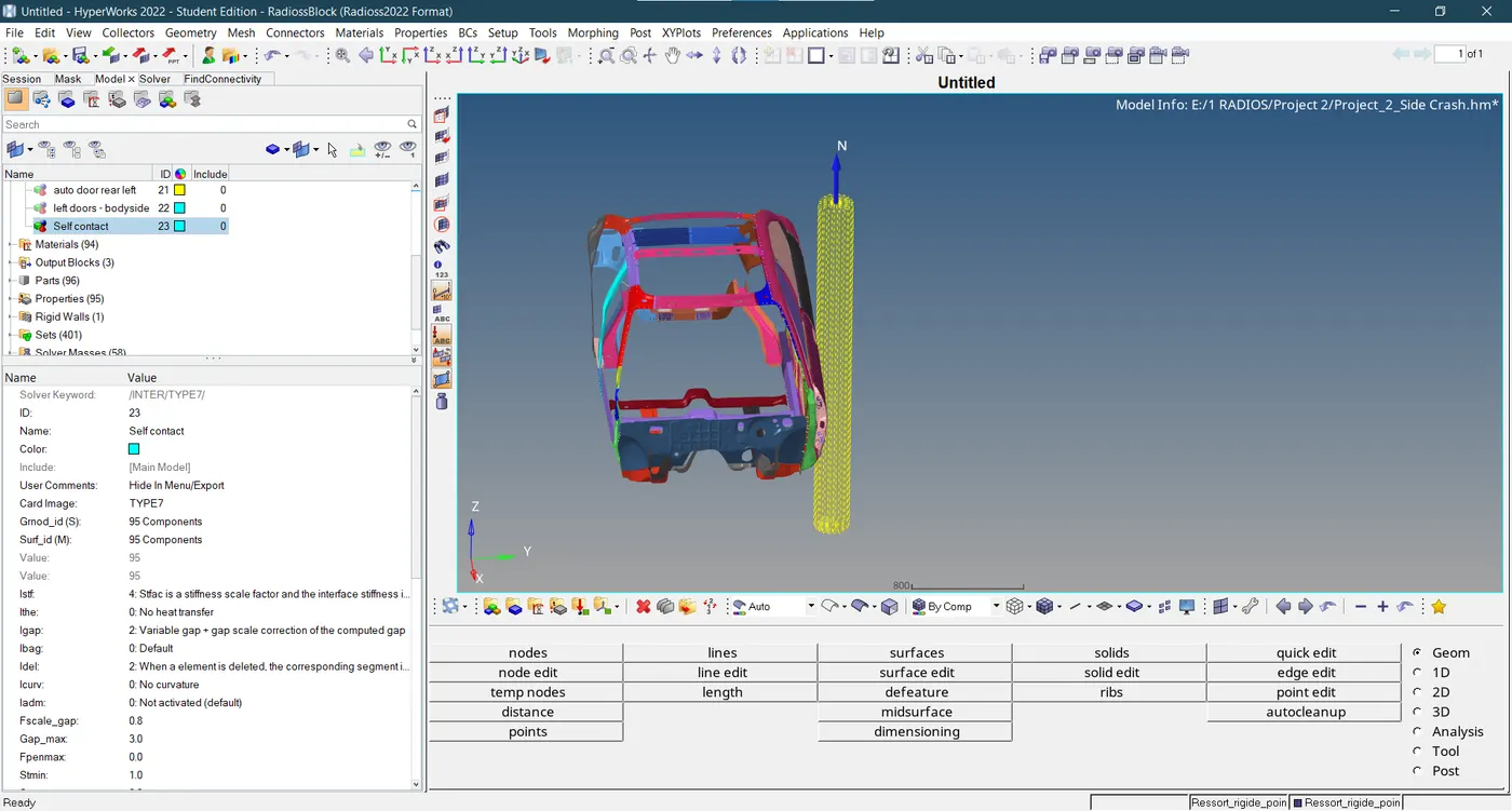
- A collection of nodes and a primary surface can experience any kind of impact thanks to Interface TYPE7, a general-purpose interface. Interface TYPE7 is non-oriented, and secondary nodes may be a part of the main surface, in contrast to interfaces TYPE3 and TYPE5. As a result, this interface can mimic self-impact, particularly buckling in a fast-moving collision.
- Interface TYPE7 addresses every issue and restriction that arises with interfaces TYPE3 and TYPE5. Since a direct search method is used to find the closest section, there are no search restrictions and all potential contacts are located. A cylindrical gap is used around the edges to eliminate the energy jumps caused by a node colliding from the shell's edges.
- Last but not least, interface TYPE 7's primary benefit is that its stiffness varies with penetration, preventing the node from passing through the shell's mid-surface. Many poor contact treatments are resolved by doing this (common when utilizing either interface TYPE3 or TYPE5).
- Use the Penetration Check tool to look for element penetrations and intersections in components or groups. You can use intersection and penetration separately or together. Intersection is the definition of elements flowing entirely through one another, whereas penetration is the overlap of the material thickness of shell elements. Node to Segment and Edge to Edge penetrations are the two main categories under which penetrations fall. The majority of commercial Finite Element solvers have either an Edge to Edge or Node to Segment interface, or most frequently, a combination of both.
- When a secondary node is situated within the thickness of a major segment, a node-to-segment penetration occurs. Solvers typically refer to these penetrations as "node to surface" penetrations. A secondary node is a sphere that is numerically equal to the greatest thickness of all the secondary segments it is attached to during penetration checks.
- Edge-to-edge penetrations are the result of two separate virtual edge cylinders of segments interfering with one another—they do not share a common node.
- Self-penetrations due to the incredibly thick sections. Large segment thicknesses (relative to segment edge lengths) can be seen in some interface segments. You may find penetrations within the same component, depending on the type of penetration check that was done.
- When an element's edge meets the mid surfaces or faces of another shell element or solid element, respectively, an intersection is created. Because intersection checks are independent of solver parameters, they are independent of user profile.
Most solvers do not report intersections. However, they should be avoided at all costs as their existence will cause serious problems during analyses.
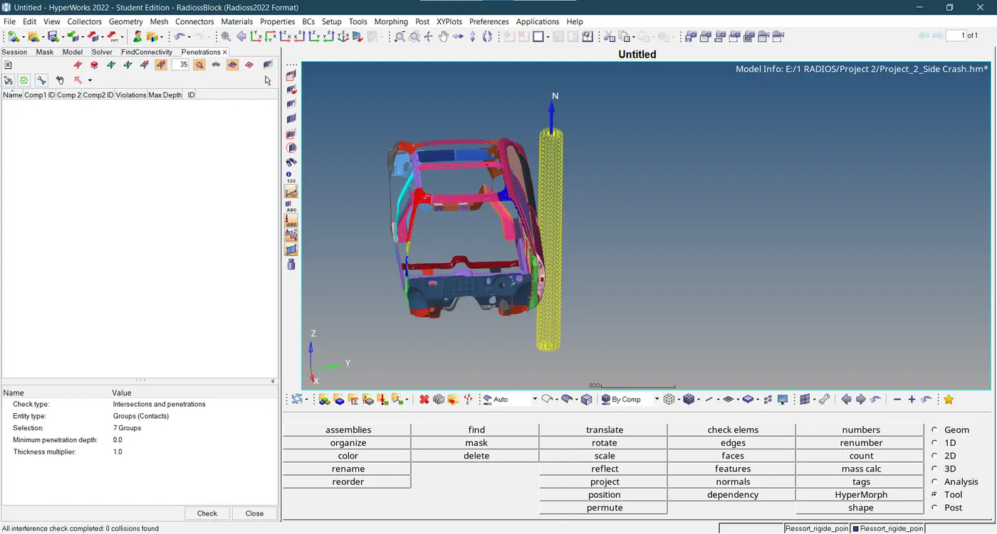
- When performing compliance testing to meet the criteria of S9 of FMVSS No. 214, "Vehicle to pole requirements," this laboratory process must be adhered to. Each vehicle must be evaluated by crashing it at any speed up to and including 32 km/h (20 mph) onto a fixed, rigid pole with a diameter of 254 mm (10 inches).
For passenger cars, multipurpose passenger vehicles, trucks, and buses with a gross vehicle weight rating (GVWR) of 4,536 kg (10,000 lb) or less, these requirements are applicable. However, they do not apply to walk-in vans, motor homes, tow trucks, dump trucks, ambulances, or other emergency rescue/medical vehicles (including those with firefighting apparatus), wheelchair lift-equipped vehicles, vehicles with raised or altered roofs, or vehicles without doors.
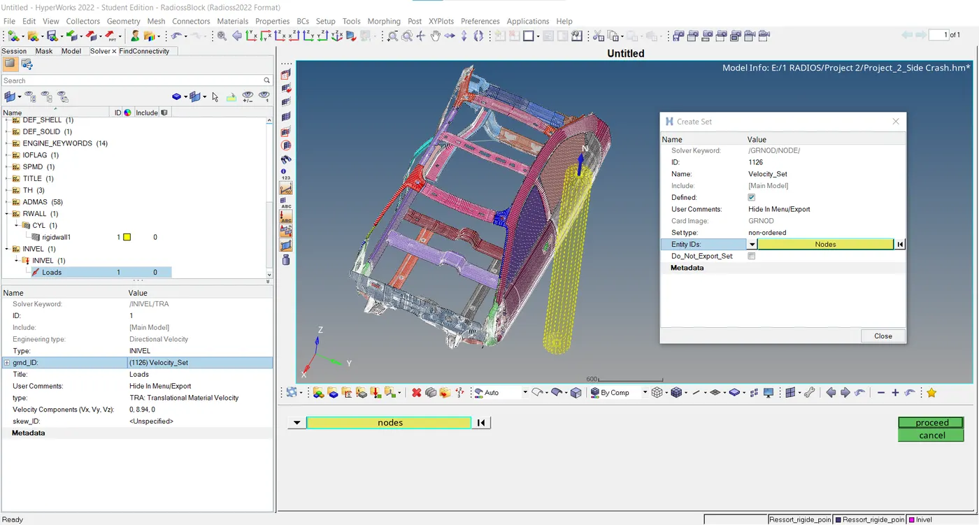
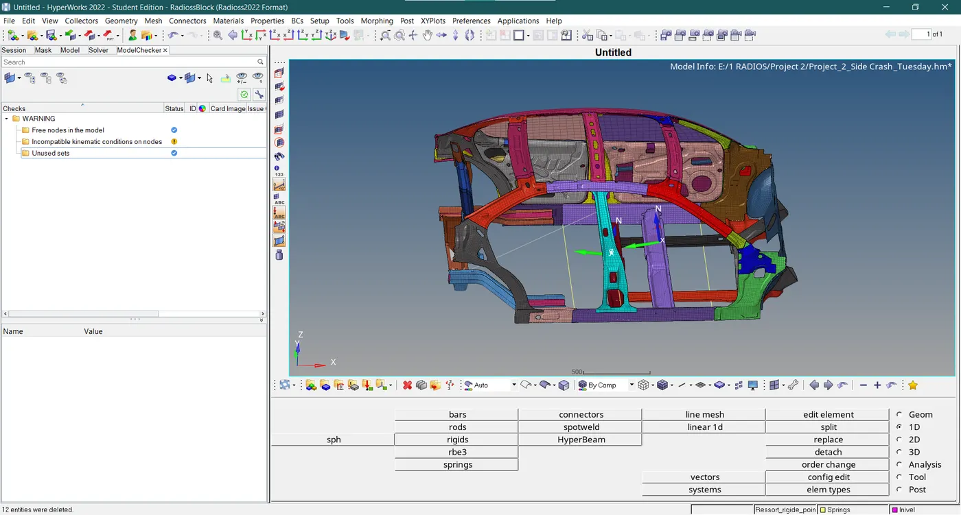
- The model checker is used to check and eliminate any errors and cautious warnings in the model.
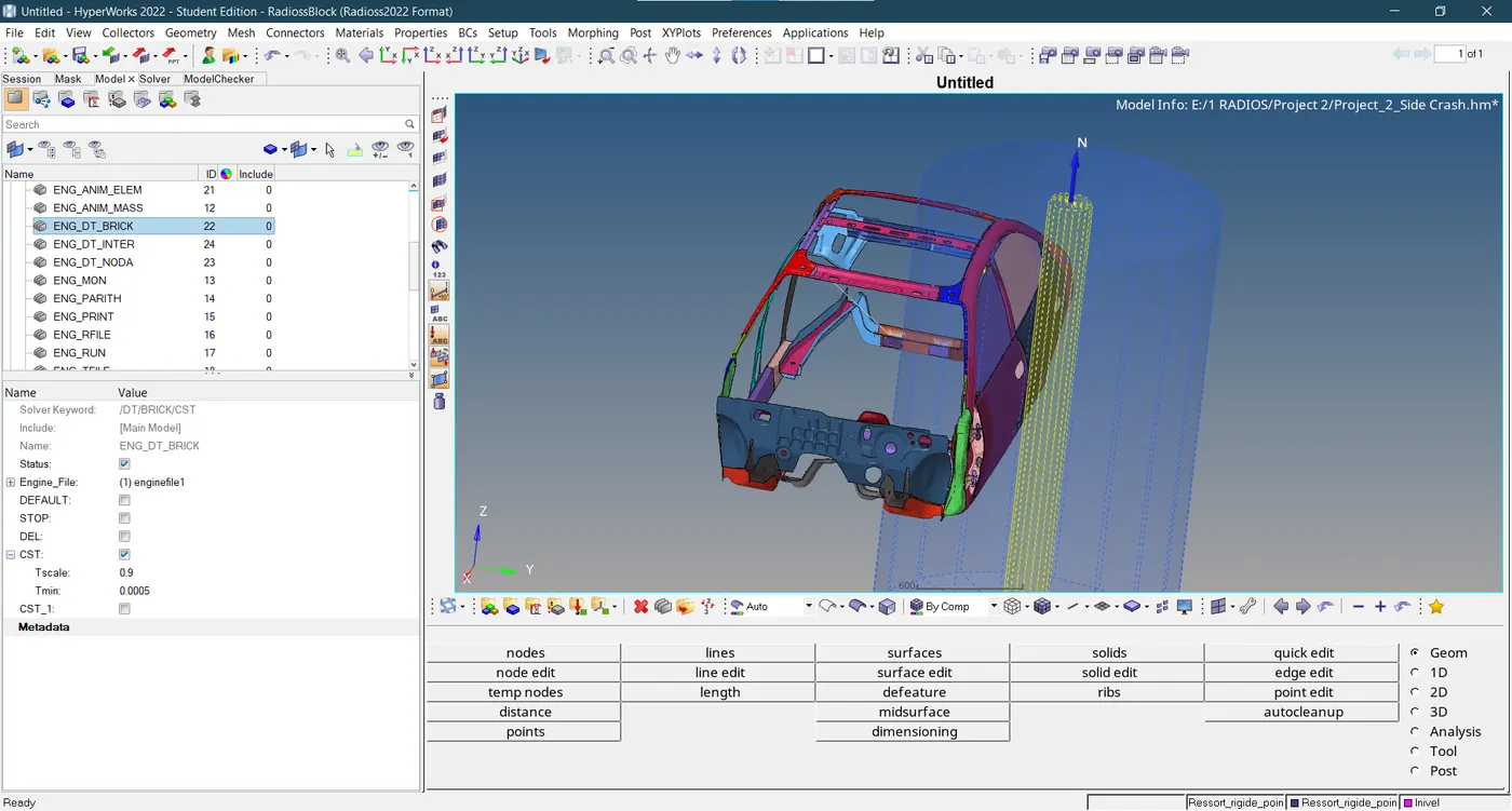
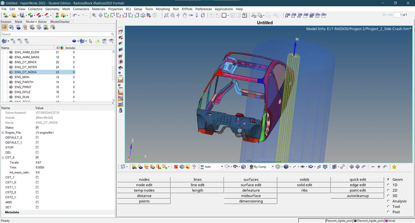
- The minimum time step size is assigned to solid and shell elements of the car model in Engine DT cards.
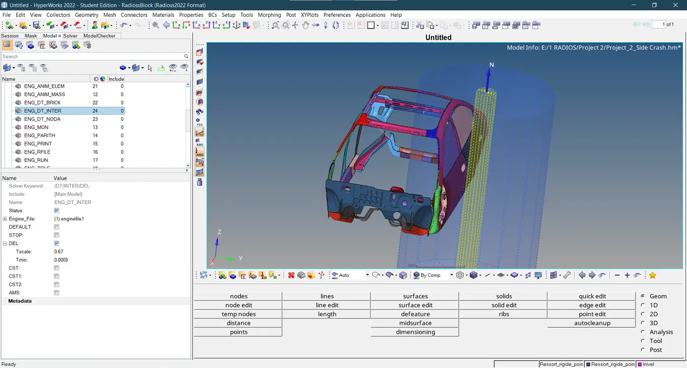
- DT Inter is interface/contact time step size engine card adjusted as shown below.
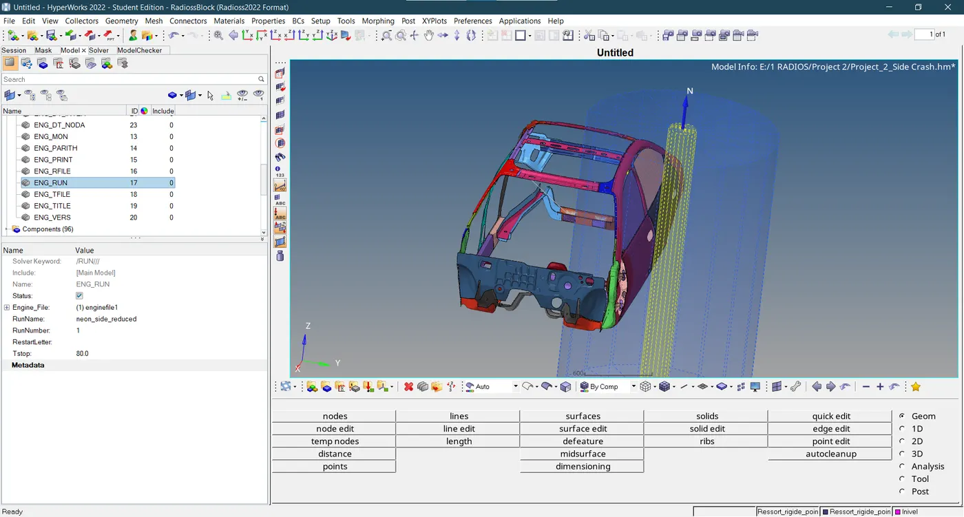
- A termination time of 80 ms is allocated to the ENG_RUN card for this side pole crash analysis.
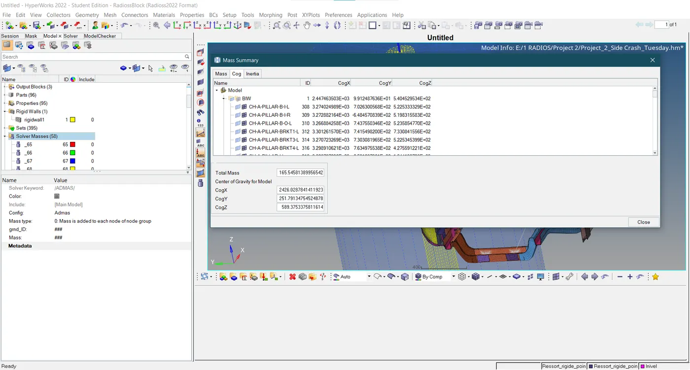
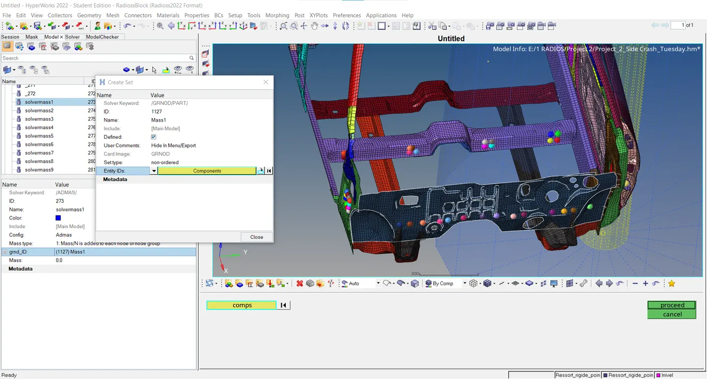
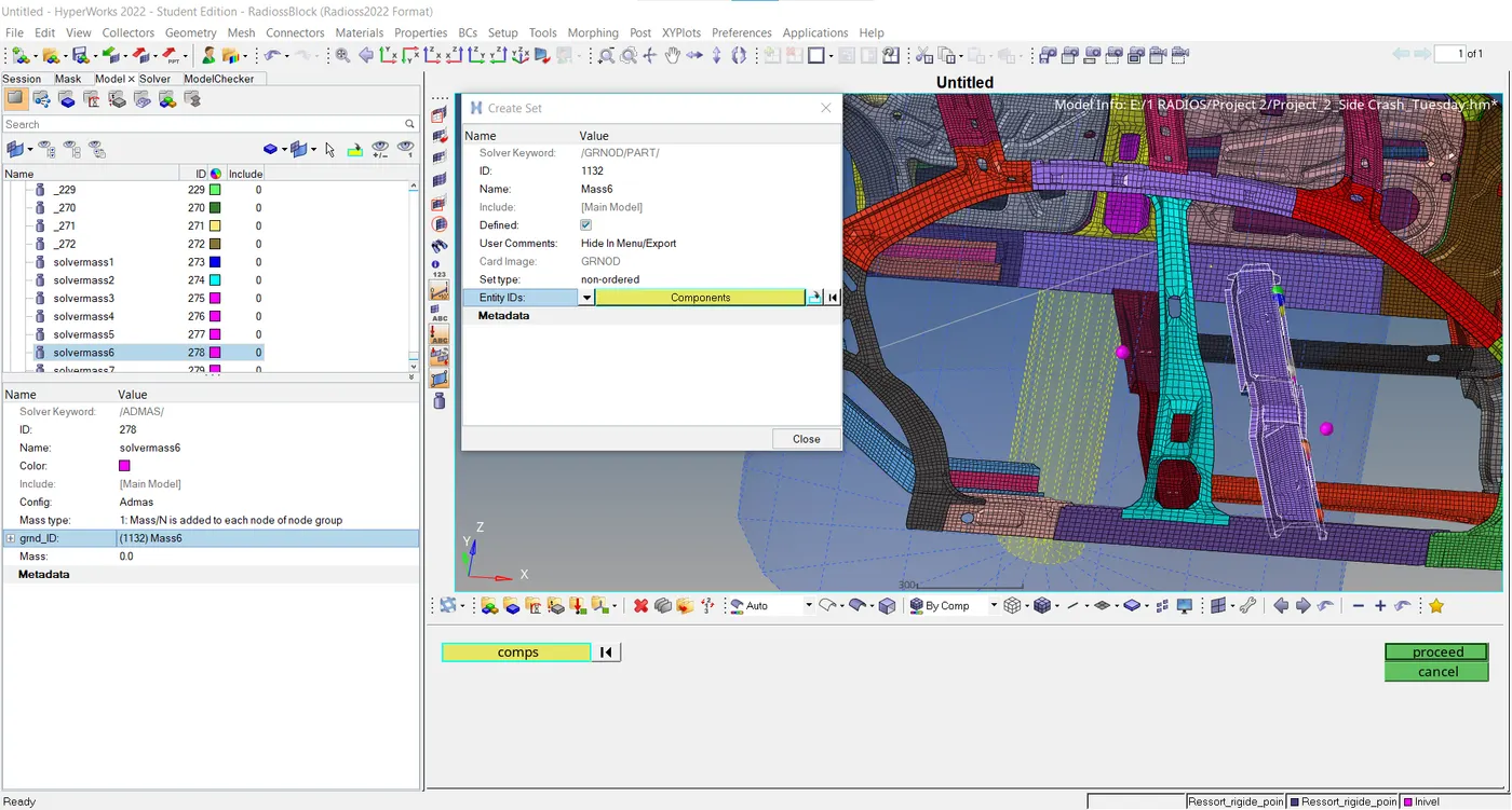
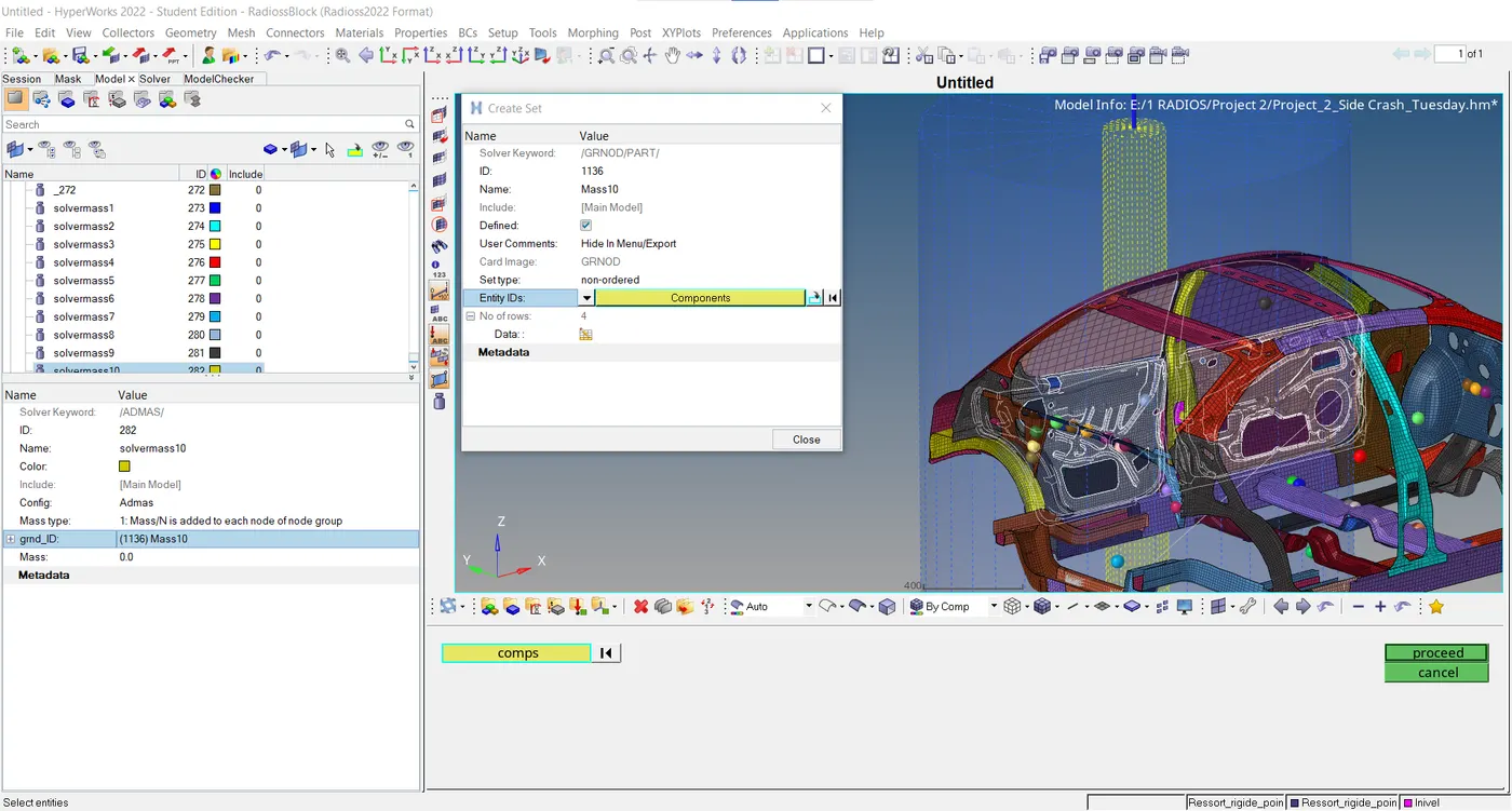
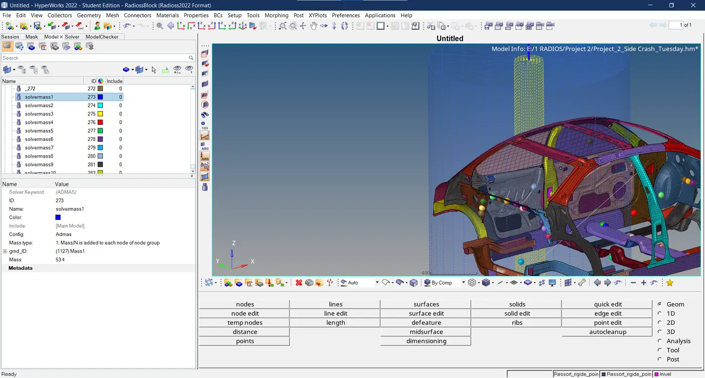
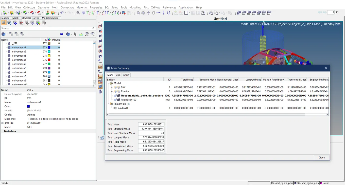
- A lumped non-physical mass of 700 Kg is distributed along the C.O.G of the car evenly and uniformly. By creating different sets of elements the mass is equally attributed to the components surrounding the C.O.G of the given model.
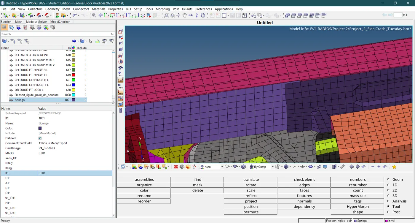
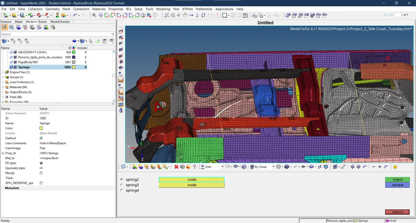
- The springs are created in three areas to acquire the output incursions post-analysis.
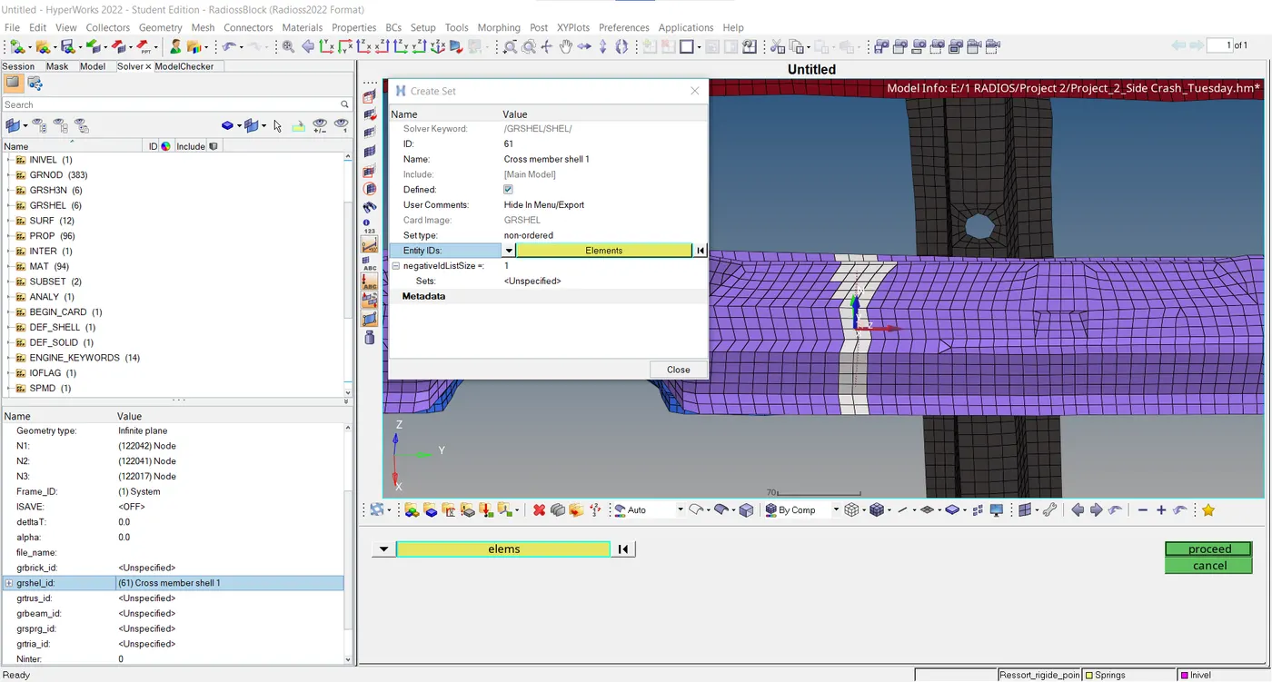
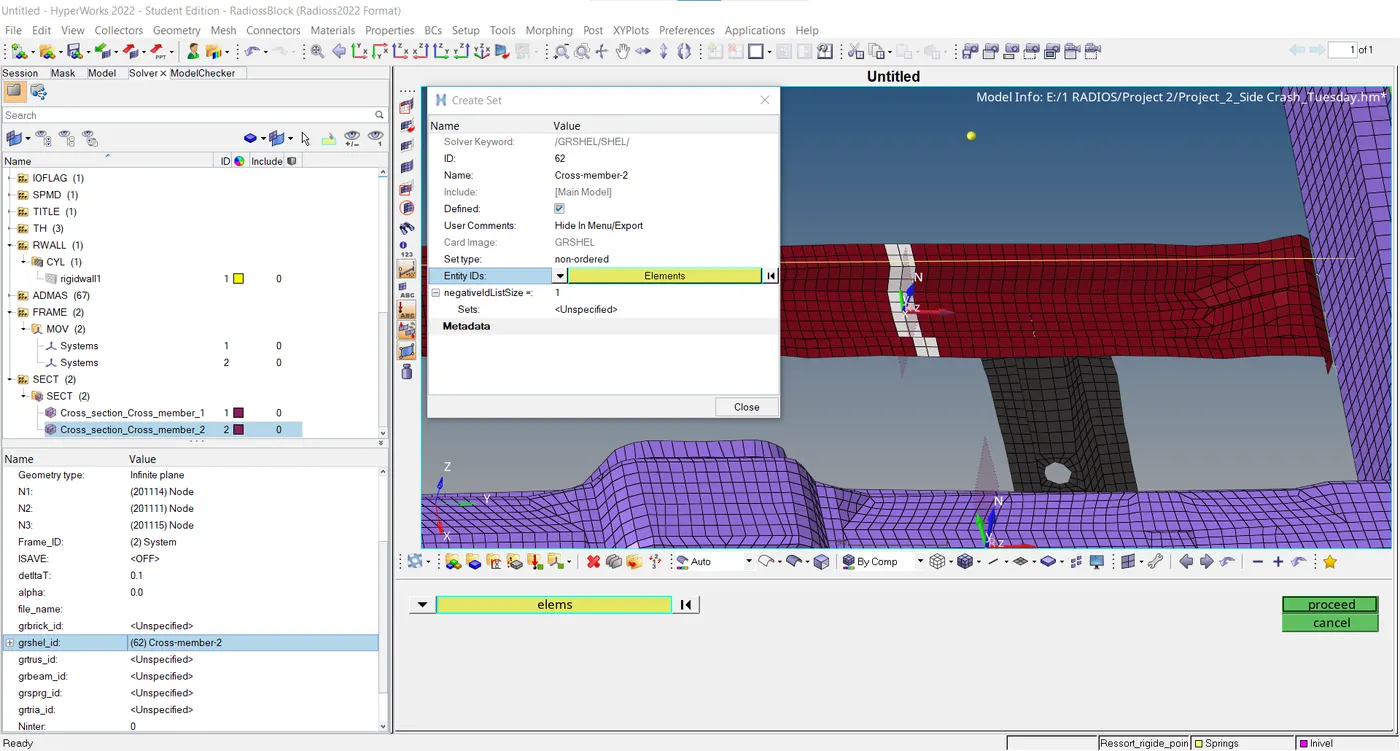
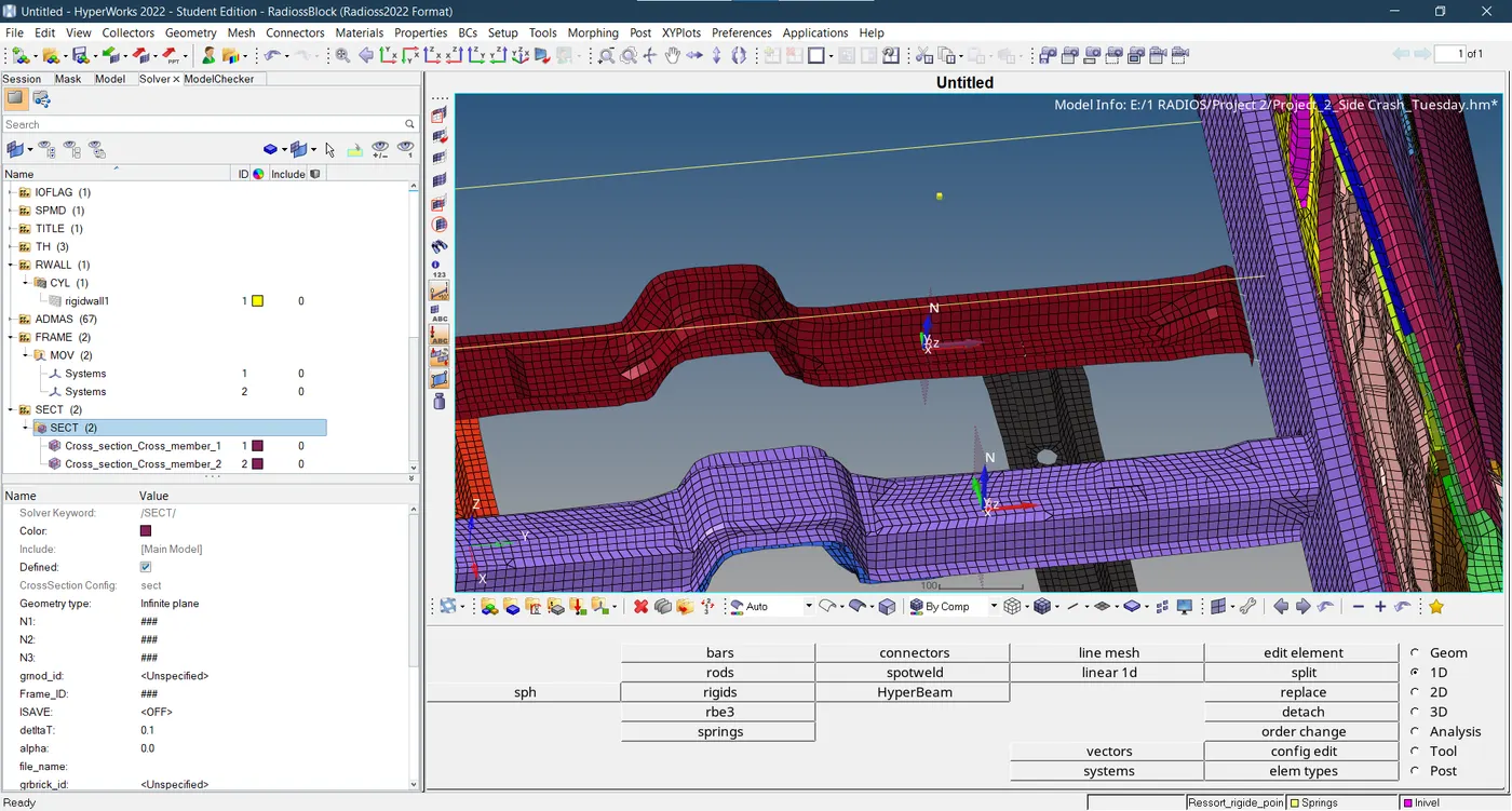
- The moving frames and cross sections are developed for cross members of the model to obtain sectional forces.
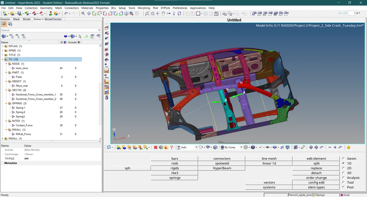
- The TH plot is created that describes the time history output for appropriate blocks.
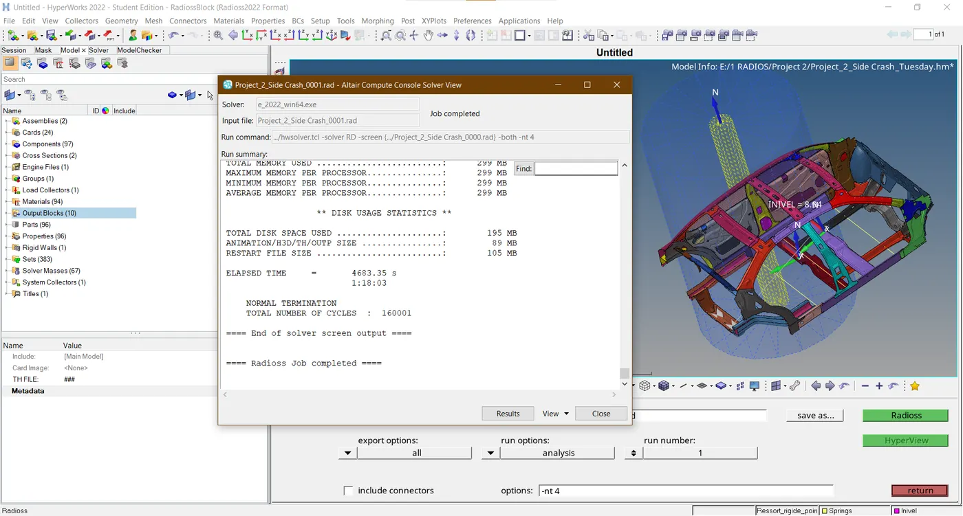
- Eventually, after completing pre-processing and solving the analysis is initiated and it takes around 78 minutes to run the solution.
RESULTS
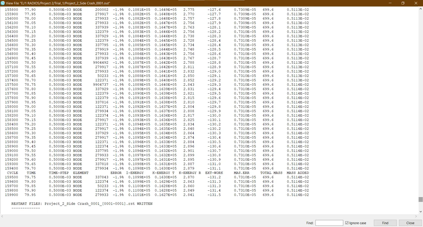
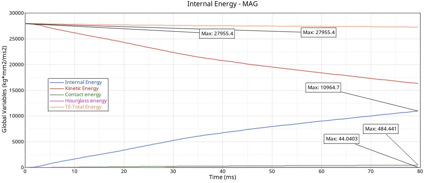
- The mass percentage error and energy percentage error are within acceptable standards for this simulation.
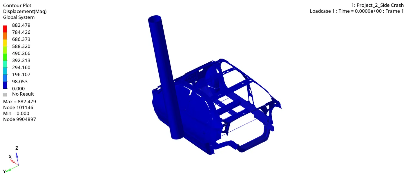
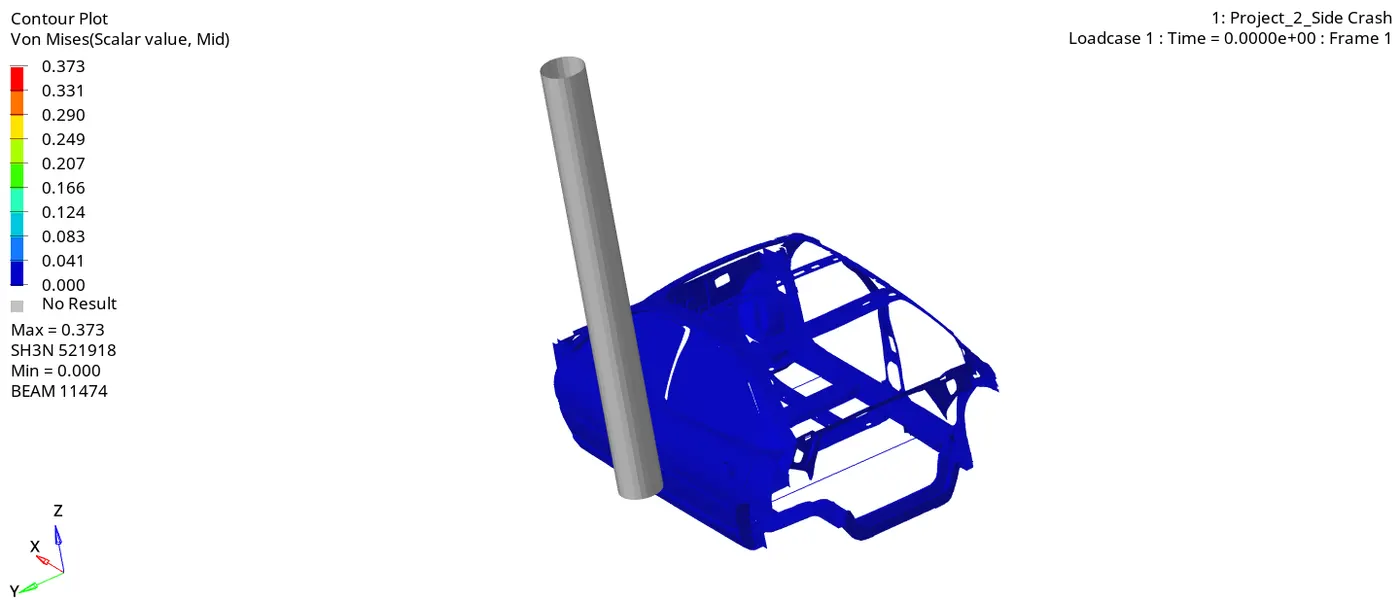
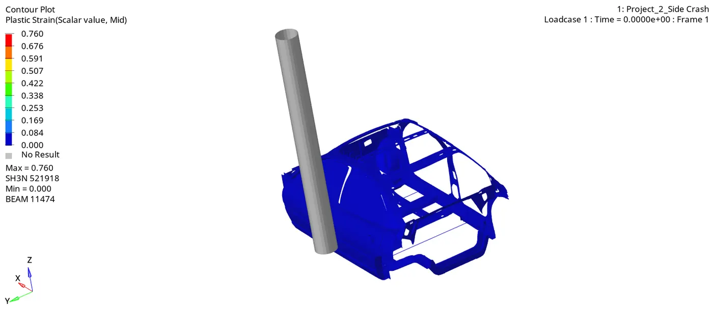
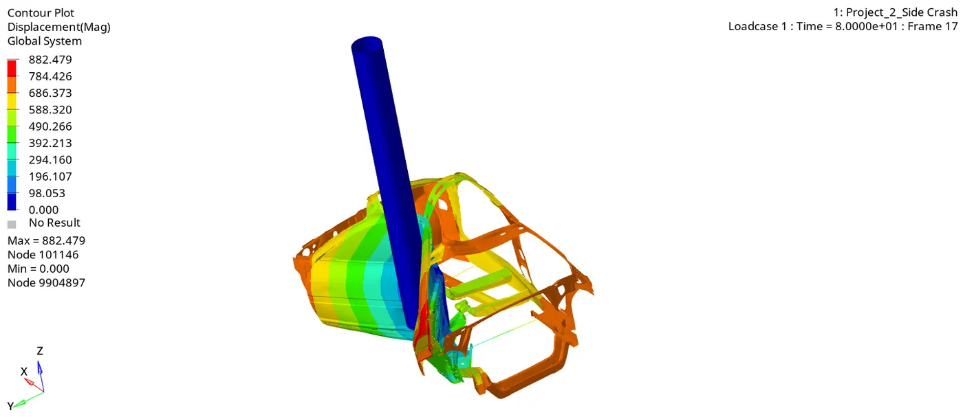
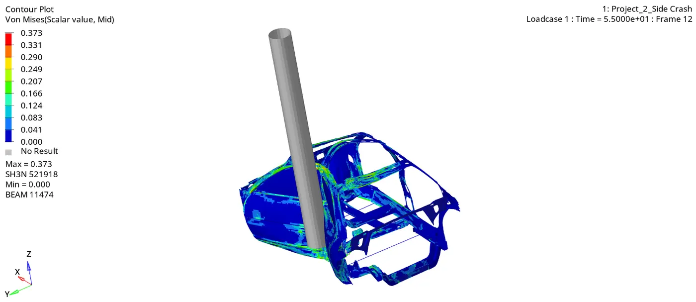
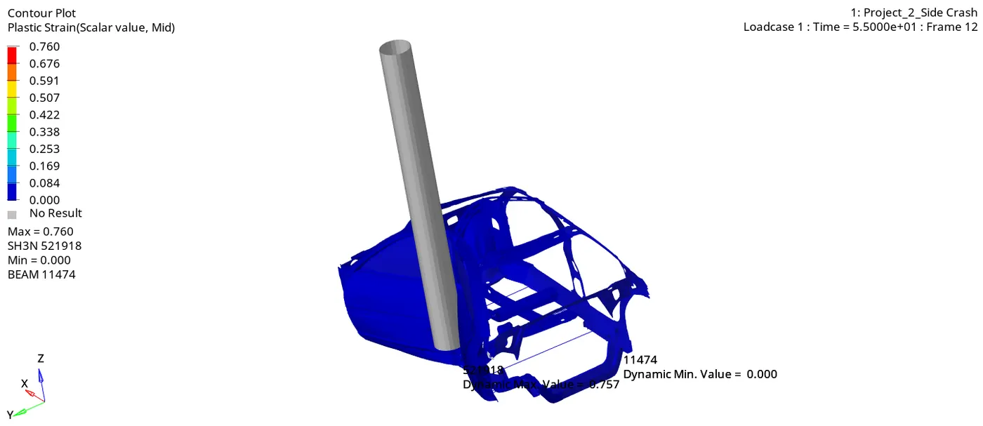
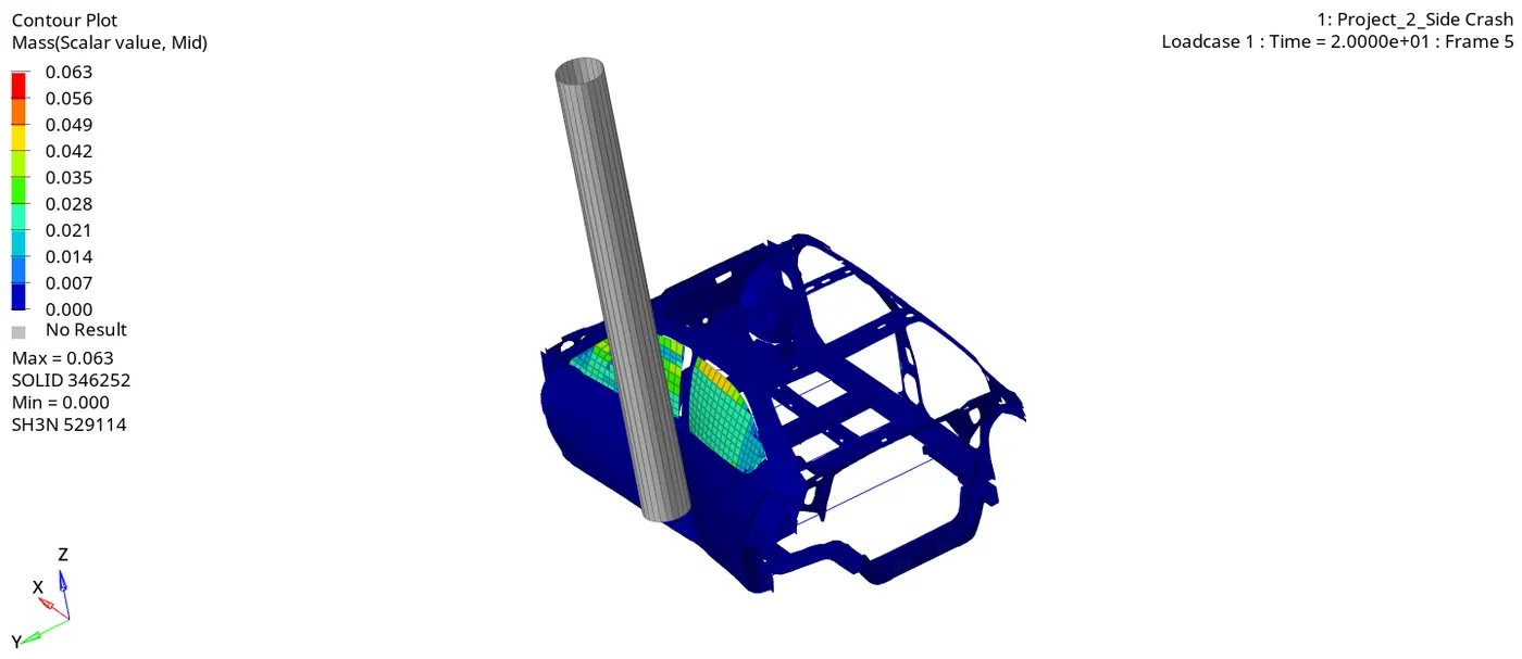
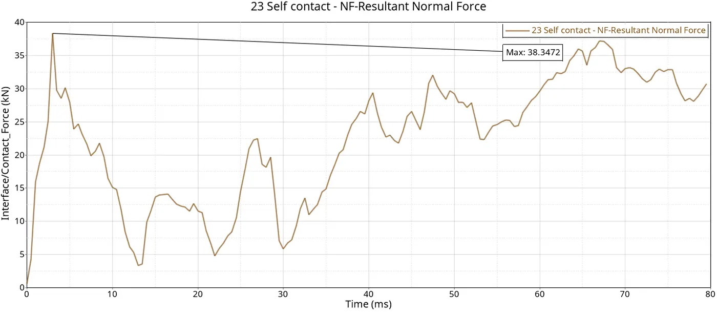
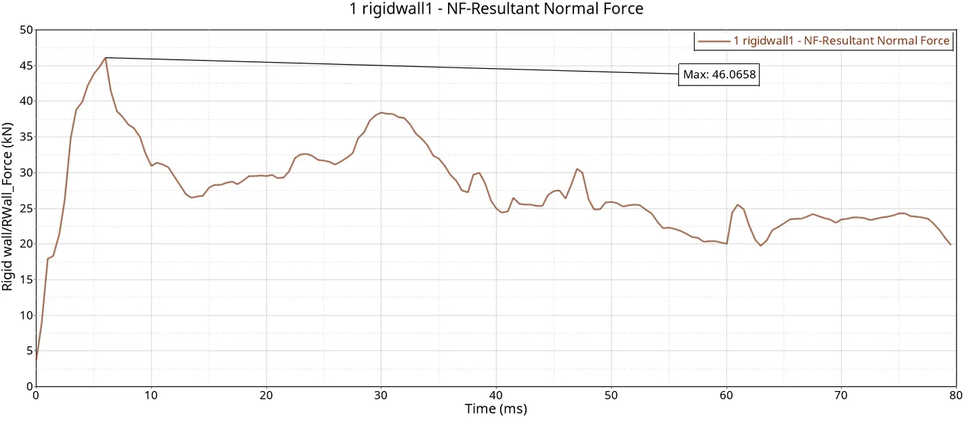
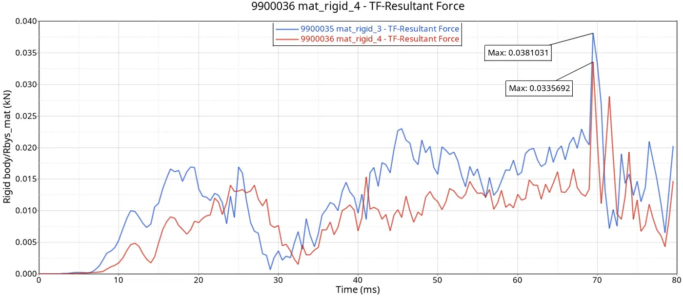
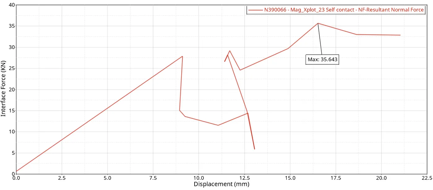
Sectional force in the cross-members
Intrusion at B pillar, hinge pillar and fuel tank region
Peak velocity of an inner node of the door
CONCLUSION
- As the thickness of the B-Pillar increases, so does the maximum impact force between the rigid pole and the B-Pillar. It is clear that when thickness grows, the B-Pillar's mass also increases, producing a strong impact force. However, since using less thickness puts more stress on the B-pillar, this does not imply that a thinner B-pillar is preferable. Therefore, based on the facts above, it can be said that depending on the application, a B-Pillar's thickness might vary, with neither being better than the other. This investigation's primary goal is to choose a lightweight B-Pillar without compromising impact behaviour. When it comes to impact performance, using the average value for the designated thicknesses enhances the TWV's body sections and passengers' performance when compared to other options.
- By dividing the objective lumped mass addition of 700 kg equally across all the parts of the specified chassis model, the target became apparent.
- A slight increase in hourglass energy is observed post-simulation between the rigid pole and components of the car model.
- The kinetic energy and internal energy embark into convergence uniformly during simulation.
- The intrusion in the B-pillar and fuel tank is more contrary to the Hinge pillar. This is due to the fact that the former components are closer to the area of impact.
- The errors weren't observed or examined during trials and testing while pre-processing or solving this type of analysis. It is most probably because the model, boundary conditions and loading conditions were simple for this project.
- To reduce infiltration into fuel tanks use materials with great strength, and reinforce the B and hinge pillars. Use materials that absorb energy to surround the fuel tank. Boost the safety against rollovers. Enhance the protective design of fuel tanks. Install a protective cage encircling the fuel tank. Carry out rigorous simulation and crash testing. Verify adherence to safety guidelines.