Week 1 Spur Gear Challenge
STATIC STRUCTURAL ANALYSIS ON SPUR GEAR
INTRODUCTION
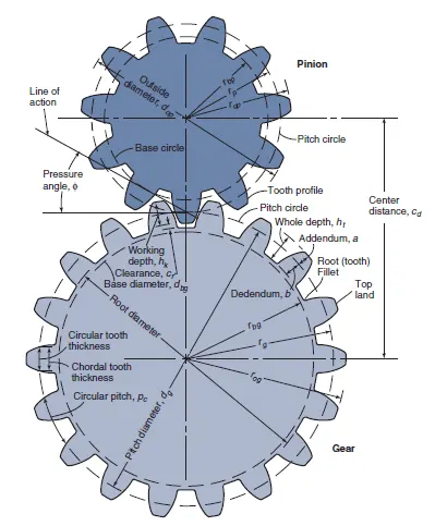
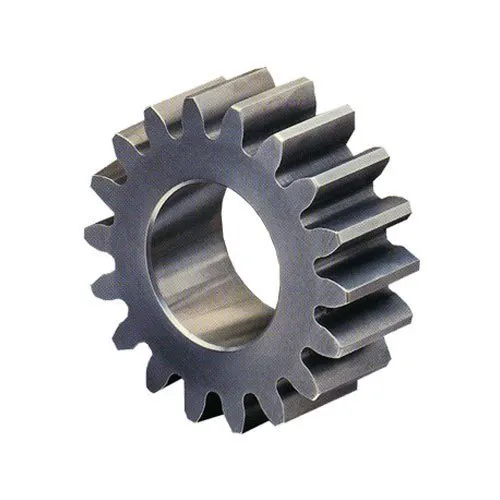
One of the most widely used varieties of precision cylindrical gears is the spur gear. Straight, parallel teeth are arranged around the cylinder body's perimeter, and a central bore that fits over a shaft completes the straightforward construction of these gears. A hub is machined into the gear in several variations, thickening the gear body around the bore without altering the gear face. Another option is to broach the central bore so that the spur gear can be fitted onto a keyed or splined shaft.
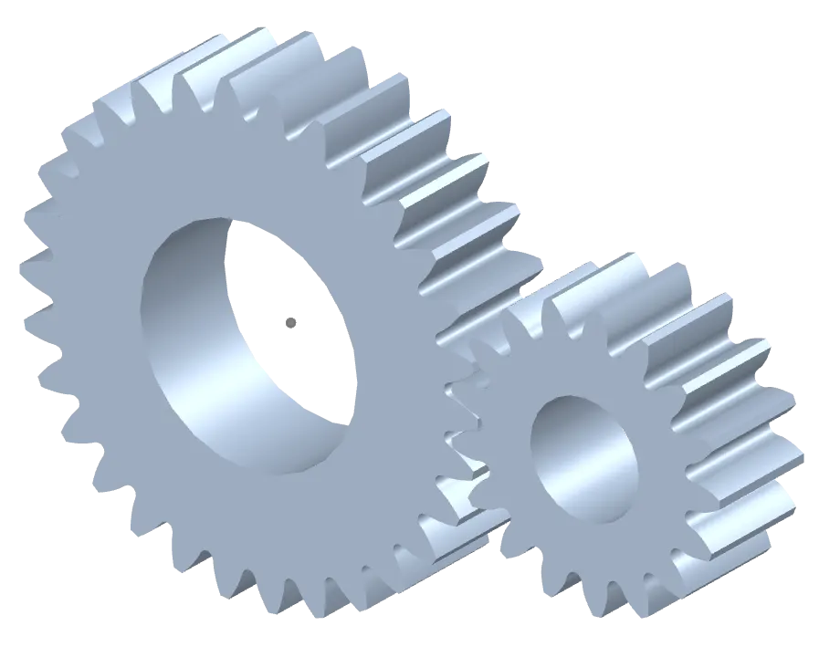
Spur gears transfer motion and power from one shaft to another through a series of matched gears, and are used in mechanical applications to multiply torque or change a device's speed.
The performance of a spur gear is greatly influenced by its construction and design. They must be made of premium materials and to exact measurements for them to perform their duties properly and efficiently. Each feature's dimensional specifications are essential to understanding how a particular gear works. Therefore, to guarantee clarity and accuracy in the manufacturing or purchase order, an industry professional must be conversant with the phrases about each gear part and their corresponding measurements whether they need to create a new spur gear or replace an existing one.
In a mechanical system, spur gears are used to transfer power and motion between shafts. This transference can amplify torque, change the operating speed of machinery, and enable positioning systems to be precisely controlled. Because of their architecture, they can be used in operational conditions that tolerate more noise or at slower speeds.
Typical industrial applications include the following:
- Transmissions
- Conveyor systems
- Speed reducers
- Engines and mechanical transportation systems
- Gear pumps and motors
- Machining tools
Spur gears have several advantages for industrial processes and applications, such as:
Ease of use. Spur gears are easy to design and install, even in confined or limited spaces, thanks to their straightforward, compact design.
Drive with Constant Speed. These gears maintain a steady velocity while precisely increasing or decreasing shaft speed.
Dependability. Spur gears are not likely to slip when in use, in contrast to other parts of the power and motion transmission system. Furthermore, their resilience lowers the possibility of an early failure.
Economy of Cost. Even with extremely precise or bespoke dimensions, they are less expensive to manufacture and buy because of their design's simplicity, which also increases manufacturability.
Effectiveness. Spur gear systems can transfer significant amounts of power across numerous gears with low power loss, and they have power transmission efficiencies ranging from 95% to 99%.
OBJECTIVES
CASE 1
- Using Cast Iron(ductile) as a material, carry out a static structural analysis to find out Equivalent stress, Total deformation and Stress intensity(Learn about what stress intensity is). Find the location for a possible fracture.
CASE 2
- Using Cast Steel as material, perform the same analysis for the results as in Case 1.
CASE 3
- Using Cast Bronze as material, perform the same analysis for the results as in Case 1.
- Write a detailed report comparing the results of the three cases and conclude which material would you recommend based on these results.
PROCEDURE
CASE 1
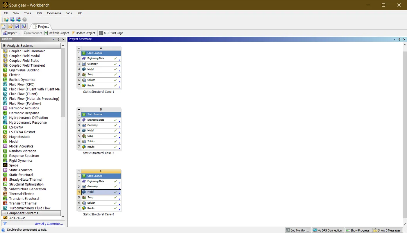
- In this model, the geometry of spur gears is given so the static structural analysis is employed using three different materials.
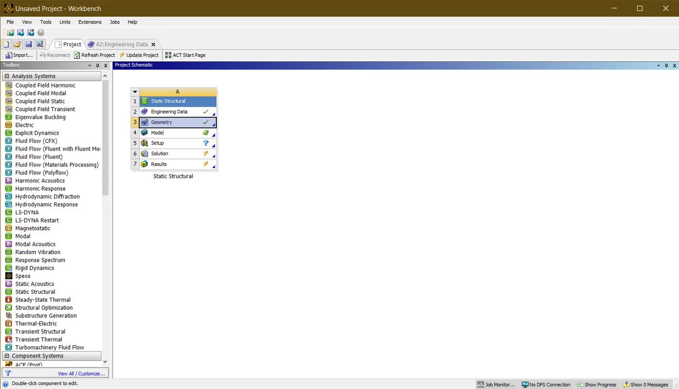
- In Case 1 Ductile Cast iron is assigned to the model with the given standard unit system as displayed below. Ductile iron, also called spheroidal or nodular iron, is really a class of irons that, because of their particular microstructure, have great strength, flexibility, durability, and elasticity. Over 3% of carbon is typically present in cast ductile iron, which may be bent, twisted, or deformed without breaking.
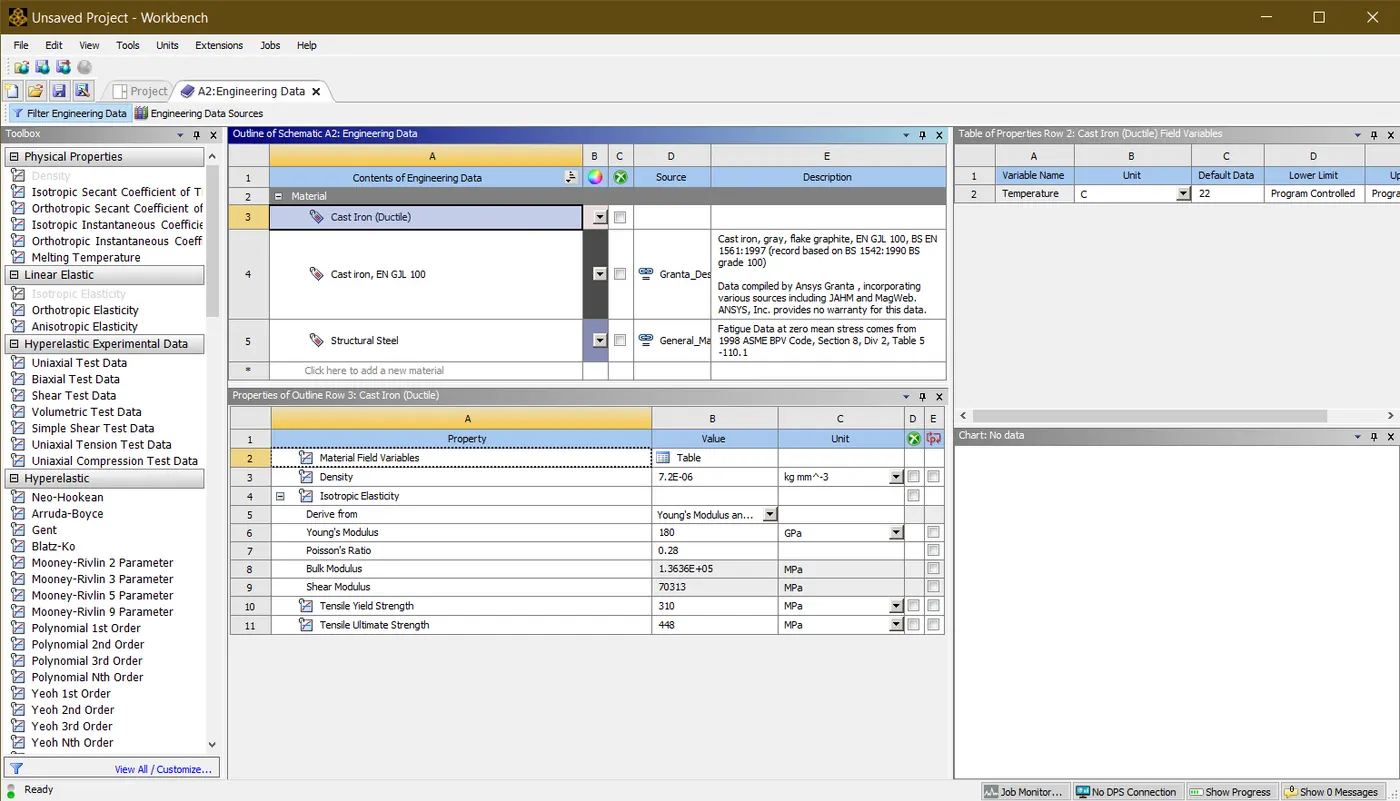
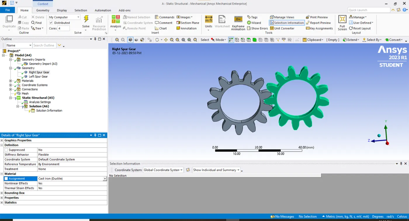
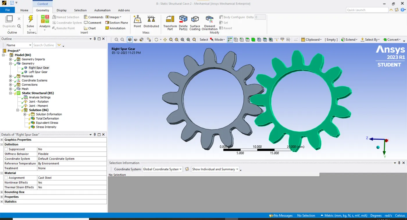
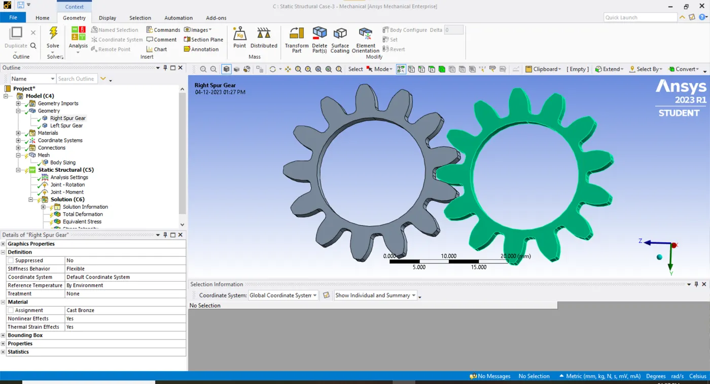
- Since the Geometry item and Engineering data is inputted we embark towards Pre-processing in ANSYS Mechanical. The ductile cast iron is designated to both spur gears as portrayed below.
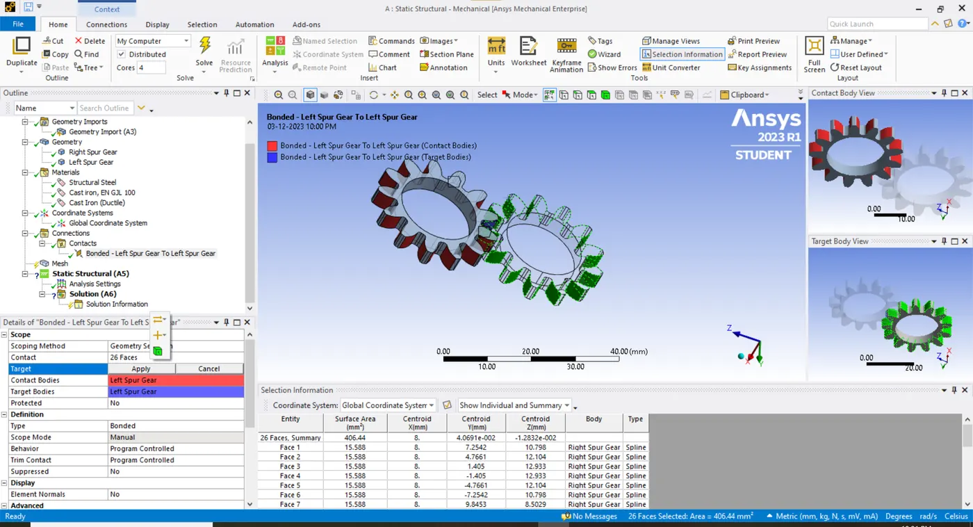
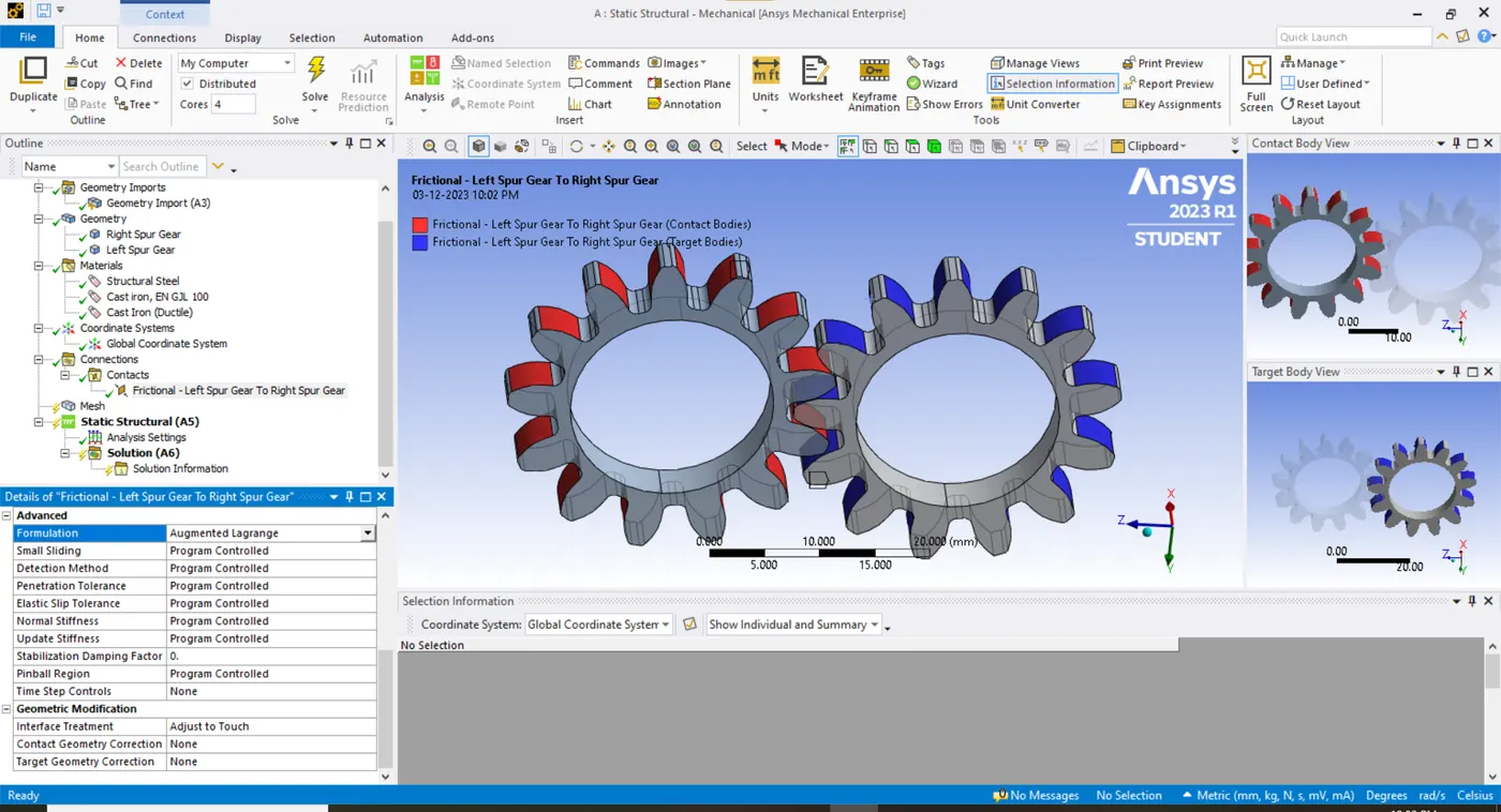
- A frictional contact is set between the spur gears with the given contact formulation and interface treatment. Frictional contact in Ansys Workbench permits a contact pair to move and split apart on a target surface. Tangential movements are impacted by friction coefficients.
- A revolute joint restricts all three relative translations and the other two relative rotations and permits only one relative rotation between two entities. It is frequently used to represent assemblies with linkages that act like pendulums, such as cylinder-pin assemblies (Hinge).
- Using the body to the ground means the body is fixed and will rotate only on its axis. The fixed support is excluded further in boundary conditions while using this option.
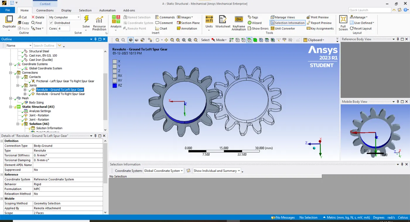
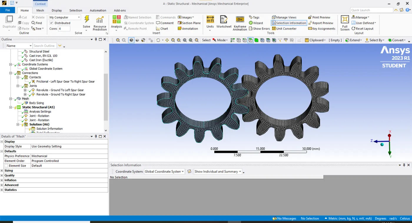
- The refined mesh with the appropriate size is provided for the gears to achieve efficient results.
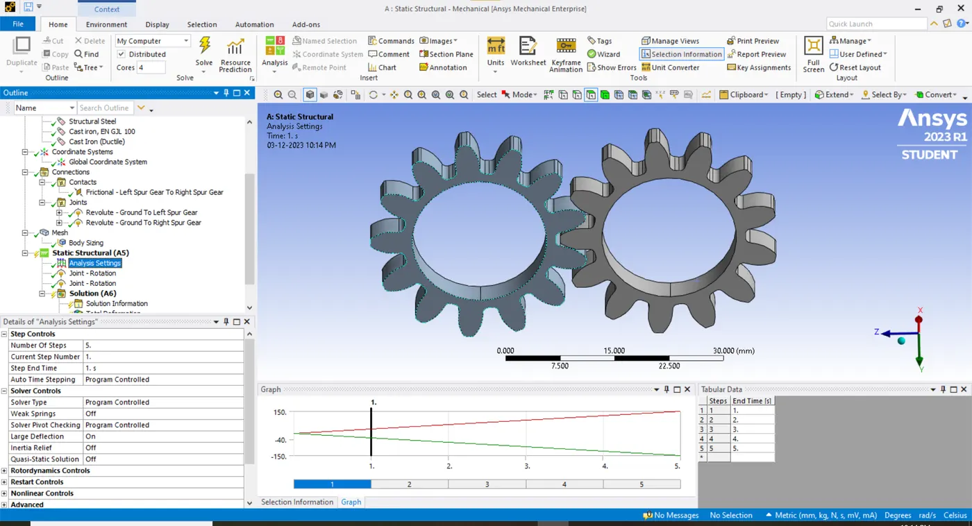
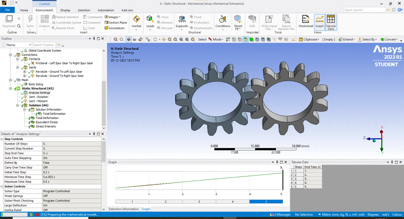
- In analysis settings, the large deflection is turned on to achieve non-linear results. Also, the solution is divided into 5 load steps to acquire detailed results at each instant of the whole process.
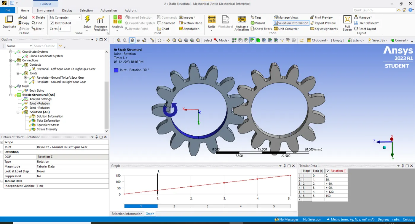
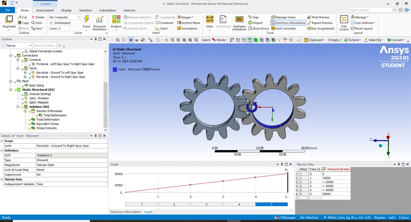
- In loading conditions for the left gear on the revolute joint, a rotational displacement is provided while for the right gear, an angular moment is allocated with given values.
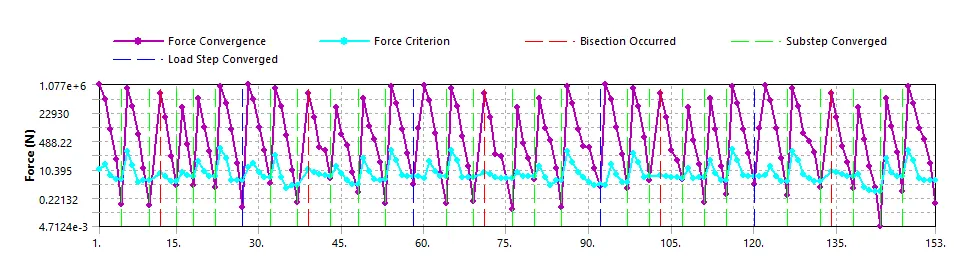
- The initial, minimum and maximum time steps are manually inputted so that load steps are converged with ease.
CASE 2
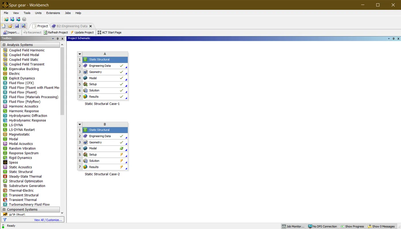
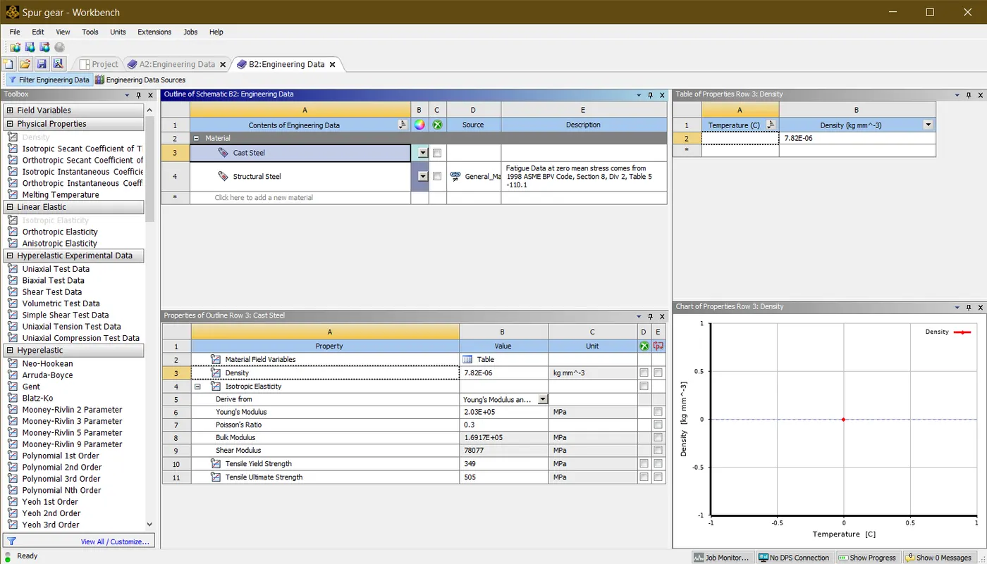
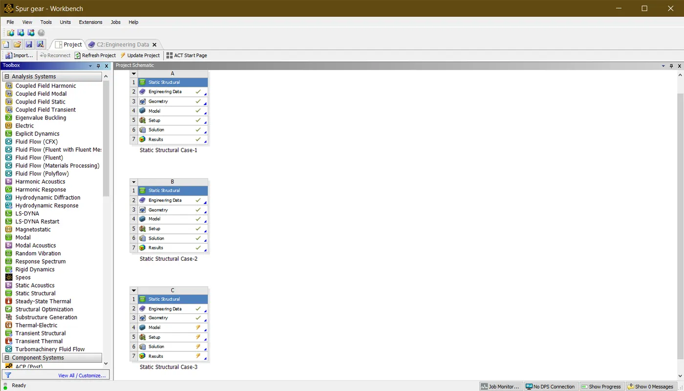
- In Case 2 the duplicate Static structural system is formed from Case 1. The material as given below is changed only the rest of all stages are similar as in Case 1.
CASE 3
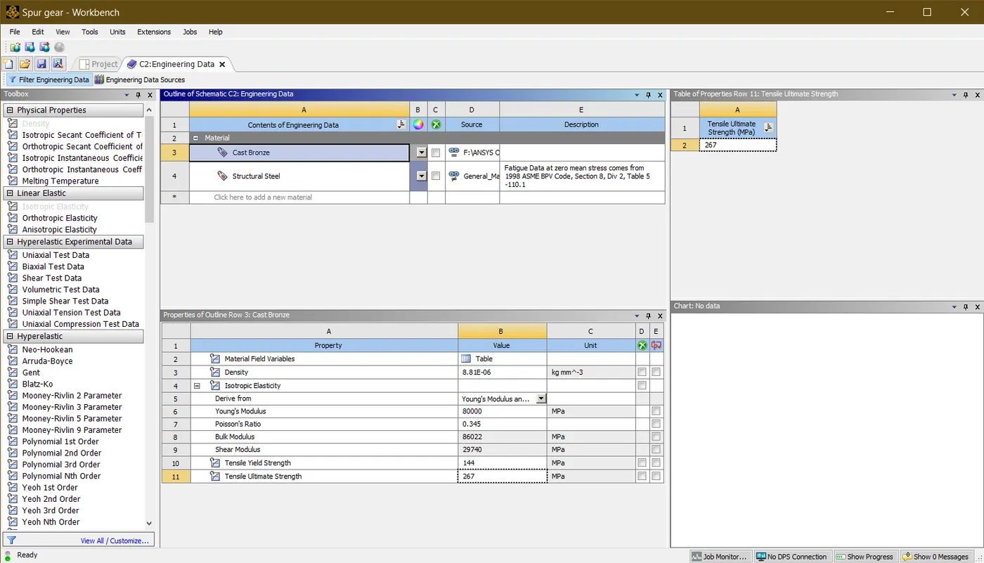
- In Case 3 the duplicate Static structural system is formed from Case 2. The material as given below is changed only the rest of all stages are similar as in Case 1 & 2.
RESULTS
CASE 1
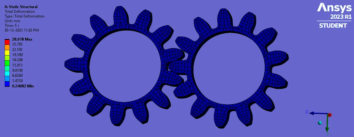
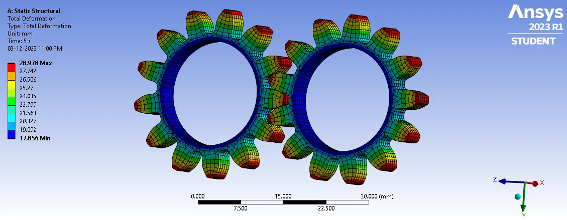
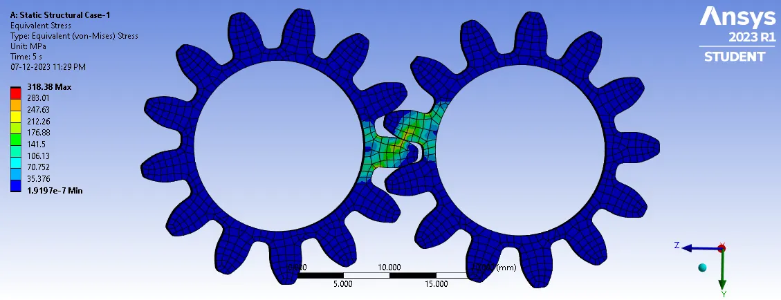
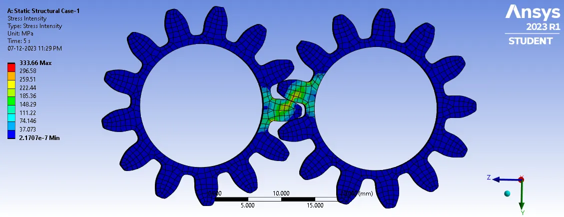
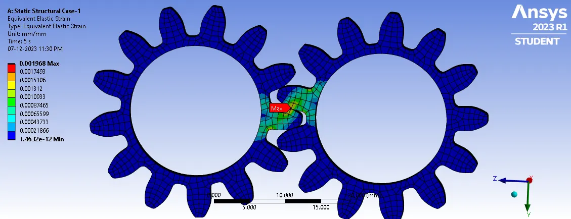
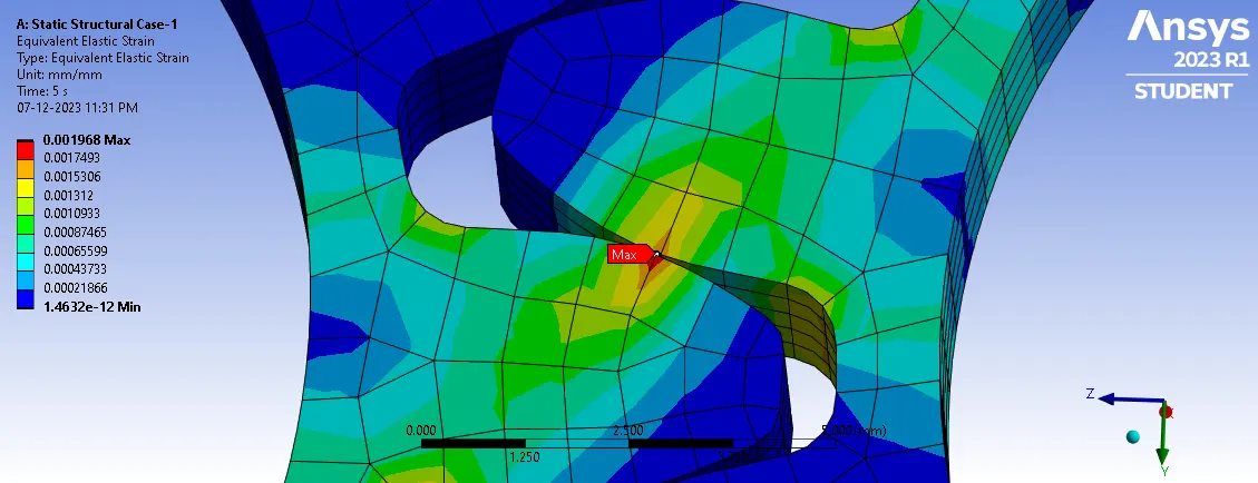
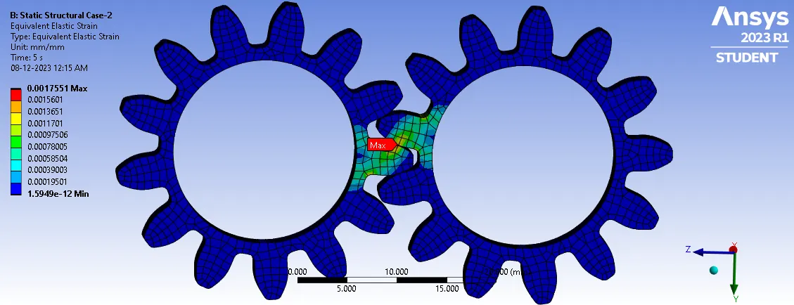
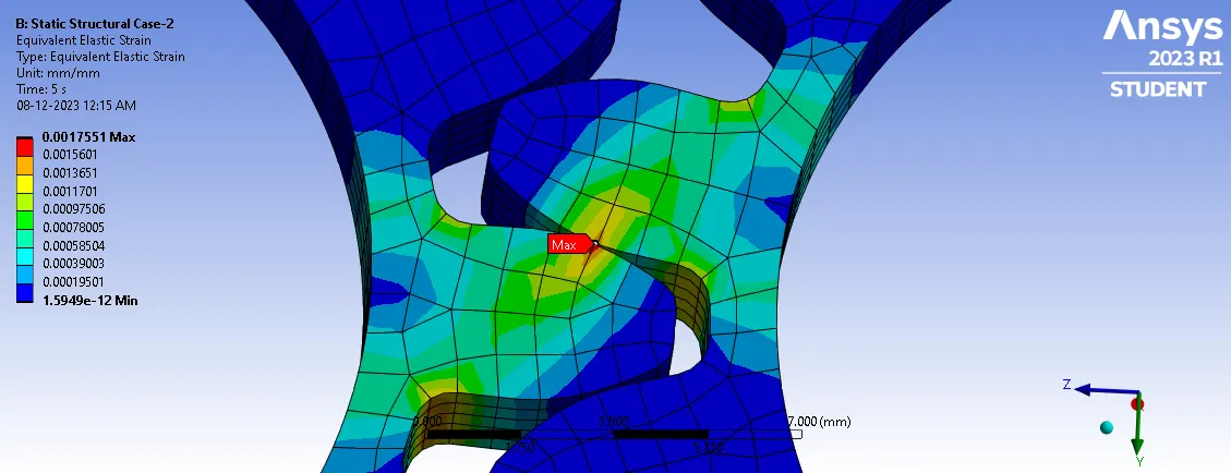
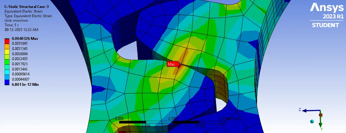
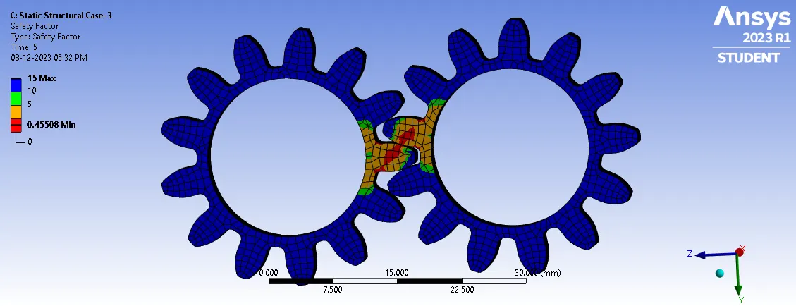
- The maximum strain displayed in the picture below is the common fracture point while both consecutive gear teeth come into contact with constant moment.
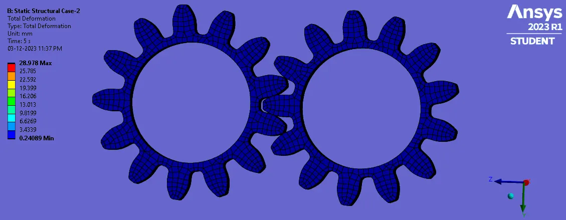
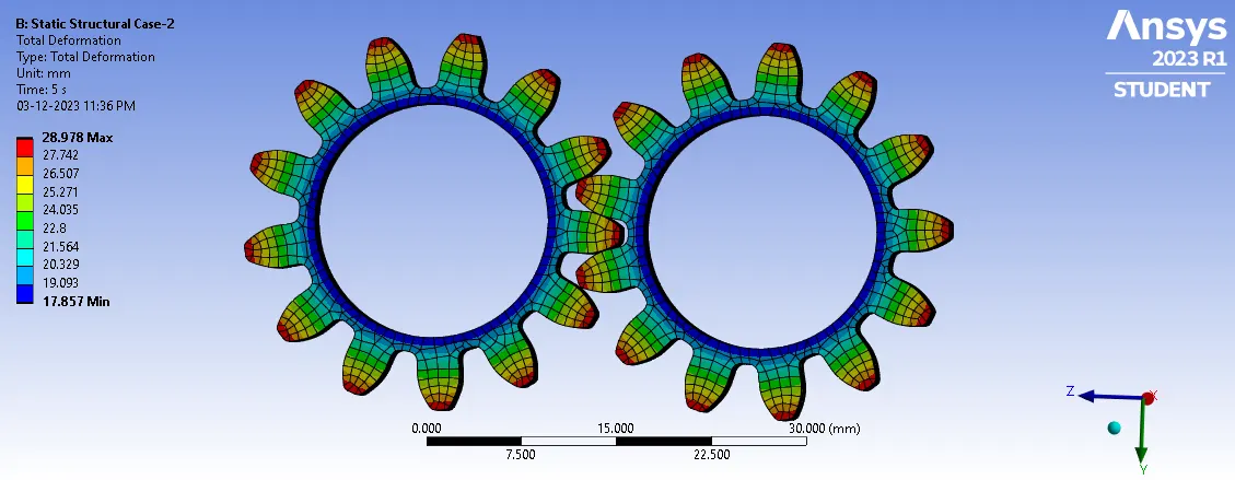
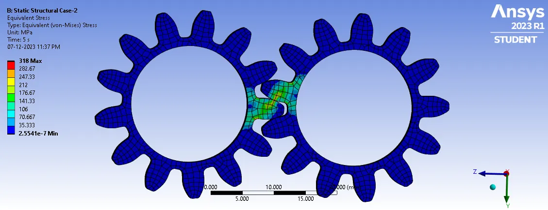
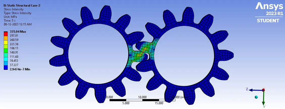
CASE 2
CASE 3
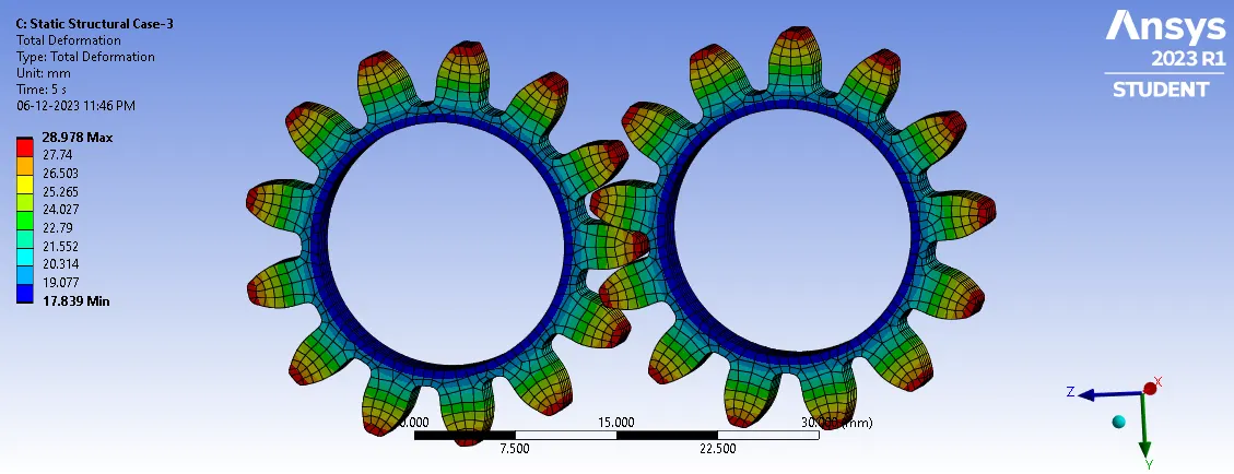
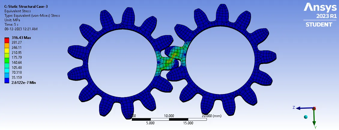
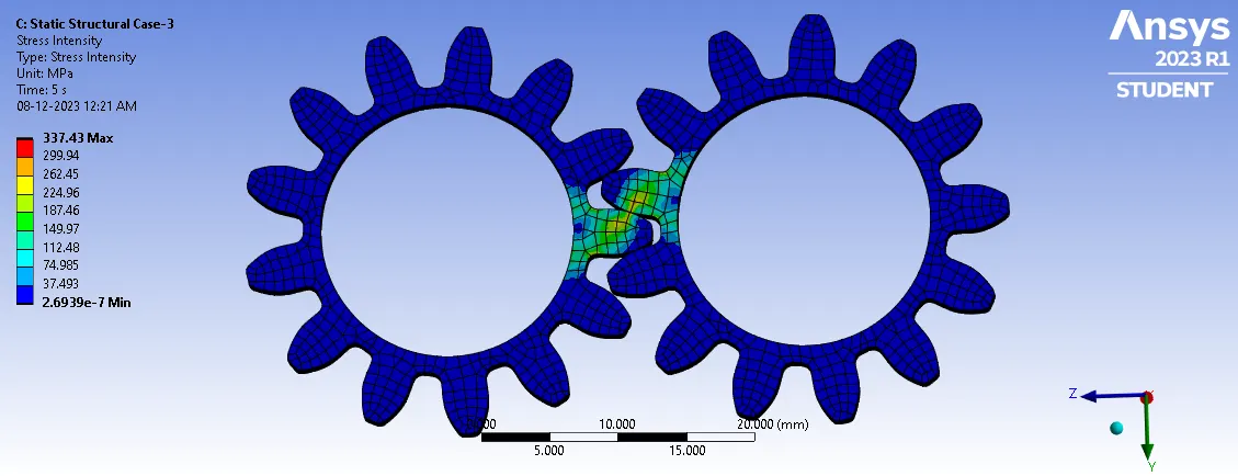
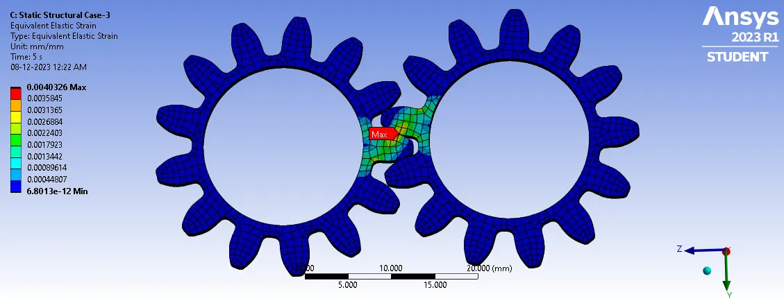
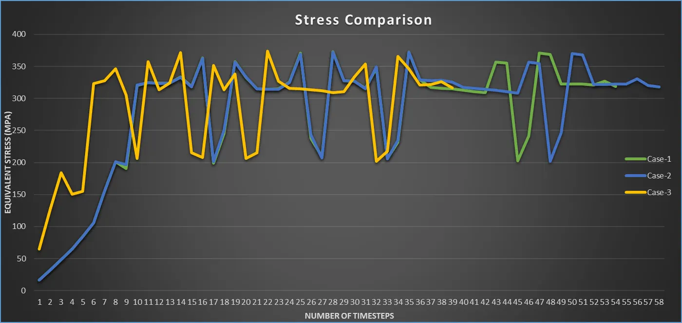
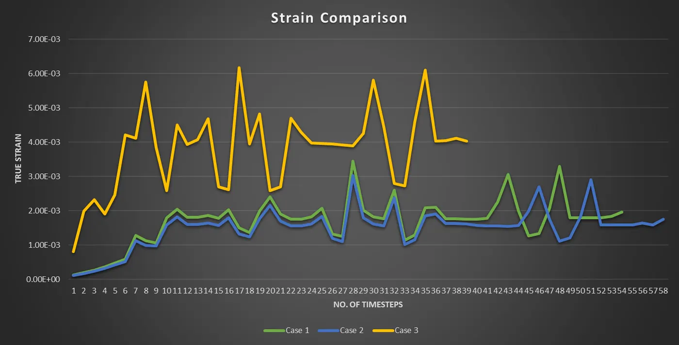
- The comparison of all cases is designated in the form of maximum Stresses obtained in 5 load steps as follows:
| Eq. Stress Case 1 (Mpa) | Eq. Stress Case 2 (Mpa) | Eq. Stress Case 3 (Mpa) | True Strain C1 | True Strain C2 | True Strain C3 |
| 16.507 | 16.429 | 64.581 | 1.26E-04 | 1.11E-04 | 8.11E-04 |
| 32.358 | 32.308 | 126.68 | 1.93E-04 | 1.70E-04 | 1.99E-03 |
| 48.467 | 48.393 | 184.1 | 2.70E-04 | 2.39E-04 | 2.32E-03 |
| 64.948 | 64.842 | 150.86 | 3.62E-04 | 3.21E-04 | 1.90E-03 |
| 84.138 | 84.009 | 155.19 | 4.71E-04 | 4.17E-04 | 2.46E-03 |
| 105.76 | 105.6 | 322.98 | 5.92E-04 | 5.24E-04 | 4.21E-03 |
| 155.73 | 155.9 | 327.81 | 1.28E-03 | 1.13E-03 | 4.12E-03 |
| 201.08 | 200.81 | 346.64 | 1.12E-03 | 9.96E-04 | 5.76E-03 |
| 190.98 | 196.99 | 305.35 | 1.06E-03 | 9.73E-04 | 3.83E-03 |
| 320.53 | 320.79 | 206.23 | 1.79E-03 | 1.59E-03 | 2.58E-03 |
| 324.94 | 324.55 | 357.79 | 2.04E-03 | 1.82E-03 | 4.50E-03 |
| 323.78 | 323.3 | 313.2 | 1.81E-03 | 1.60E-03 | 3.94E-03 |
| 324.31 | 323.86 | 323.75 | 1.81E-03 | 1.61E-03 | 4.07E-03 |
| 333.5 | 333.01 | 371.91 | 1.86E-03 | 1.65E-03 | 4.68E-03 |
| 318.51 | 318.04 | 214.94 | 1.78E-03 | 1.57E-03 | 2.69E-03 |
| 363.45 | 362.9 | 208.2 | 2.03E-03 | 1.79E-03 | 2.61E-03 |
| 199.13 | 200.98 | 351.43 | 1.50E-03 | 1.33E-03 | 6.16E-03 |
| 245.11 | 250.09 | 313.73 | 1.36E-03 | 1.23E-03 | 3.95E-03 |
| 357.32 | 356.82 | 338.18 | 2.00E-03 | 1.77E-03 | 4.82E-03 |
| 333.05 | 333.25 | 206.67 | 2.40E-03 | 2.16E-03 | 2.59E-03 |
| 315.18 | 314.78 | 214.91 | 1.91E-03 | 1.69E-03 | 2.69E-03 |
| 314.57 | 314.13 | 373.46 | 1.76E-03 | 1.56E-03 | 4.70E-03 |
| 314.67 | 314.22 | 327.25 | 1.76E-03 | 1.56E-03 | 4.30E-03 |
| 325.43 | 324.91 | 316.06 | 1.82E-03 | 1.61E-03 | 3.97E-03 |
| 370.53 | 369.29 | 314.78 | 2.07E-03 | 1.83E-03 | 3.96E-03 |
| 237.94 | 243.01 | 313.56 | 1.32E-03 | 1.20E-03 | 3.94E-03 |
| 208.96 | 206.78 | 311.8 | 1.25E-03 | 1.10E-03 | 3.92E-03 |
| 373.09 | 372.08 | 309.36 | 3.45E-03 | 3.04E-03 | 3.89E-03 |
| 327.77 | 327.37 | 310.38 | 2.02E-03 | 1.80E-03 | 4.25E-03 |
| 327.04 | 326.56 | 333.92 | 1.83E-03 | 1.62E-03 | 5.81E-03 |
| 315.43 | 315.05 | 353.48 | 1.76E-03 | 1.56E-03 | 4.45E-03 |
| 347.75 | 349.12 | 201.64 | 2.60E-03 | 2.38E-03 | 2.79E-03 |
| 206.09 | 205.54 | 217.49 | 1.15E-03 | 1.01E-03 | 2.72E-03 |
| 231.71 | 234.4 | 365.5 | 1.29E-03 | 1.16E-03 | 4.59E-03 |
| 372.62 | 372.04 | 346.09 | 2.08E-03 | 1.84E-03 | 6.10E-03 |
| 329.43 | 329 | 320.73 | 2.11E-03 | 1.91E-03 | 4.03E-03 |
| 317.38 | 327.62 | 321.59 | 1.77E-03 | 1.62E-03 | 4.04E-03 |
| 316.09 | 328.11 | 325.94 | 1.77E-03 | 1.63E-03 | 4.11E-03 |
| 314.87 | 325.36 | 316.43 | 1.76E-03 | 1.61E-03 | 4.03E-03 |
| 313.13 | 316.92 | 1.75E-03 | 1.57E-03 | ||
| 310.84 | 315.63 | 1.79E-03 | 1.56E-03 | ||
| 309.3 | 314.41 | 2.25E-03 | 1.56E-03 | ||
| 357.06 | 312.68 | 3.06E-03 | 1.55E-03 | ||
| 355.1 | 310.43 | 1.98E-03 | 1.58E-03 | ||
| 202.38 | 307.94 | 1.27E-03 | 1.99E-03 | ||
| 241.02 | 356.37 | 1.34E-03 | 2.70E-03 | ||
| 370.53 | 354.62 | 2.07E-03 | 1.76E-03 | ||
| 368.52 | 201.81 | 3.29E-03 | 1.11E-03 | ||
| 322.45 | 246.25 | 1.80E-03 | 1.22E-03 | ||
| 322.26 | 369.73 | 1.80E-03 | 1.83E-03 | ||
| 322.68 | 367.65 | 1.80E-03 | 2.90E-03 | ||
| 321.27 | 321.96 | 1.79E-03 | 1.59E-03 | ||
| 327.23 | 321.75 | 1.83E-03 | 1.59E-03 | ||
| 318.38 | 322.19 | 1.97E-03 | 1.59E-03 | ||
| 322.24 | 1.59E-03 | ||||
| 330.53 | 1.64E-03 | ||||
| 320.38 | 1.59E-03 | ||||
| 318 | 1.76E-03 |
CONCLUSION
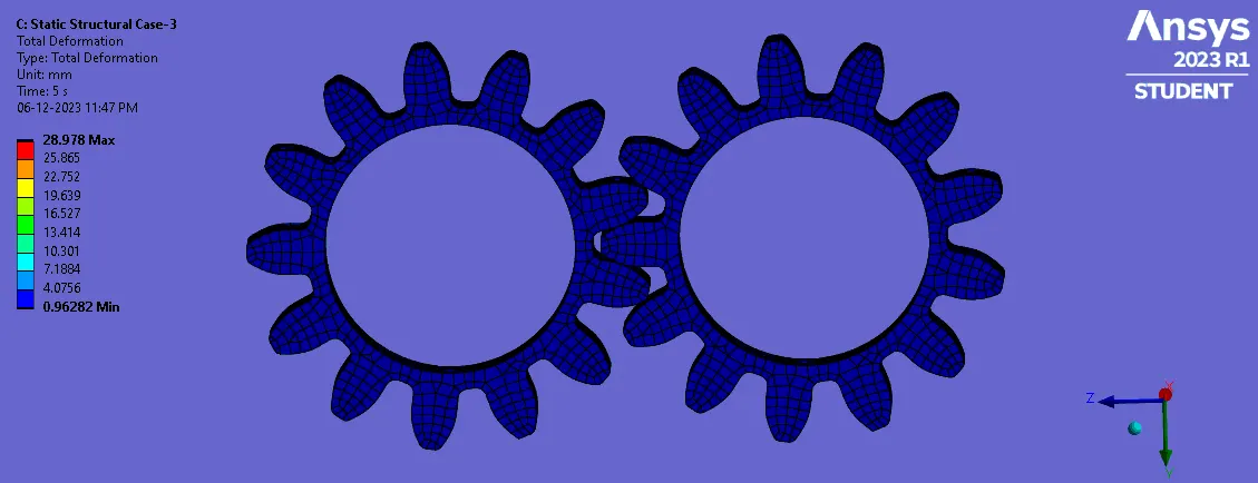
- The deformation acquired in all three cases is similar with the same boundary and loading conditions.
- The equivalent stress achieved in Case 2 is below the yield strength of its material. The equivalent stress obtained in Case 1 and Case 3 is beyond its yield stress.
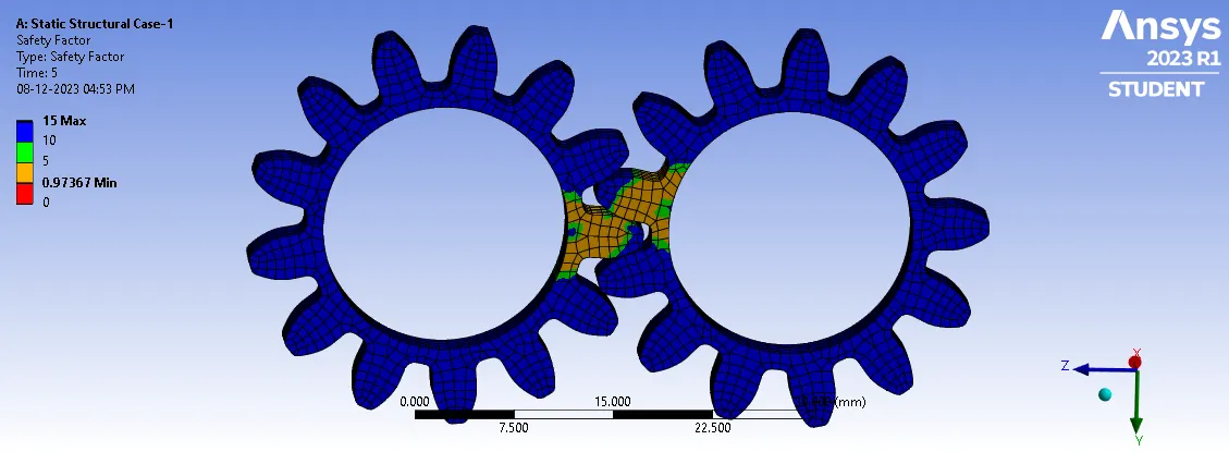
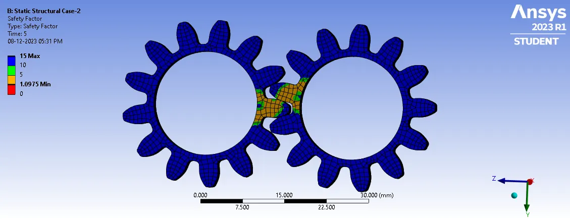
- The Factor of Safety computed from the results for Case 2 is more as compared to the other two cases.
- The elastic strain found in Case 2 is lower than in the other two cases.
- So eventually after comparing all the results, we finalized the Case 2 material (Cast Steel) as the better option in contrast to the other two materials.