Week - 5 - Modelling Spotwelds
SPOTWELD MODELLING USING BEAM AND SOLID ELEMENTS
INTRODUCTION
Spot welding (sometimes known as resistance spot welding) is a type of resistance welding. This welding procedure is typically used to join two or more metal sheets together by applying pressure and heat from an electric current to the weld region. Spot welds join surface pieces by welding them together at particular points. Spot welds can be used at any position on a surface portion or at any existing point. In LS-Dyna we primarily use 4 types of spotweld keywords given below:
- *MAT_SPOTWELD
- *CONSTRAINED_GENERALIZED_WELD_SPOT
- *CONSTRAINED_SPOTWELD
- *CONTACT_TIEBREAK_NODES
AIM:
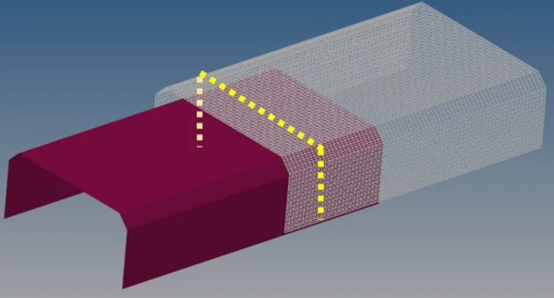
In this task, you will model spot welds for the specified part assembly and perform a crash test identical to the one in the crash box simulation. The graphic prescribed depicts the placement of the spotweld. The spotweld directions are shown by the yellow line. Before conducting the simulation, you must apply 3-7 symmetric spot welds along this line.
Spot welds should be represented independently utilizing beam and solid components. One solid element should be used per spotweld when employing solid elements. The axial and shear forces of the beam and solid components should be compared. The same *MAT SPOTWELD material card should be used for both beam and solid components. Steel material data for *MAT SPOTWELD cards can be used to calibrate the failure data based on your results. The ideal simulation should fail halfway through the execution duration.
DELIVERABLES:
- To create the Input .k file and output files (d3plot, glstat, sleout, rcforc)
- To perform the animation of the final simulation.
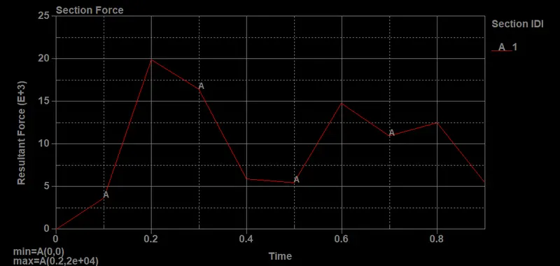
- To perform Cross-sectional force generated in the middle of the sheet metal (along its length)
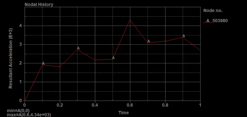
- To plot the Acceleration of a node in the middle of the sheet metal (along its length)
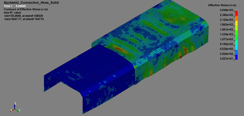
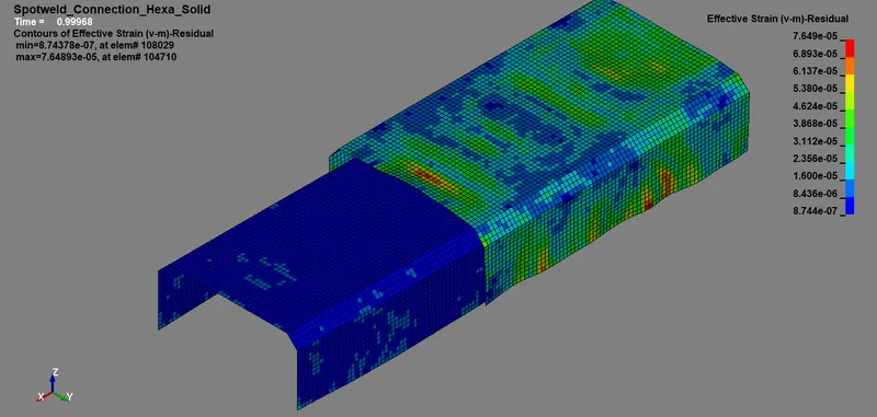
- To perform Maximum directional stress and strain along the length of the sheet metal (X strain, Y strain, etc)
- To plot all energies (total, internal, kinetic, hourglass, sliding)
- To compare the beam and solid elements spot weld results.
EXPLANATION:
Spotweld connection using beam elements
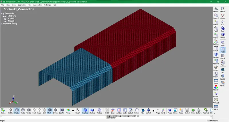
- The input .k file is imported in LS-Prepost and examined keenly. It comprises two sheet metal shell components laying over each other.
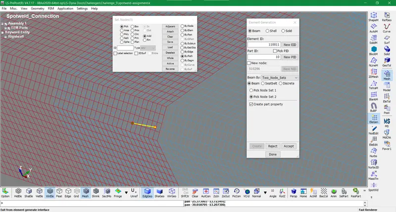
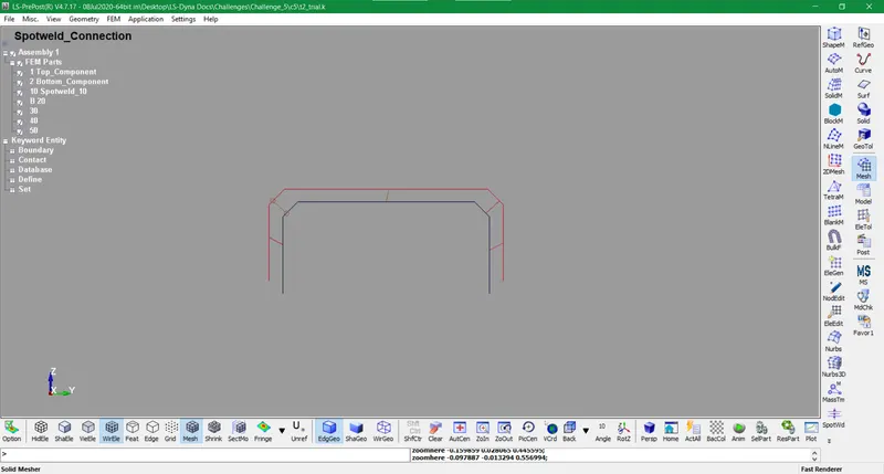
- The beam element is created using Mesh>EleGen tool at appropriate places. Two nodes are used to create it as the beam is a 1D element used in connections.
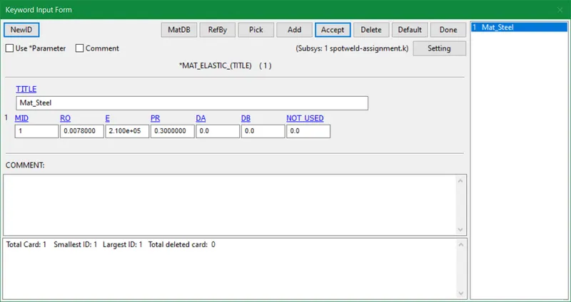
- Mat_100_Spotweld card is used for designating material for beam element. The values are being put for beam and shell w.r.t the unit system used i.e gm, mm, ms. The force and moments are also varied as per the requirement and type of element. Steel material is used for shell components with the Mat_Elastic keyword.
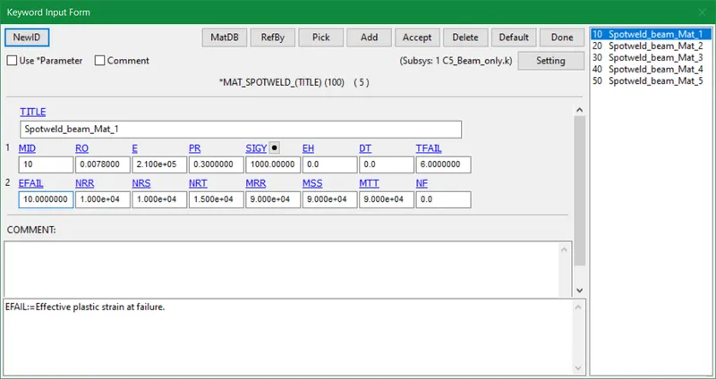
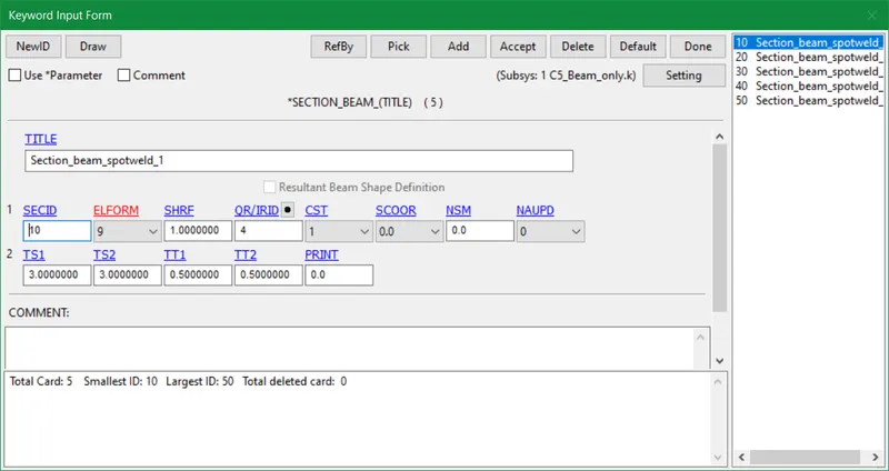
- The section keyword is adjusted with n number of beam elements developed. The element formulation type 9 (spotweld beam) is primarily used here for beam elements. The thickness for beam elements is assumed as 3mm in the section card.
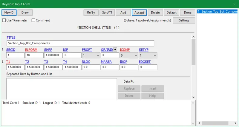
- The element formulation type 16 (Fully integrated shell element modified for higher accuracy) is used for shell components of this model to generate efficient results.
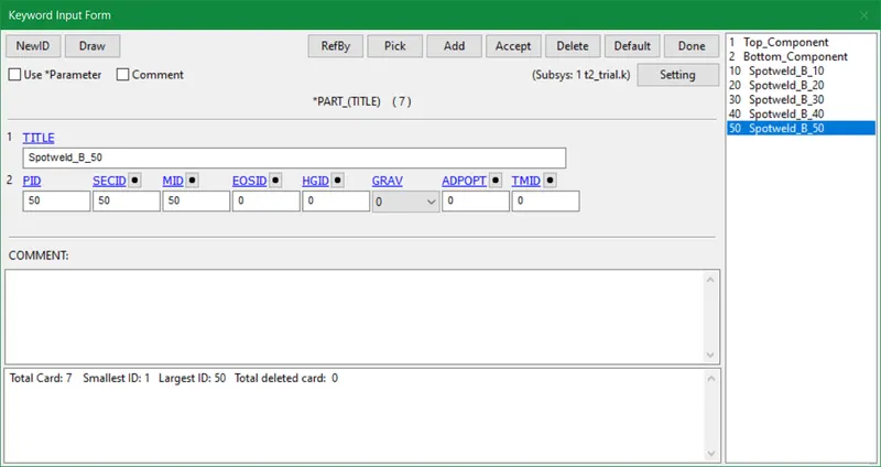
- Afterward, we assign all section and material ID's in part keyword cards.
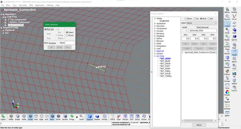
- The node set is created using Create Entity tool for beam elements to acquire a contact interface.
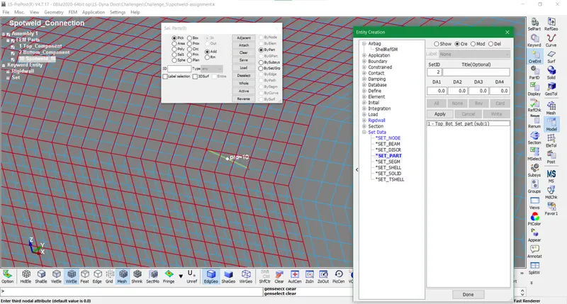
- The part set is created by the same Create Entity tool in EleTol for shell elements
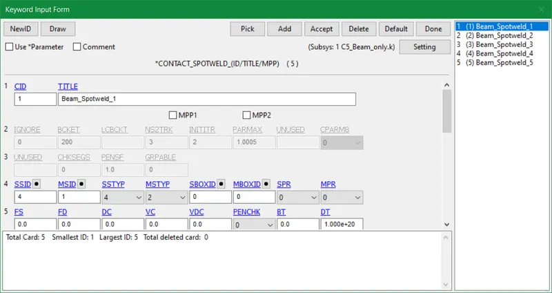
- After generating the node and part sets we assign a contact_spotweld card for our shell and beam elements. The shell elements are treated as master nodes and beam elements are treated as slaves.
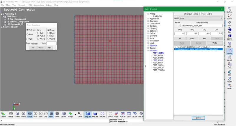
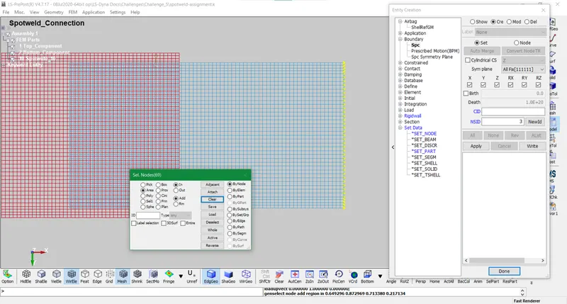
- Henceforth after providing the necessary contact, it is time for inputting boundary conditions by creating node sets for displacement nodes in the negative direction of x-axis. The shell components will move in a simulation in the direction of displacement nodes. We create spc node sets that is fixed and opposite to displacement nodes.
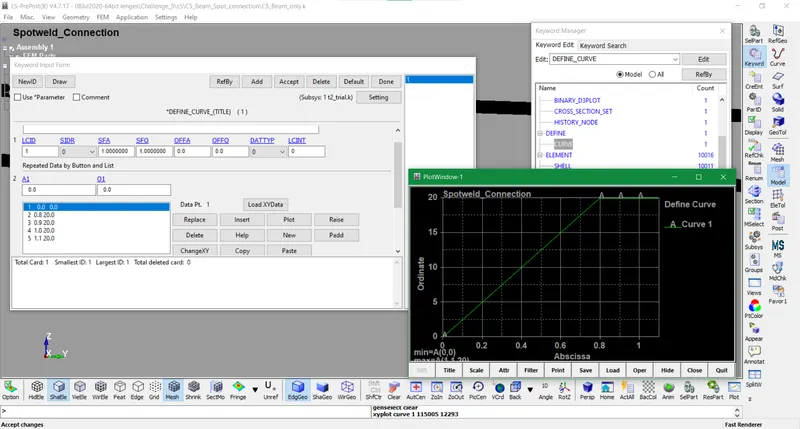
- The load curve is created according to the type of boundary conditions set up used in the post-processing.
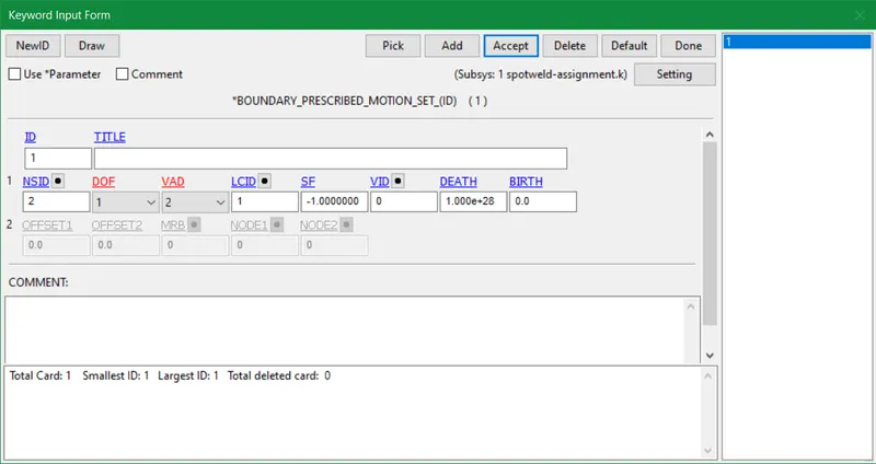
- The load curve displacement node set and SPC node-set are registered in boundary_prescribed_motion_set and SPC cards.
- Lastly, we give termination time, add binary_d3plot card and add nodes of a beam element in the history_node card to depict results for various parameters. A few ASCII databases are also added to compute the results of forces, energies, and other factors induced after stimulation.
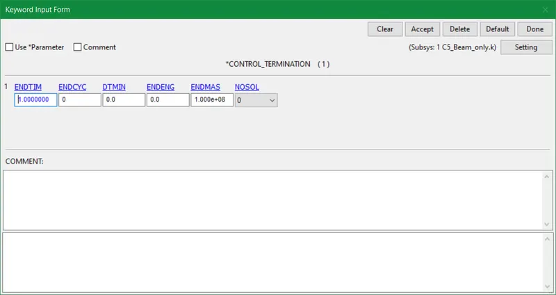
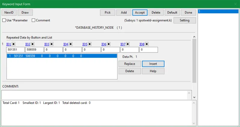
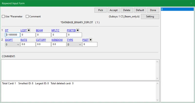
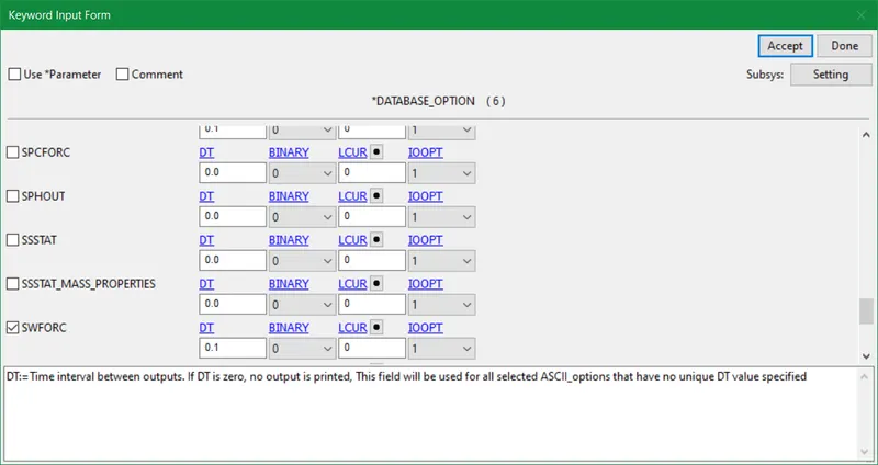
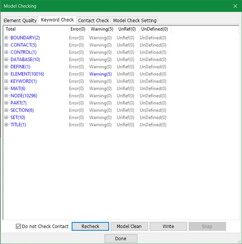
- Once all keywords are completed we do model checking in order to spot errors. Since no errors are procured so we run the simulation.
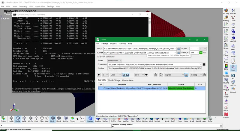
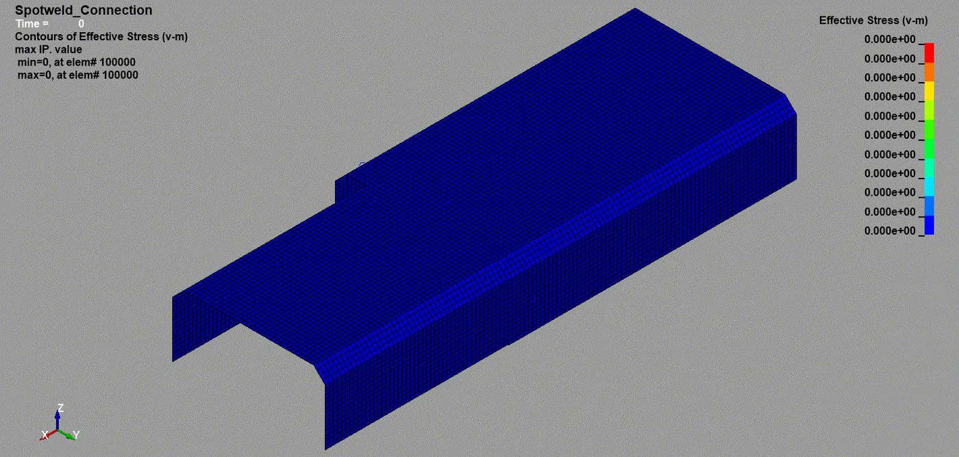
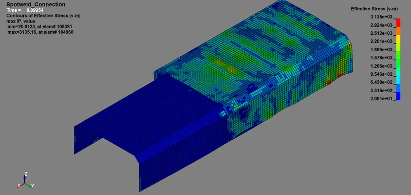
- The output command file displayed normal termination in the report. Henceforth the post-processing file depicting effective stress(Von_Mises) for spotweld using beam elements is portrayed below.
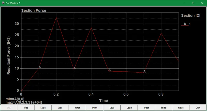
- The resultant force at the cross-section of the shell component is displayed below.
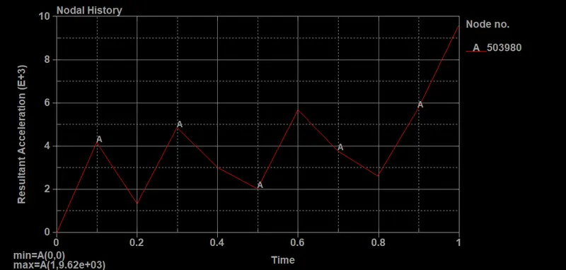
- The resultant acceleration at one of the nodes of the cross-section is portrayed below
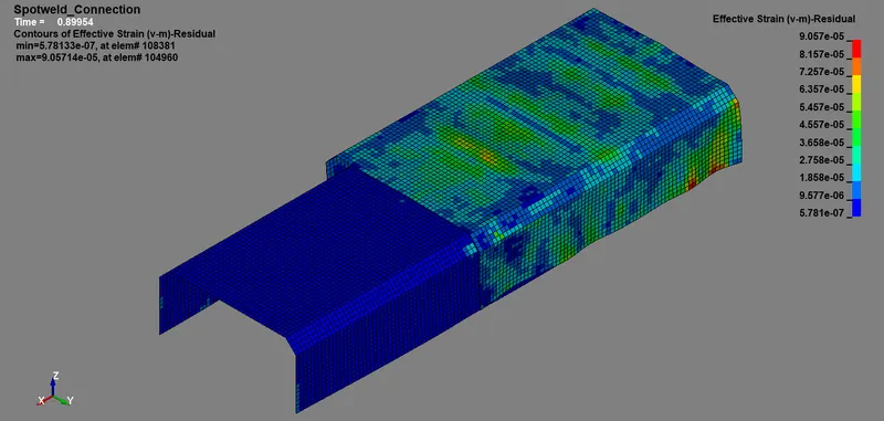
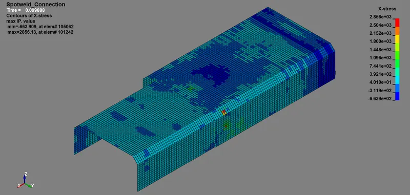
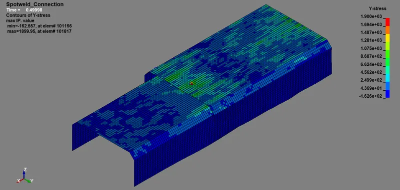
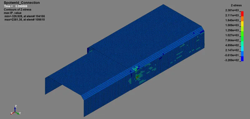
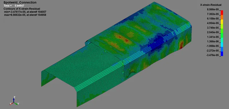
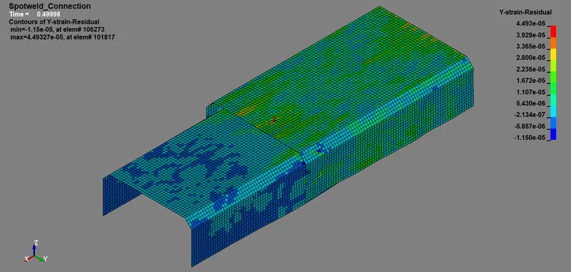
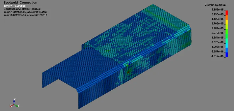
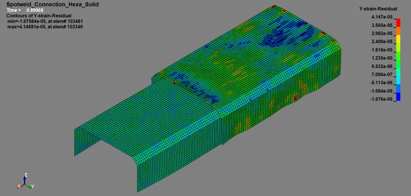
- The maximum directional stress and strains for the model are displayed below with these contours.
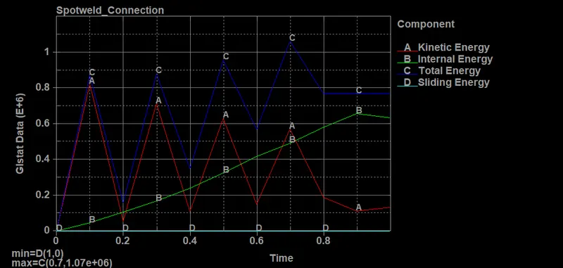
- Maximum Kinetic Energy, K.E = 8.25E+05 N-mm
- Maximum Internal Energy, U = 6.59E+05 N-mm
- Total Energy, E = 1.07E+06 N-mm
- Sliding Energy SE = 0 N-mm
- Maximum Hourglass Energy = 0 N-mm
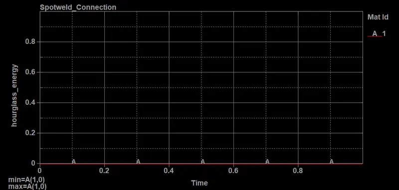
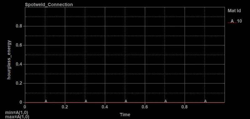
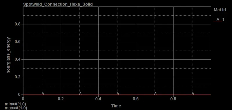
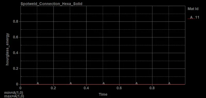
- The hourglass energies for both shell and beam elements are observed post-simulation and it is quite negligible.
Spotweld connection using Hexa solid elements
- In Hexa solid elements we only change some cards and parameters rest we follow everything like spotweld beam connection as aforementioned.
- The EleTool>EleEdit tool is used to create solid elements between two shell components or parts. So here we are using solid properties and elements that are also solid 3D elements in contrary to beam 1D elements.
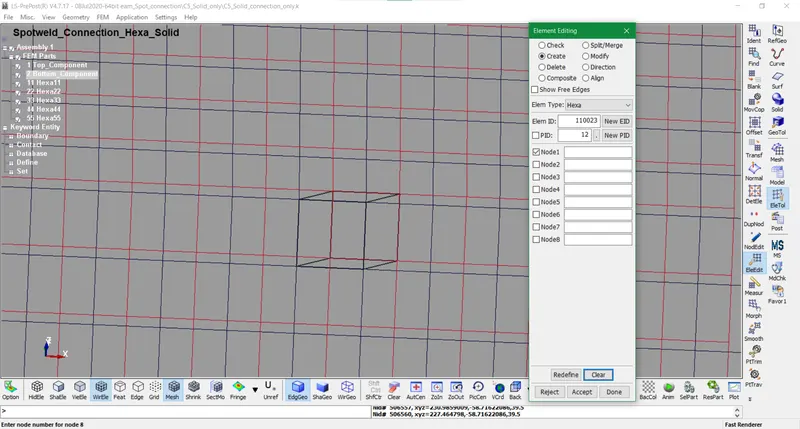
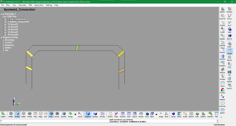
- In this model, 5 Hexa solid elements are generated like beam elements at respective points.
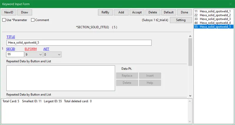
- The section solid card with Element formulation type 9 (point corotational for *MAT_MODIFIED_HONEYCOMB) is used in this kind of connection.
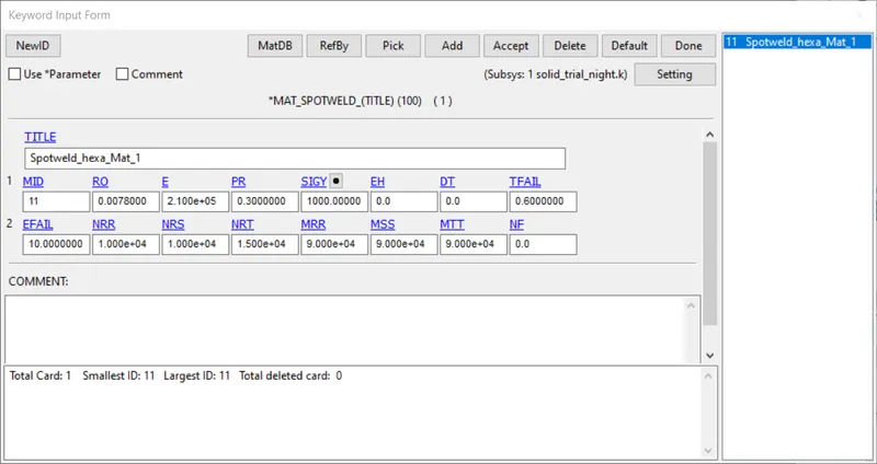
- The MAT_Spotweld card is used here in this case as well with changes in some values for forces and moments. We can also use a MAT_126 card in this case as it is more relevant to a solid shape.
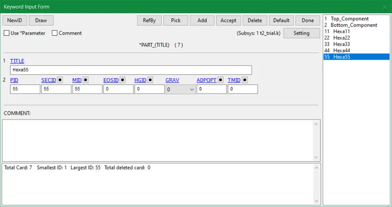
- In this scenario, we create solid sets for solid elements for creating slave segment sets in contact cards.
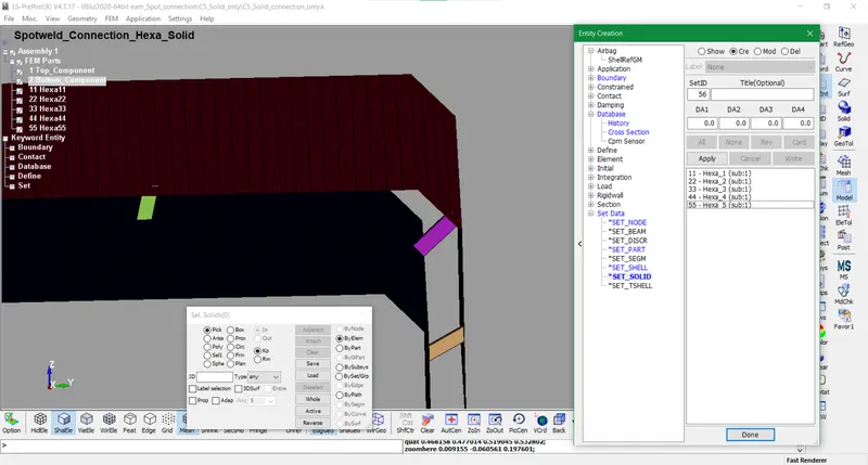
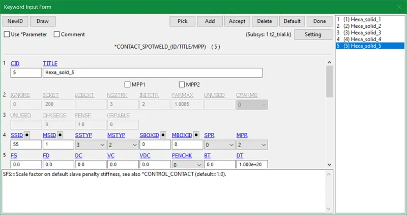
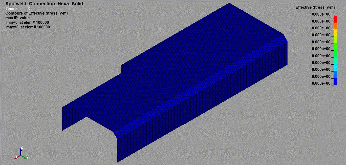
- Nevertheless, the rest all the cards and parameters are similar to beam element cards as mentioned earlier. So will run the simulation and the command output file showed a normal termination report. The effective stress(Von_Mises) is displayed below for solid element spotweld simulation.
- The deliverables for solid elements given below are likewise beam elements with differences in values.
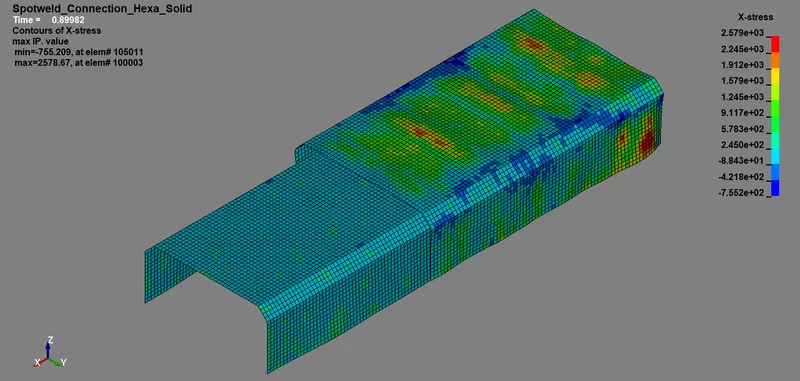
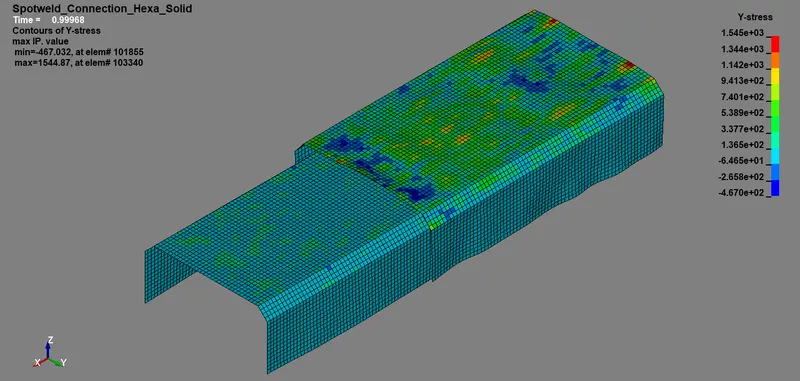
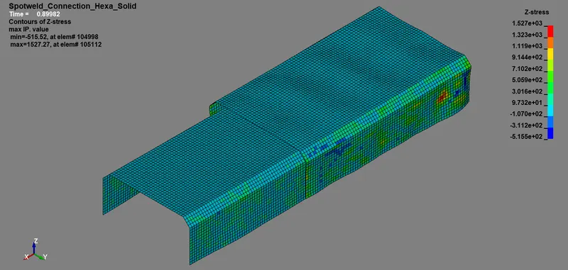
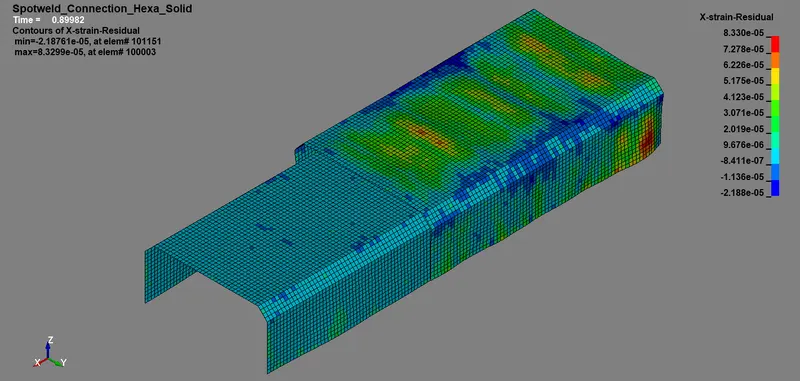
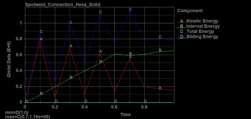
- Maximum Kinetic Energy, K.E = 7.82E+05 N-mm
- Maximum Internal Energy, U = 6.55E+05 N-mm
- Total Energy, E = 1.16E+06 N-mm
- Sliding Energy SE = 0 N-mm
- Maximum Hourglass Energy = 0 N-mm
Comparison of spotweld forces for solid and beam elements
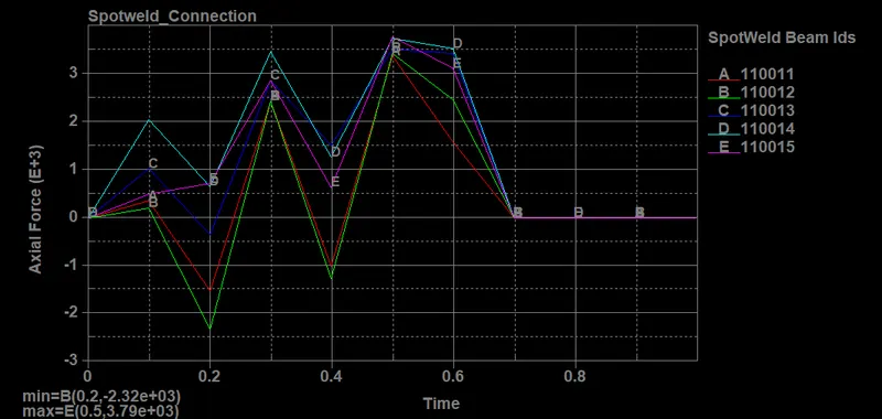
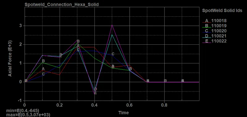
Axial Forces
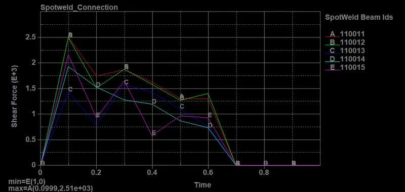
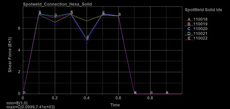
Shear Forces
CONCLUSION:
- The resultant acceleration and section forces developed in the middle of the shell component are more in beam element spot welds contrary to solid element spot welds.
- The effective stress, strains, and maximum directional stress-strains along the length of the model are more as well for beam elements.
- Except for kinetic energy rest of internal and total energy are more for solid elements in comparison to beam elements.
- Hourglass and sliding energies are zero for both elements implying an accurate analysis of base mesh surfaces.
- The axial forces induced post-simulation are found more in beam elements while shear forces are more in solid elements.