Week 12:Project 2-Meshing of Rear Wheel Holder challenge
2D Meshing of Rear Wheel Holder Using Hypermesh
INTRODUCTION
When smaller discrete cells are used to represent a broader geometric domain, the result is a mesh. Meshes are frequently used to produce computer images, solve partial differential equation solutions, and evaluate geographic and spatial analysis data. Model parts that are primarily two-dimensional, like sheet metal or a hollow plastic cape or casing, are represented by surface meshes or "shell meshes." When a more in-depth study is needed, a 2D mesh of elements can be created.
A Rear wheel holder features mounting brackets with L-shaped slots next to one end of the spare wheel support member. In order to position the support member at various heights above the vehicle's floor and support spare wheels of various densities, pivots positioned on the vehicle can be locked into place with the ends of either of the slot's legs.
A market-leading, multi-disciplinary finite element pre-processor called HyperMesh controls the creation of the largest, most complicated models, from the input of CAD geometry through the production of a solver file that is ready to run.
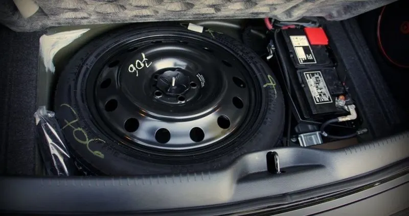
Figure-1 A real wheel holder or carrier in a modern car displayed in this picture
OBJECTIVES
- Generating Midsurface and geometry clean-up on the given component.
- Generating mesh on the given component with low tria concentration and proper mesh flow.
- Assign Thickness for the Midsurface
- Your model should pass all the given quality parameters.
Target Element Length = 5 Units
|
S.N |
Quality Criteria |
Value |
|
1 |
Aspect Ratio |
5 |
|
2 |
Skewness |
45 |
|
3 |
Warping |
15 |
|
4 |
Taper |
0.5 |
|
5 |
Min. Length |
2 Units |
|
6 |
Max. Length |
8 Units |
|
7 |
Min angle Quad |
45 |
|
8 |
Max angle Quad |
135 |
|
9 |
Min angle Tria |
20 |
|
10 |
Max angle Tria |
120 |
|
10 |
Tria % |
10 |
PROCEDURE
The coursework for the procedure is divided into the following phases in a sequential manner:
- We commence with the importing of CAD geometry with the Import geometry option in hypermesh. The model is in.IGES format that’s why we choose the import geometry option and hypermesh files are usually saved as with the .hm extension. Once it is imported we examine the physics of the model thoroughly and how to approach it. Afterwards, upon certain observation, we came across a lot of geometrical errors that need to be eliminated before advancing towards mid-surface generation. So we pursue manual geometric clean-up by using a set of hypermesh tools in the Geom panel. Most frequently we use quick edit tools, Surfaces, Surface Edit, Point edit, Edge Edit, Distance and Nodes while performing manual geometric clean-up. In many spots, surfaces were either absent or damaged so we rectified them by using the aforementioned tools. So we cleaned the parent geometry otherwise it might have affected the results of the mid-surface generated.
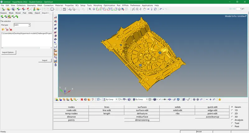
Figure-2 Importing rear wheel holder geometry in hypermesh
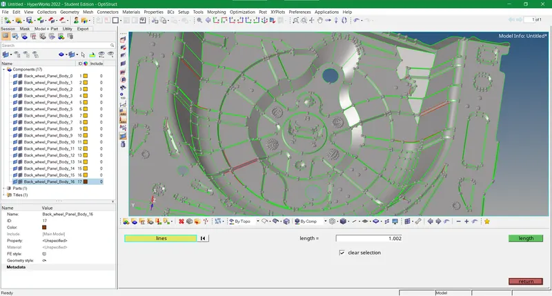
Figure-3 The parent geometric has many surface defects and deformations so manual geometric clean-up is used
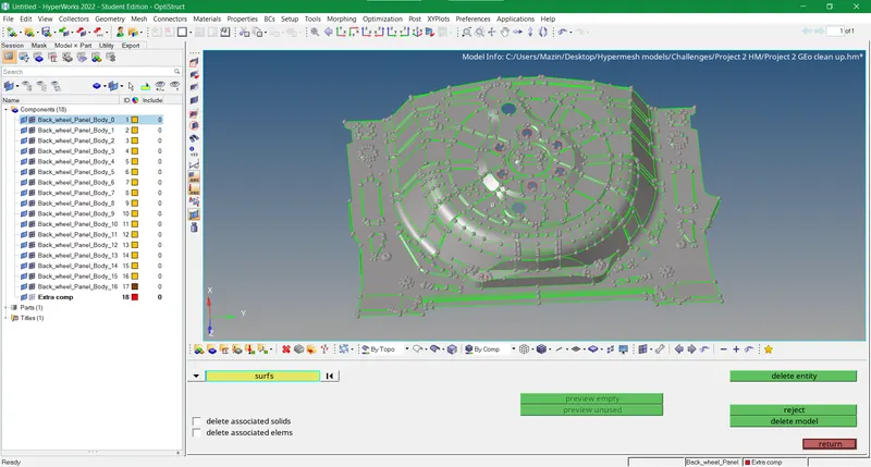
Figure-4 Manual geometric clean-up completed in the parent model
- However, after the geometric clean-up stage, we move to the next stage which is mid-surface generation. Before that, we calculate the thickness of the geometry in various areas by using the distance tool in the Geom panel of the Tools bar. The thickness came out to be uniform throughout the model so we used offset from the Surface edit sub-panel and after 4-5 minutes the mid-surface got generated. Some surfaces were distorted and damaged so we recreated and corrected them before approaching the next stage. After cleaning up we do mesh prepping by defeaturing the inappropriate lines and fillet areas or removing irrelevant surfaces to obtain good quality mesh flow.
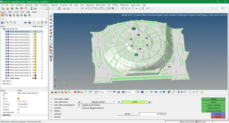
Figure-5 Extract the mid-surface of the whole model by offset tool as this is a sheet metal component.
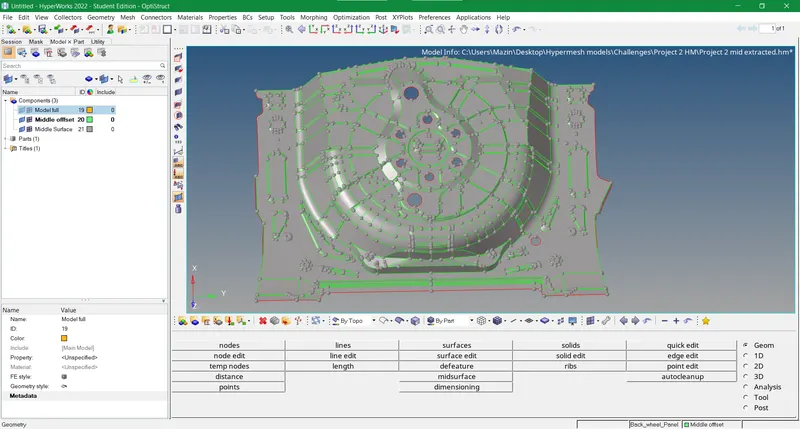
Figure-6 Mid-surface developed and some surface defects being rectified
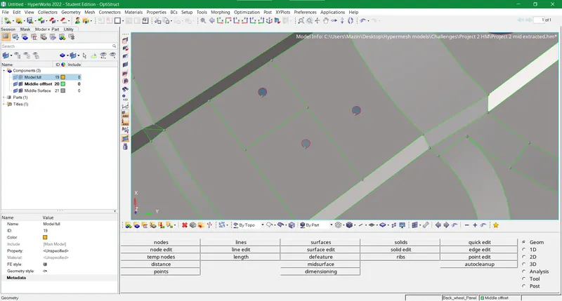
Figure-7 These small holes are patched as per the data provided
- Nevertheless, we pursue the final phase which is meshing. We use 2D-meshing in this assignment by using the 2D>Automesh tool and inputting given quality parameters in the criteria file. So we initiate the meshing gradually from one part to another and overcame many quality issues near narrow pointed corners of the surfaces. Hence we fixed quality mesh by certain tools viz. Quality index, edit-element, rebuild mesh, Smooth in the 2D panel and Translate in the Tool panel. Lastly, after completing meshing, we assigned property to our mid-surface component with the measured thickness.
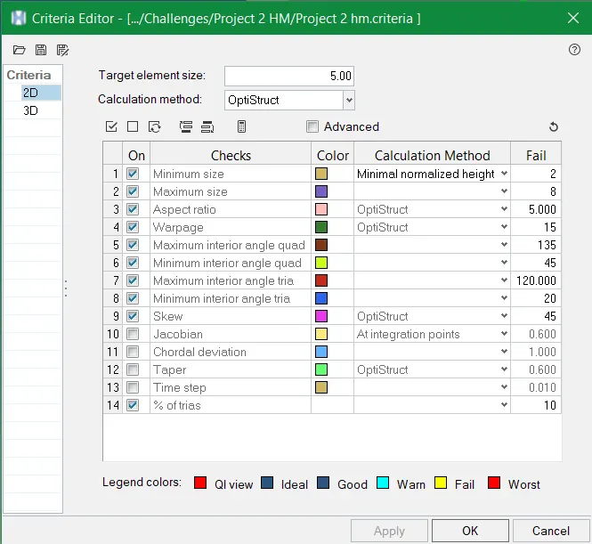
Figure-8 Enter all quality parameters in the criteria file as per allotted data
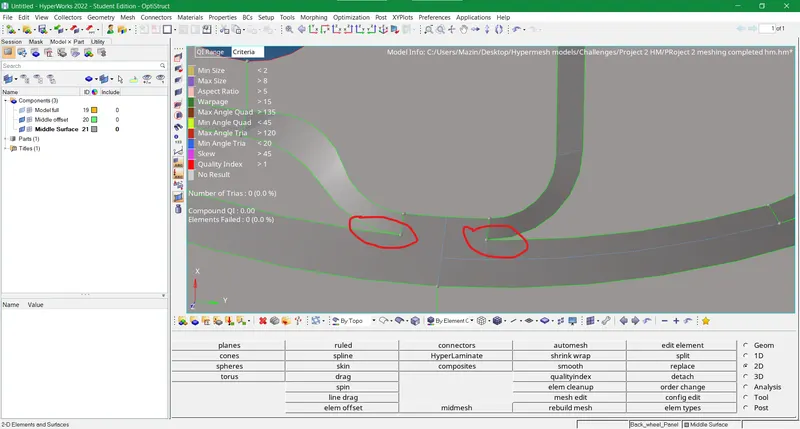
Figure-9 There are some narrow edges in this model where element quality errors might occur in mesh flow
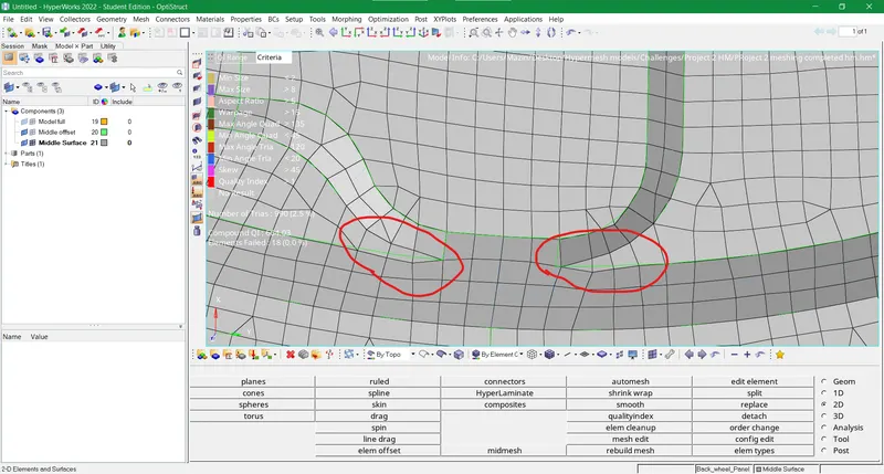
Figure-10 This area can be rectified by translating the nodes of those elements within a specific deviation to some extent and eliminating quality issues.
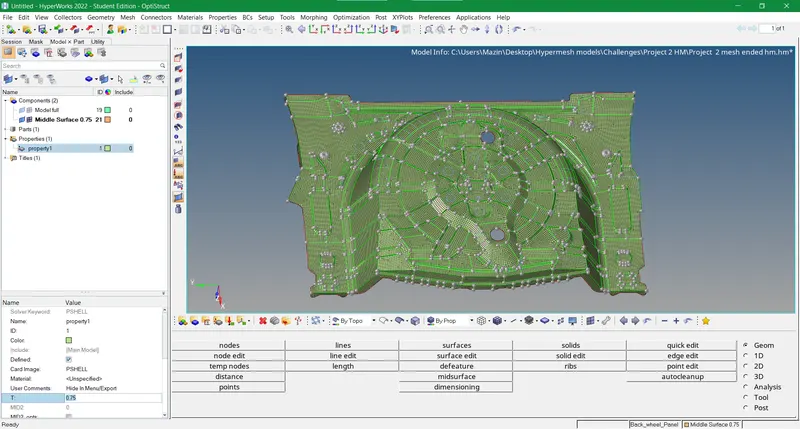
Figure-11 Property assigned with a measured thickness to the processed model
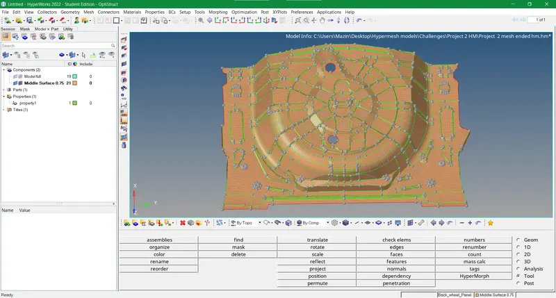
Figure-12 Final image of the component after meshing is done
RESULTS
- We worked on this sheet metal component with intricate geometry and it gave us a good experience to acquire better results for bigger models.
- The tria concentration attained was 2.7% which is quite acceptable from an industrial point of view and elemental errors were negligible.
- The user-defined splits and toggling of unneeded shaded edges on this complicated geometry provided better mesh flow.
- We assigned a thickness of 0.75 lastly to the mid-surface component that we developed for meshing.