Week- 5 - Solid meshing
SOLID MESHING OF REAR-VIEW MIRROR ASSEMBLY
INTRODUCTION
A rear view mirror is a device that allows a driver to look behind him or her. It normally hangs from the top of the cabin's windscreen. This is one of the vehicle's most basic but crucial safety equipment. It helps the driver with overtaking, parking in reverse gear, and other situations. With a unique sort of joint called a ‘swivel' joint, an anchor secures the rear view mirror to the windscreen. It enables the driver to adjust the mirror to his or her current seating position. In contrast to the plain glass used earlier, manufacturers now create mirrors with convex lenses.
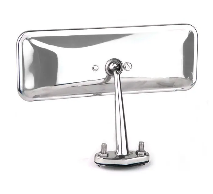
Figure-1 Large interior rear-view mirror
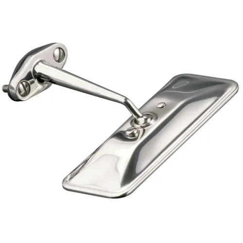
Figure-2 View from the back of the rear-view mirror
AIM
Examine for geometrical defects and mesh the Surfaces with the provided 2D element Quality criteria for the specified Rear view mirror component.
PROCEDURE
The entire procedure is carried out in the following order and broken into several stages:
- We initiated with Geometric clean-up of the whole CAD model and came across a lot of unnecessary triple cons and needle faces. We fixed them all automatically with the aid of ANSA and some manually. After clearing all major and minor defects and keeping design parameters in consideration we directly moved into the meshing phase.
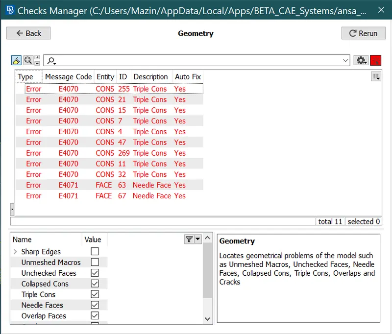
Figure-3 Geometrical errors check manager
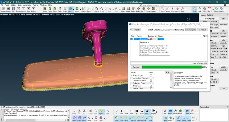
Figure-4 Geometrical defects all cleaned up for whole CAD geometry
- We will assign thickness and quality criteria given for the whole model before proceeding with meshing in this model. The average length for the model is used as 1 and the rest of the quantities are portrayed in the figures.
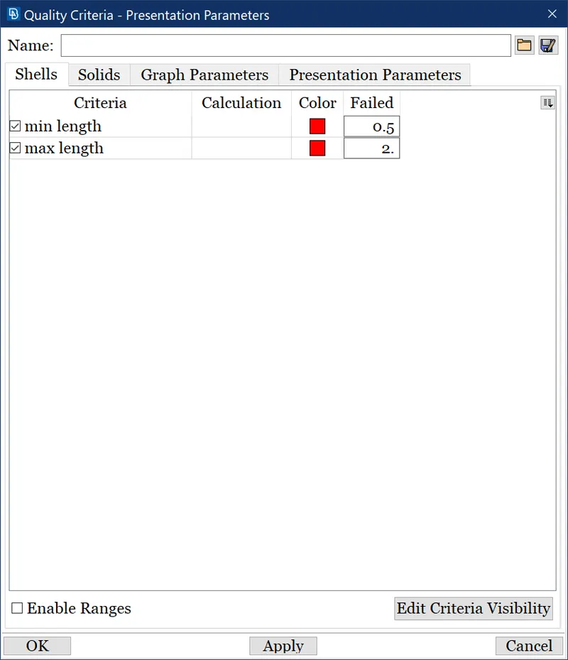
Figure-5 Quality criteria for surface meshing
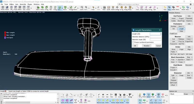
Figure-6 CAD model before thickness change
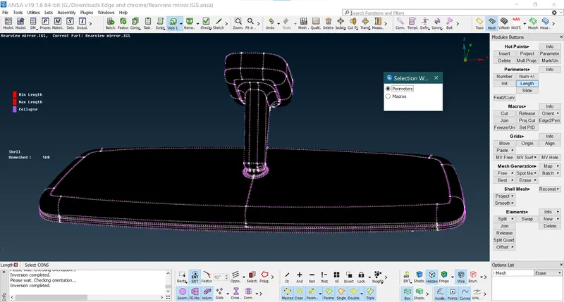
Figure-7 CAD geometry after thickness change to 1
- We divided the whole rear view mirror model into 4 parts so that it will be easy to work on it for meshing purposes. We set PIDs in the topo module for each entity as shown in the figure-8.
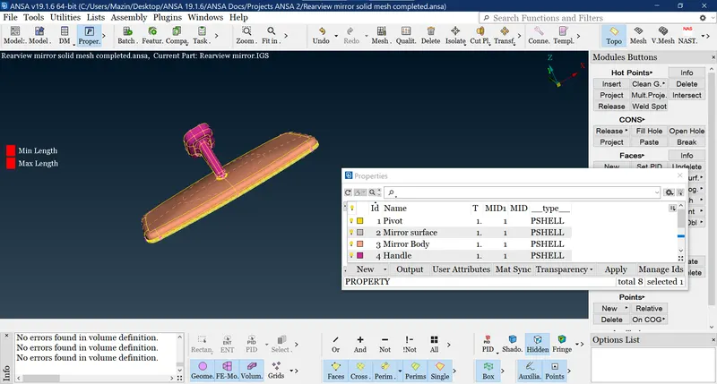
Figure-8 PIDs set for shell elements
- In solid meshing, we don’t need to extract a mid-surface rather do surface meshing on the model sections first and then go for volumetric meshing. We use tria and ortho tria elements for meshing in this model or more precisely unstructured mesh. Since ANSA takes a lot of time to process tetra mesh so on flat surfaces we use tria elements and for edges, fillets or inclined surfaces ortho tria’s are recommended. Also, tetra mesh captures properly onto the edges whilst tria’s give optimum result for flat surfaces. Nevertheless, we input mesh parameters and go on with the surface meshing of all 4 entities gradually.
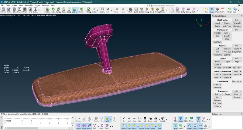
Figure-9 2D-meshing done for shell elements
- After completing the 2D meshing of surfaces of the whole model we only check for min and max length for off-element failures. Once the phase is done we proceed towards volumetric mesh but here we need to set new PIDs for an undefined volume that we were working on until now. In the V.mesh module, we go to the Volume section and choose the Define option and form a properly defined volume to mesh upon from the inside. Either we do re-meshing inside the V.MESH MODULE>VOLUME>LIST for solid PIDs or manually by choosing V.MESH>UNSTRUCTURED MESH> TETRA RAPID/TETRA FEM to get a specified solid mesh flow.
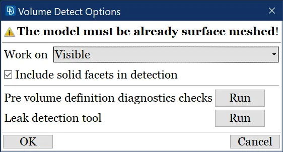
Figure-10 Define volumes and procession of solid meshing
- The PIDs for new solid meshed parts and solid meshing for each part are displayed below in the figures. Also, we only check tetra collapse for off-element failures in solid meshing which are fixed either by V.MESH MODULE>IMPROVE>FIX QUALITY or MESH MODULE>GRIDS.MOVE/MV FREE
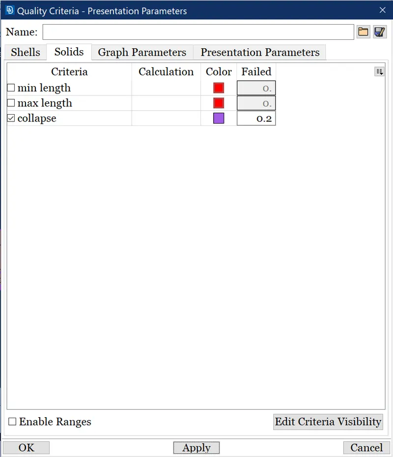
Figure-11 Quality Criteria for tetra mesh/solid meshing
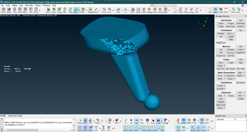
Figure-12 Solid meshing of the rear-view mirror handle sectioned from sideways of the base
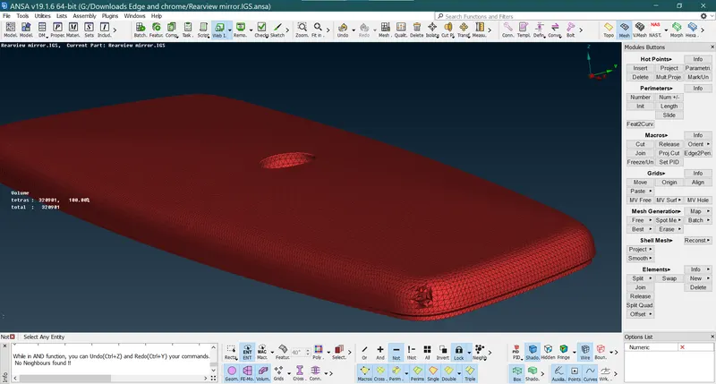
Figure-13 Solid meshing of the rear-view mirror body sectioned at the fillet of one corner
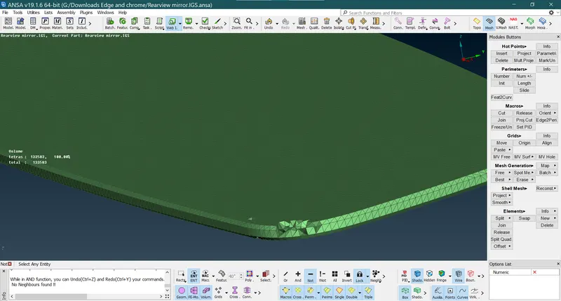
Figure-14 Solid meshing of the rear-view mirror surface sectioned on one of the edges
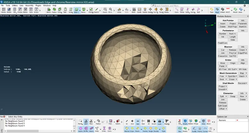
Figure-15 Solid meshing of the rear-view mirror pivot sectioned on the perimeter surface
LEARNING OUTCOMES
- In this project, we got a basic understanding of solid meshing and learned the usage of tria elements in meshing. Also, the height factor for tetra elements gave us a brief outlook of practical designs used in the mechanical domain from pre-processing to post-processing tools.
- The tetra elements and tria elements can be used on edges or flat surfaces and vice versa in accordance with mesh flow and design specifications of the respective model.
- We used unstructured mesh or tetra mesh in this model which was actually in a haphazard manner from centre to outer periphery in solid parts.
- The raised edges and kinks are avoided on solid surfaces to get uniform mesh flow in a definite path from above.
- The features should capture at least two rows of mesh elements in volume meshing to get better performance in further analysis.
CONCLUSION
- Cleaned up all geometric errors for the whole rear view mirror assembly thoroughly and rechecked again after meshing to get optimum results.
- Assigned PIDs for both shells as well as solid entities of the whole assembly.
- First started with the 2D meshing of tria and ortho-tria elements on surface shells then terminated with tetra mesh for defined volumes yielded from shell entities.
- Off elements in solid meshing are min or max length and tetra collapse which is eradicated by necessary methods.