Week - 4 - Crash Box Simulation
CRASH TEST FOR CRASH BOX OF RECTANGULAR CHANNEL
INTRODUCTION
The student's task in this assignment is to recreate a crash test for a crash box using the provided model.
A crash box is a strong energy-absorbing structure that collapses when stresses are applied, minimizing the damage to neighboring components.
Although a fully developed crash box is a rather complex design, in this case, we will choose a rectilinear channel, which can be regarded as the most basic crash box.
ASSUMPTIONS:
-
The crash box should crash into a rigid wall created using the *RIGIDWALL_ keyword. Check the manual to understand and create a rigid wall.
-
The material for the crash box is steel. The simulation needs to be started using elastic material to verify its correctness and later a nonlinear material card data will be provided. The thickness of the crash box is 1.2mm.
-
The initial velocity for the crash box should be around 50 kmph
-
The units system to be used is gm-mm-ms
-
The simulation should satisfy either of the two situations - (1) It crashes on the rigid wall and rebounds completely or (2) it buckles and folds in the axial direction so as to come in self-contact.
-
Once the simulation is completed and results, as asked for below, are collected, run another simulation by increasing the thickness of the crash box from 1.2 to 1.5mm.
AIM:
- - Input .k file and output files (d3plot, glstat, sleout, rcforc)
- - Animation of the final simulation
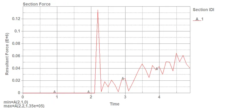
- - Cross-sectional force generated in the middle of the crash box (along its length)
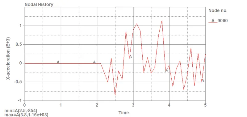
- - Acceleration plot of a node in the middle of the crash box (along its length)
- - Maximum directional stress and strain along the length of the crash box (X strain, Y strain, etc)
- - Plot of all energies (total, internal, kinetic, hourglass, sliding)
- - Compare the accelerations and stress/strain plots of 1.2/1.5mm crash boxes.
EXPLANATION:
The solving and post-processing used in this assignment are devised in order of steps as follows:
- Import Keyword format file (.k) into LS PrePost software.
- Put it in an isometric view in order to get a better visualization of the model for further processing.
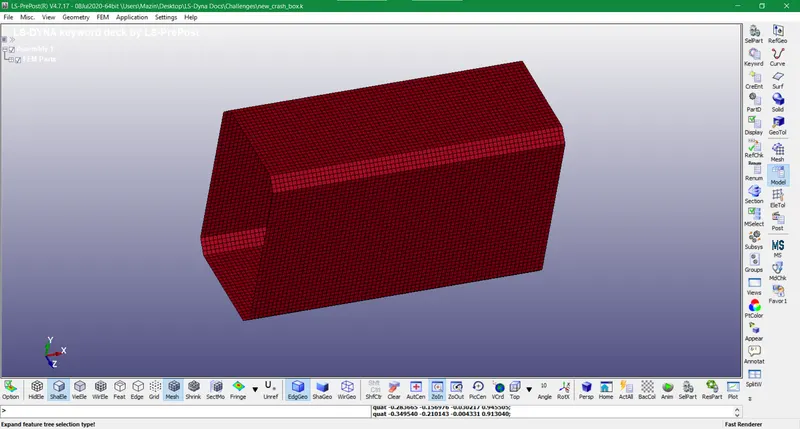
- So we check the model keywords that are by default given in the file and start adding the data for the necessary keywords.
- It is done by clicking on the keyword icon on the side menu.
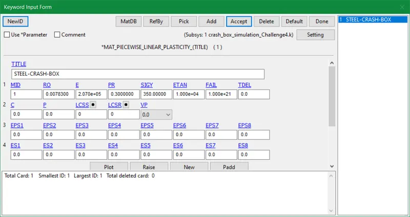
- Starting by material keyword in the keyword manager we use MAT 024 card i.e linear plasticity.
- We designate 1 for Material ID and provide the specific values.
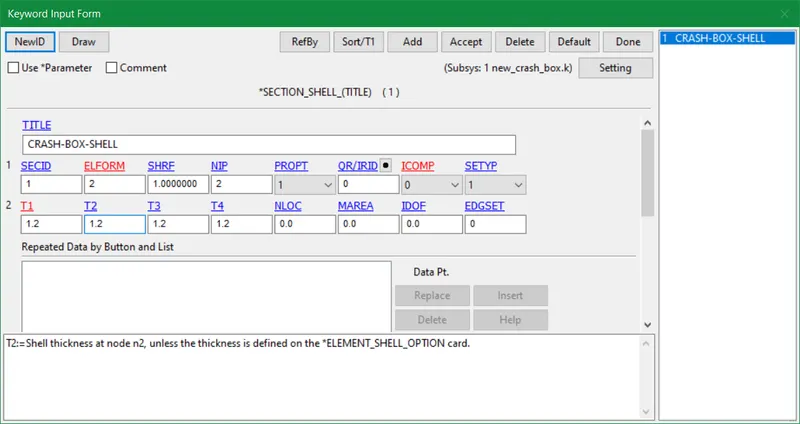
- The section card with shell cross-section is assigned with 1.2mm thickness. Later we change to 1.5mm thickness after completing the whole solving process.
- Section ID is designated as 1
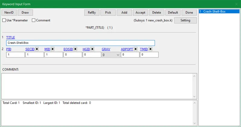
- The Part ID distinguishes different parts or properties in a model. Section ID and Material ID are incorporated in it depending on the material like steel, aluminum, etc, or section as shell, solid, etc.
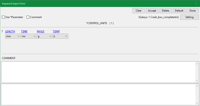
- In the Control keyword, we choose Units and put on desired parameters according to the requirement for the model.
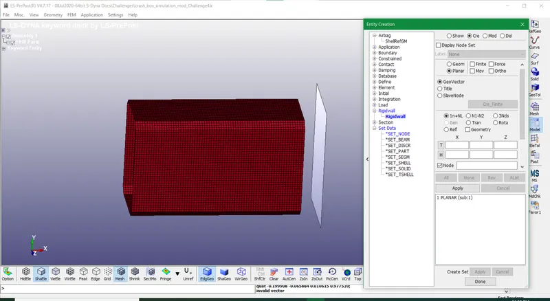
- We create a rigid wall from Model>Create Entity>Rigidwall by using the Planar option and clicking on the desired face of the crash box as shown below. Then we use the Translate vector to move the rigid wall to a particular coordinate axis w.r.t to the analysis parameters.
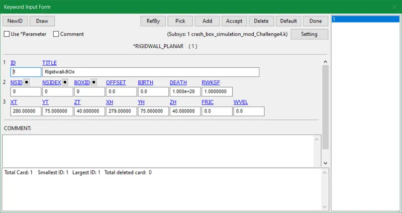
- The rigid wall is designated to the Rigidwall_planar keyword in the keyword manager as shown below. The tail and head vectors of the component that strikes the rigid wall are accordingly adjusted so as to attain a proper rebounding motion.
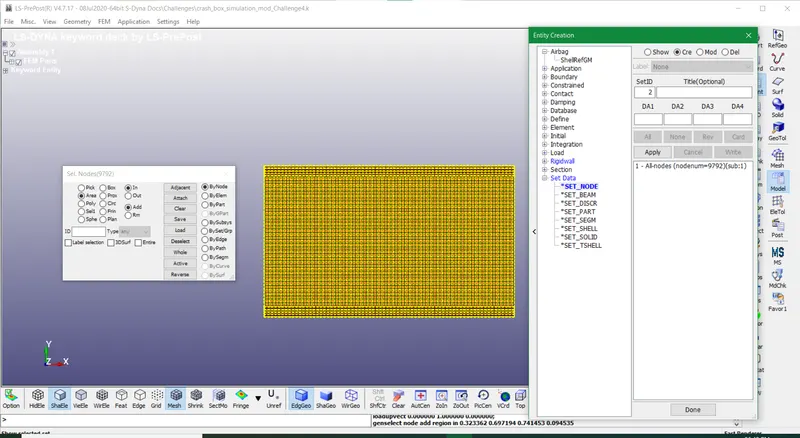
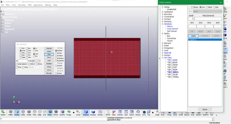
- The set_node and set_shell of the crash box are created to ensure an interface between the rigid wall and the crash box. Also to specify energies, velocity, acceleration, stresses, strains so forth, and so on attained post-solving.
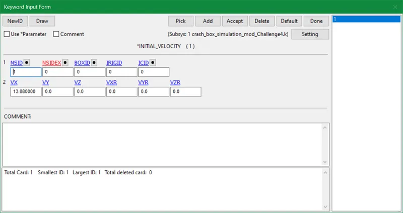
- The initial velocity in Initial_velocity keyword is inputted in the direction of impact between the crash box and the rigid wall. Also, it is changed from 50kmph to 13.8 mm/ms^2 as per given unit system
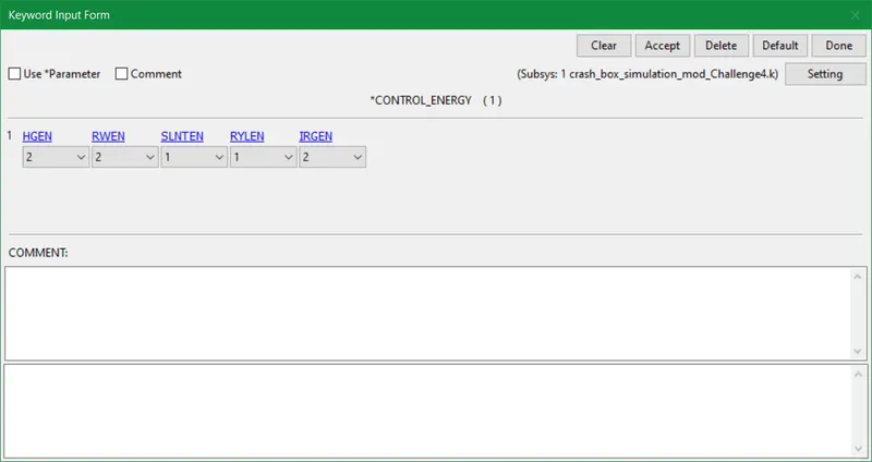
- CONTROL_ENERGY gives alternatives for regulating energy dissipation.
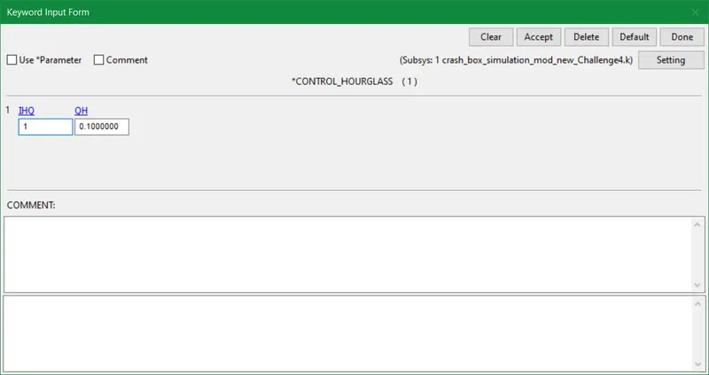
- Hourglass control is the addition of viscosity or stiffness to hexahedral solid and quadrilateral shell parts that employ decreased integration. It also applies to shells made with formulation 1 t. These substances wouldn't have any energy deformation modes without hourglass control, which might cause them to enlarge and decimate the solution.
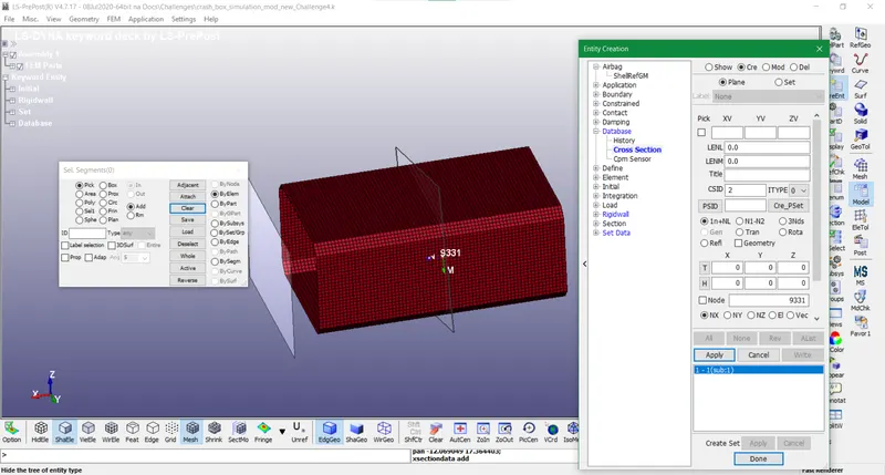
- The cross-section is developed using create entity option from the model tool as shown below. We select any point and a normal in the middle of anywhere in the crash box to generate a cross-section.
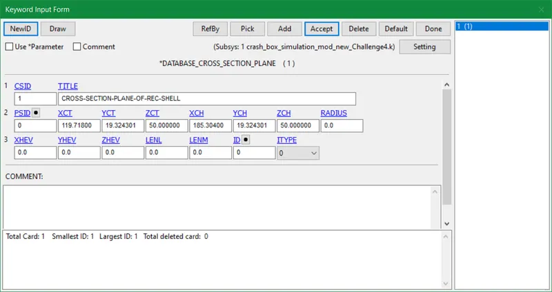
- In the database_cross_section_plane keyword, the cross-section ID is entered and accepted for further processing.
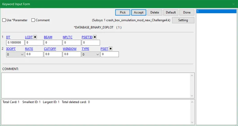
- DATABASE_BINARY_D3PLOT requests binary output and comprises the database for the whole model. The time interval between outputs is inserted as well in the binary d3plot keyword.
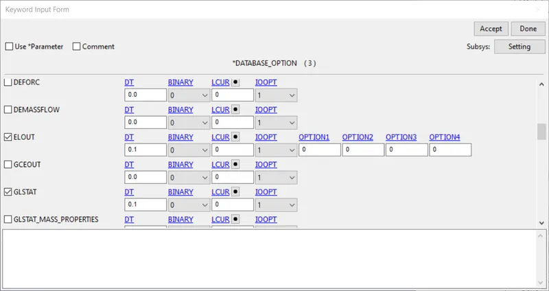
- DATABASE_OPTION determines the type of database required like the items given in the below list that we use for this model:
- ELOUT: Element data
- GLSTAT: Global statistics and energies
- MATSUM: Part energies
- RCFORC: Resultant contact interface forces.
- RWFORC: Rigidwall forces.
- SECFORC: Cross-section forces.
- SLEOUT: Contact interface energies.
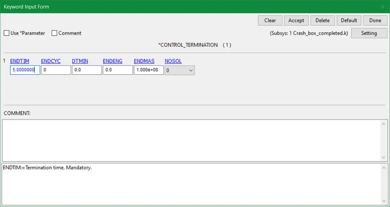
- The termination time is defined by means of velocity and displacement for the crash box. It is mandatory to input the CONTROL_TERMINATION keyword.
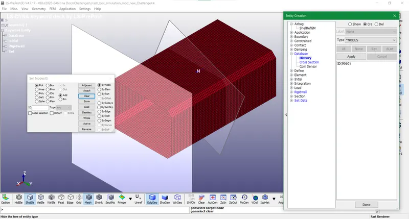
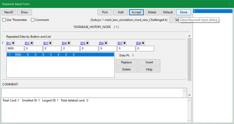
- The history node is designated in the cross-section area so as to obtain results later on for various parameters and compare them in terms of physical standards and configuration. It is assigned in the DATABASE_HISTORY_NODE card and moved on to the final step prior to post-processing.
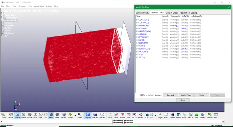
- Henceforth, model checking is done using a tool MdChk in order to spot any errors before running the simulation. If there are no errors found then we can proceed with running the simulation.
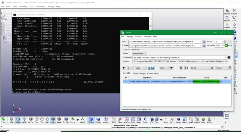
- The cmd file portrays normal termination results which means the simulation is gone in an effective manner.
DELIVERABLES:
Animation of the final simulation
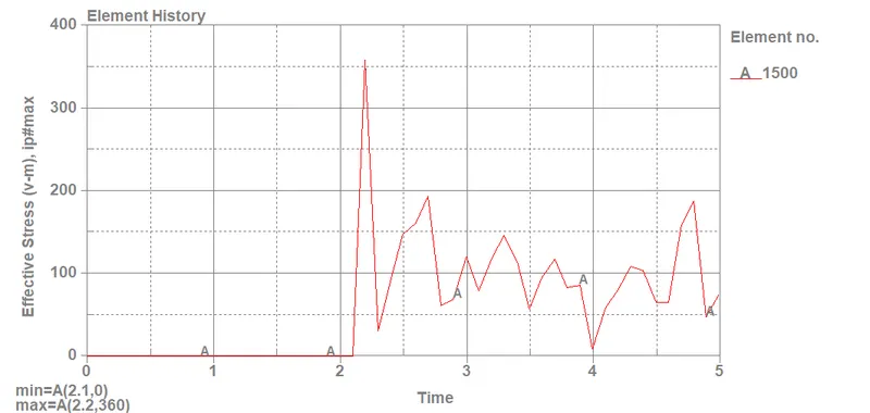
- In the final simulation file, we obtained maximum and minimum effective stress values at 1500 and 89 elements respectively for both 1.2mm and 1.5mm thickness crash boxes.
-
For 1.2mm, Maximum stress (v-m) σmax = 359.7 MPa
-
For 1.5mm, MAximum stress (v-m) σmax = 360.08 MPa
-
For 1.2mm, Minimum stress (v-m) σmin = 0 MPa
-
For 1.5mm, Minimum stress (v-m) σmin = 0 MPa
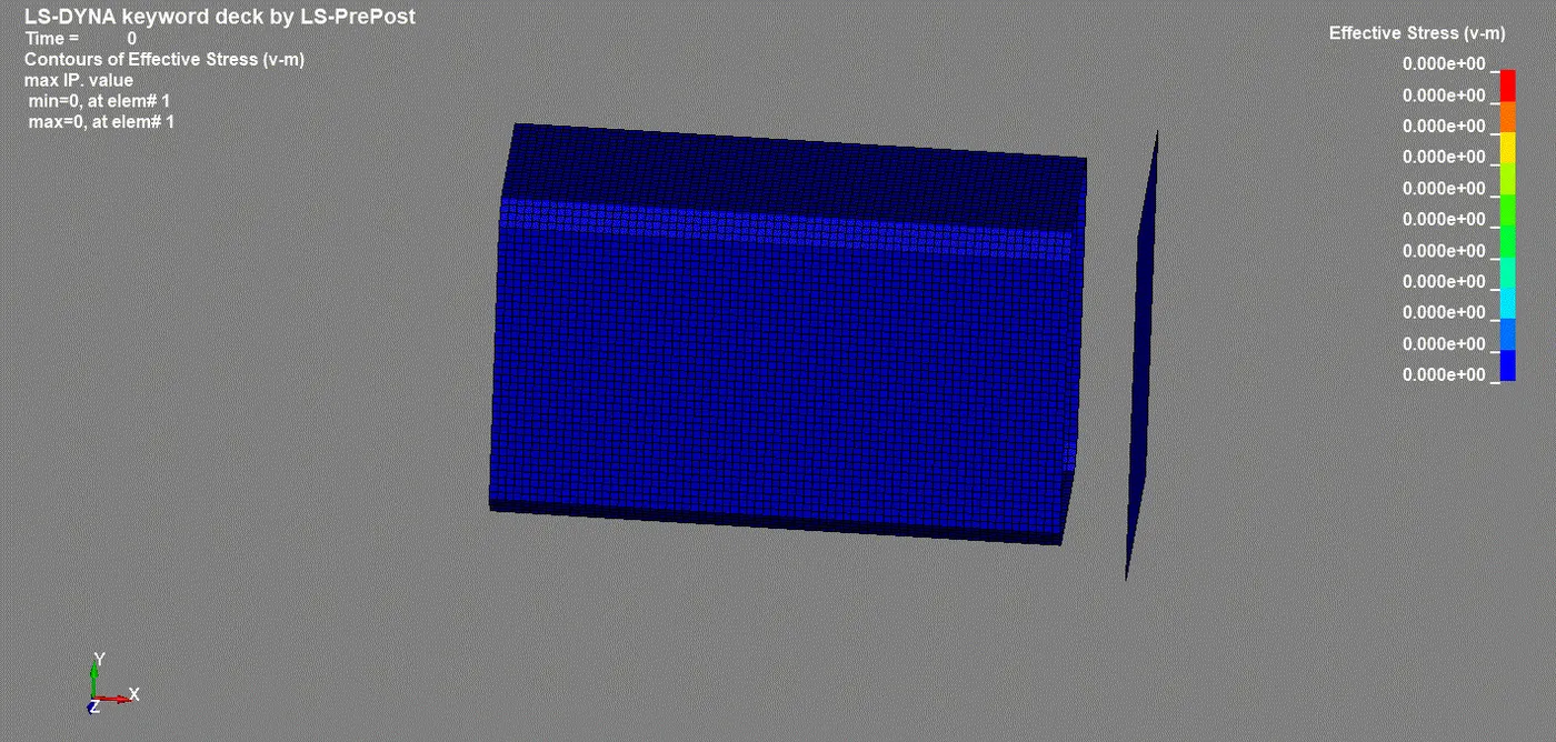
- Henceforth we saw there isn't much difference in max and min stress values for the prescribed thicknesses.
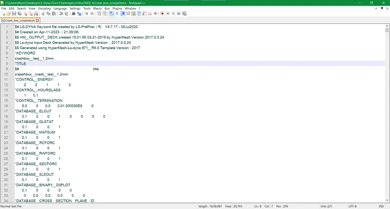
Keyword text file for 1.2mm thickness crash box
- In the keyword text file, we get a summary of all keywords used in the model for solving and post-processing. We can adjust the title, section, mat, and other keyword parameters used in the model for post-processing.
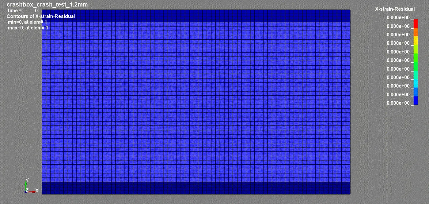
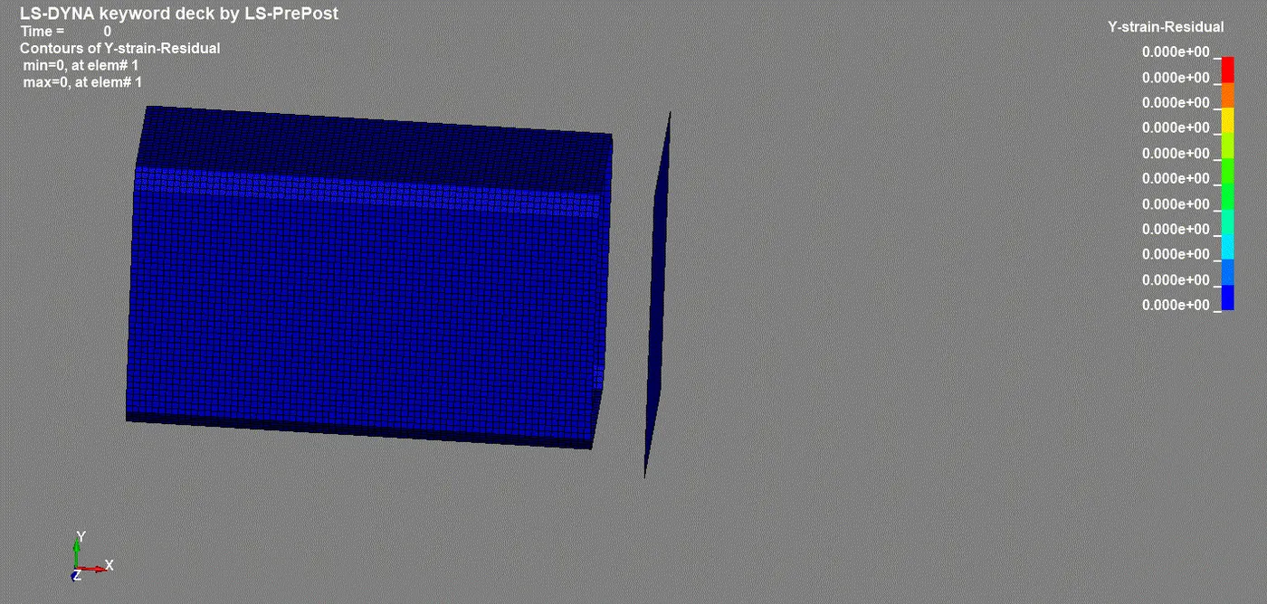
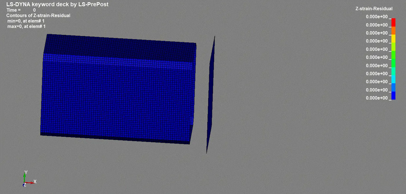
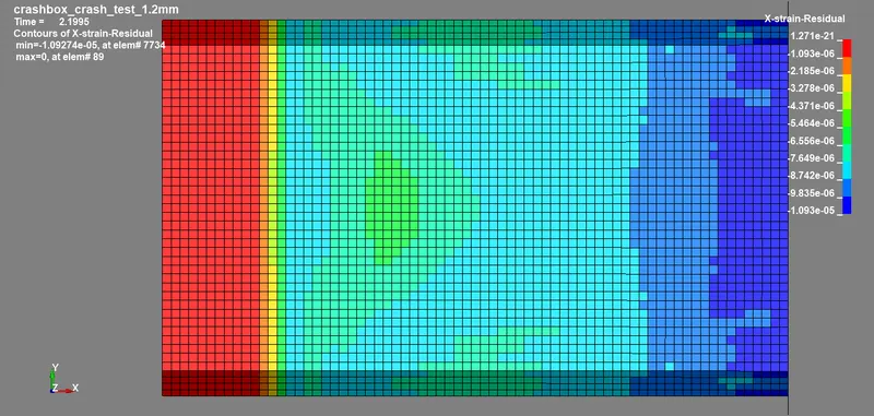
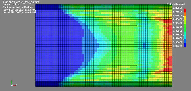
Residual strains in X, Y, and Z coordinates for 1.2mm thickness crash box
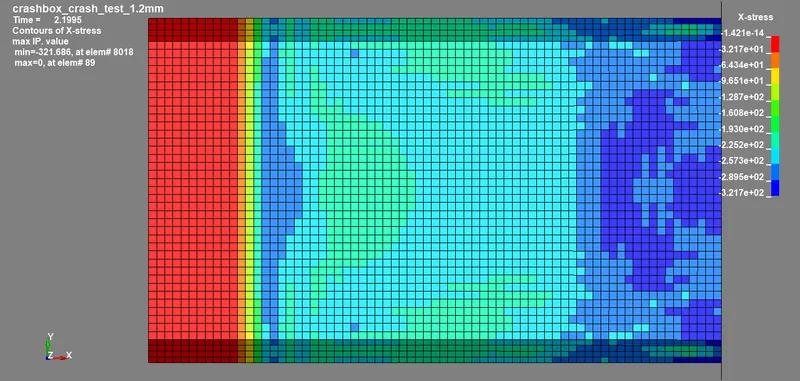
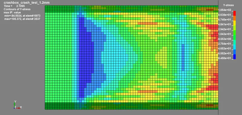
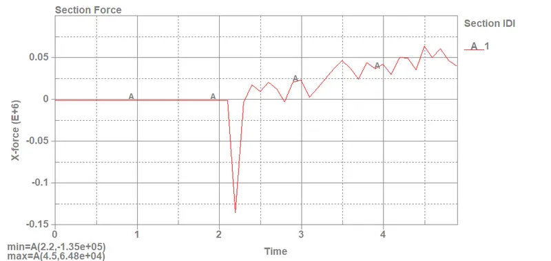
- The maximum directional stress and strain along the length of the 1.2mm thickness crash box are displayed below in the given images w.r.t the particular elements.
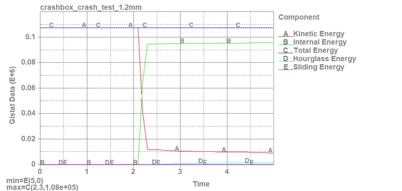
Glstat energies for 1.2mm thickness crash box as per prescribed data is given as:
- Maximum Kinetic energy, K.E = 1.08e+05 gm mm2/ms2
-
Maximum Internal Energy, U = 9.62e+04 gm mm2/ms2
-
Total Energy, E = 1.08e+05 gm mm2/ms2
-
Maximum Hourglass Energy, HG = 1.61e+03 gm mm2/ms2
-
Sliding Energy, SE = 0 gm mm2/ms2 (Positive value means the contact between rigid wall and crash box was successful)
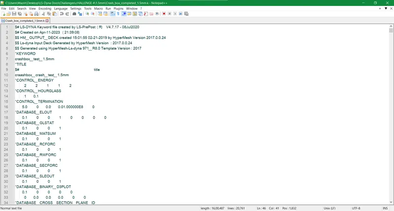
Keyword text file for 1.5mm thickness crash box
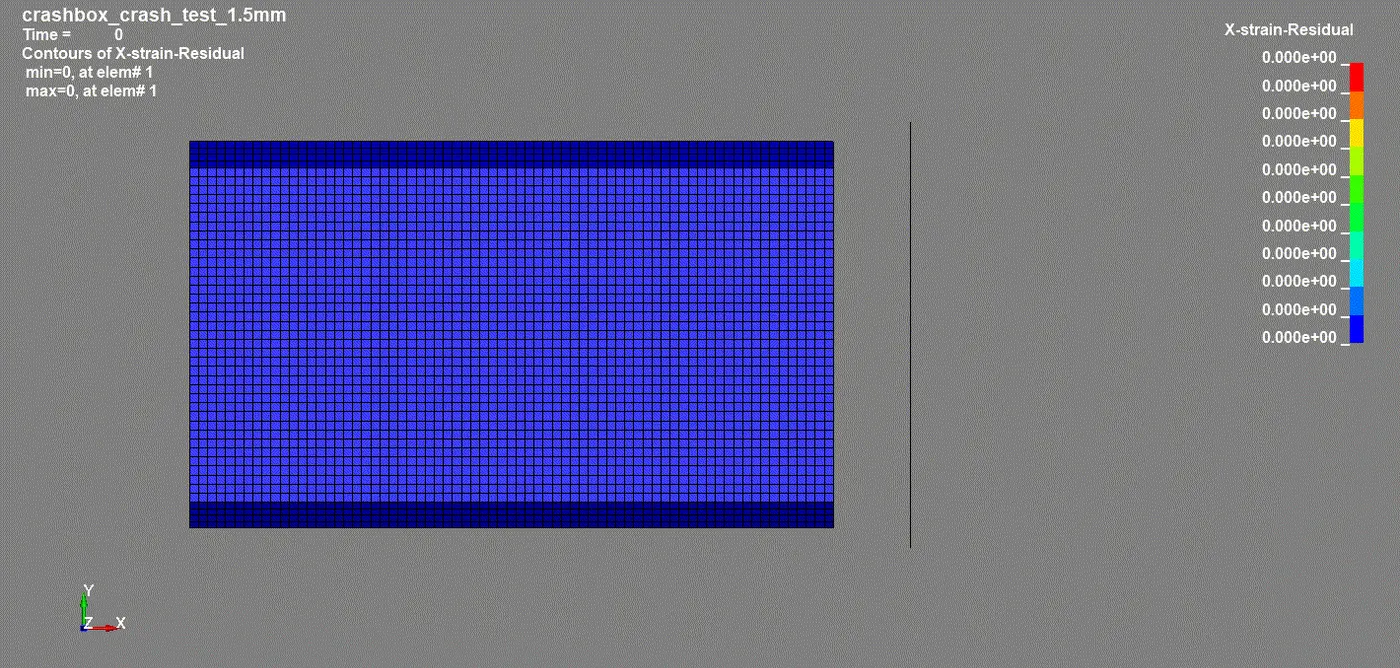
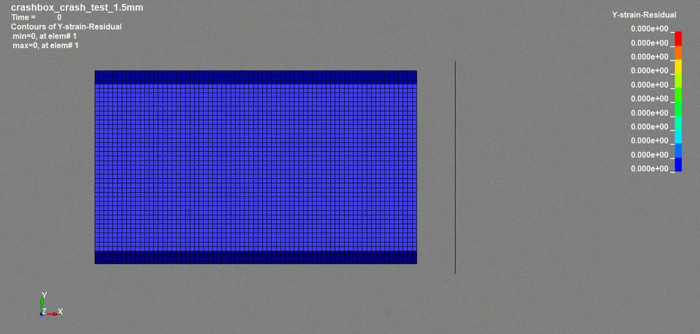
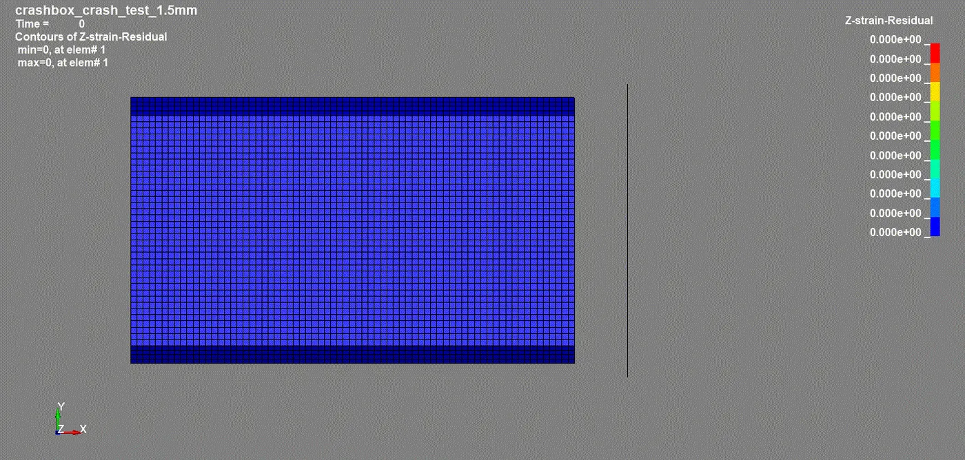
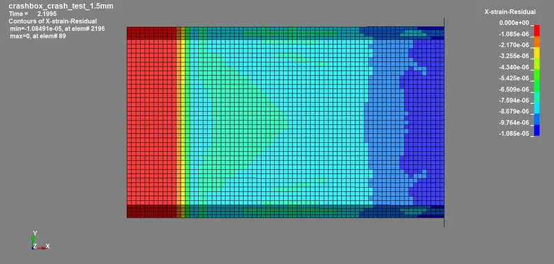
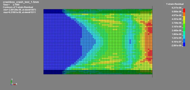
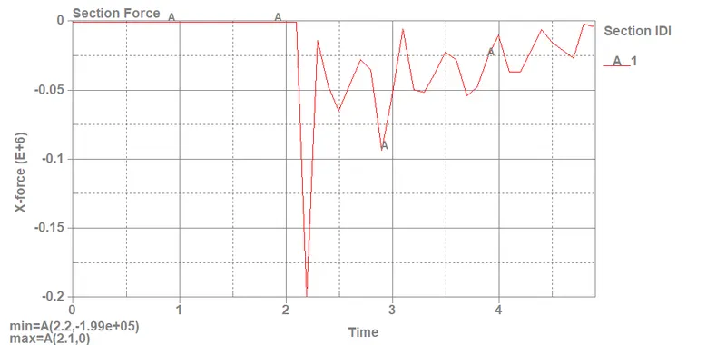
Residual strains in X, Y, and Z coordinates for 1.5mm thickness crash box
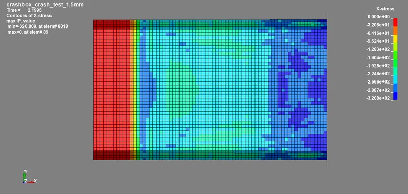
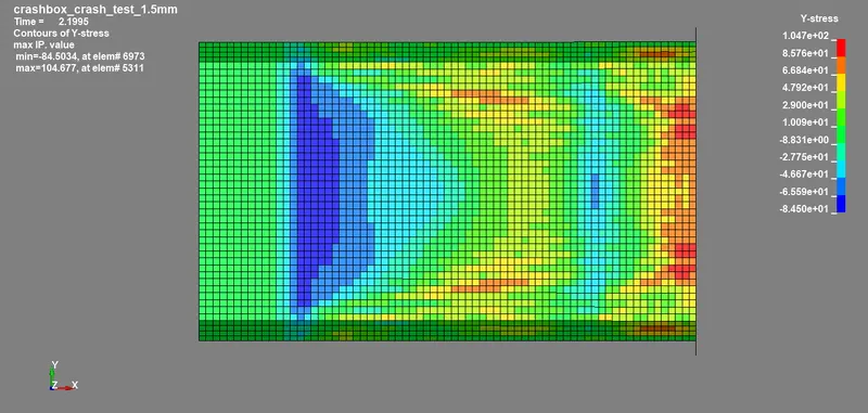
- The maximum directional stress and strain along the length of the 1.5mm thickness crash box are displayed below in the given images w.r.t the particular elements.
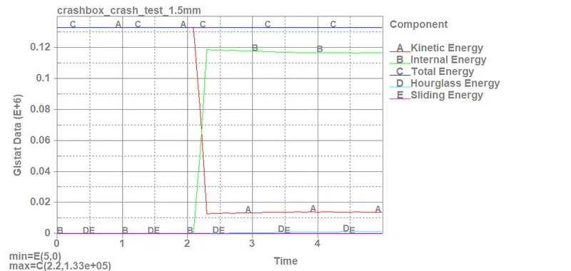
Glstat energies for 1.5mm thickness crash box as per prescribed data is given as:
- Maximum Kinetic energy, K.E = 1.35e+05 gm mm2/ms2
-
Maximum Internal Energy, U = 1.2e+05 gm mm2/ms2
-
Total Energy, E = 1.35e+05 gm mm2/ms2
-
Maximum Hourglass Energy, HG = 1.63e+03 gm mm2/ms2
-
Sliding Energy, SE = 0 gm mm2/ms2 (Positive value means the contact between rigid wall and crash box was successful)
Comparison of 1.5mm and 1.2mm thickness crash boxes
Effective stresses (Von-Mises) for 1.2mm and 1.5mm thickness crash boxes
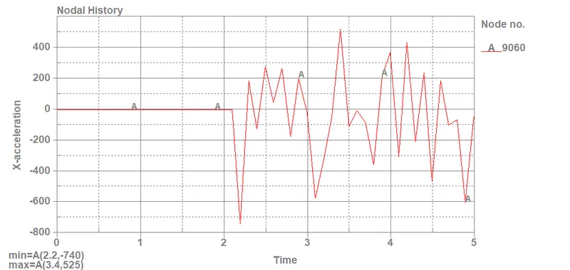
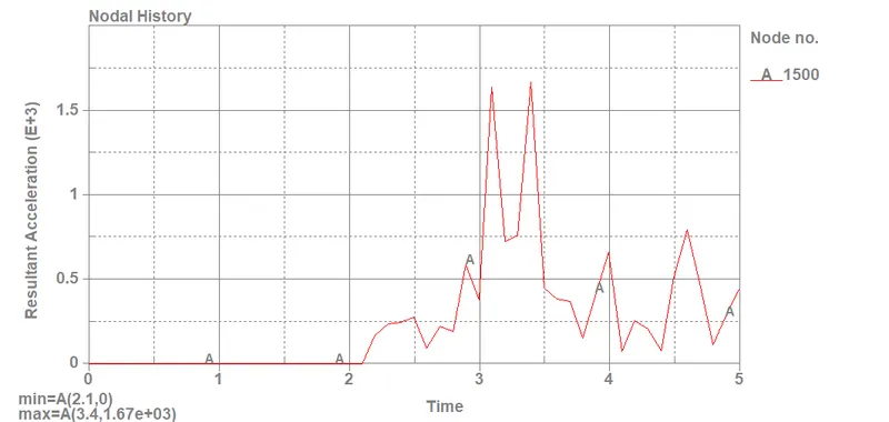
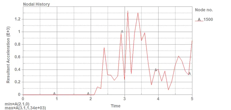
Resultant accelerations for 1.2mm and 1.5mm thickness crash boxes
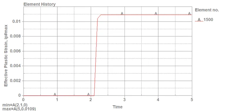
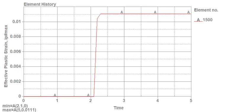
Effective plastic strains for 1.2mm and 1.5mm thickness crash boxes
CONCLUSION:
- The acceleration generated by the 1.2mm thickness box is more than the 1.5mm thickness box while as plastic strain developed in the latter is more than the former.
- The stresses obtained in both types of boxes are quite similar with a 0.1 difference only in the value. Hence we can determine that a bigger thickness produces larger stress and strains than a smaller one.
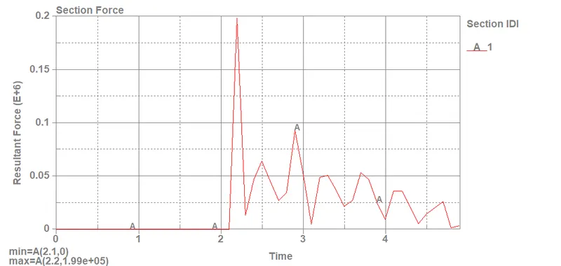
- Nevertheless, the resultant forces and global statistics and energies acquired for the 1.5mm thickness crash box are also more than the 1.2mm thickness crash box