Project 1 - 2D meshing on the instrumental Panel
2D-MESHING ON THE INSTRUMENTAL PANEL OF THE CAR USING ANSA
INTRODUCTION
A dashboard is a configuration tool located inside the center console of a car or small airplane. It is also referred to as a dash, instrument panel (IP), or fascia. It often rests prominently in front of the driver (or pilot), showcasing the vehicle's operating controls and instrumentation.
The contemporary dashboard may contain a wide variety of gauges, controls, information, climate control, and entertainment systems, whereas the original dashboard had a variety of simple controls (such as the steering wheel) and instruments to display speed, fuel level, and oil pressure.
The speedometer, tachometer, odometer, fuel gauge, engine coolant temperature gauge, turn indicators, gearshift position indicator, seat belt warning light, parking brake warning light, and engine fault lights are common components of modern dashboards. Gauges that show the amount of air pressure in the braking system are also included in heavy vehicles with air brakes, such as trucks and buses.
Since the aftermarket usage of dash kits has increased, several automakers have made the step to provide their dashboards with more stylish accents. The Chevrolet Sonic, which provides both external (such as a unique graphics package) and interior aesthetic changes, is a notable example of this. [8] Numerous businesses provide domed polyurethane or vinyl appliqué dash trim accent kits or "dash kits" in addition to OEM dashboard trim and enhancements.
Fuel-economy meters have been added by manufacturers including BMW, Honda, Toyota, and Mercedes-Benz to various instrument clusters, indicating fuel efficiency in real-time. However, these gauges were only seen in luxury cars and later hybrids.
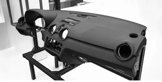
Figure 1 Instrumental panel or dashboard of the car
AIM
For the given component, check for the geometrical errors and mesh with the given element Quality criteria. After meshing the component the thickness has to be assigned.
|
S.No |
Quality Criteria |
Value |
|
1 |
Target/Average length |
4 |
|
2 |
Minimum Length |
2 |
|
3 |
Maximum Length |
6 |
|
4 |
Aspect |
3 |
|
5 |
Warpage |
15 |
|
6 |
Skewness |
45 |
|
7 |
Jacobian |
0.7 |
|
8 |
Minimum Quad Angle |
45 |
|
9 |
Maximum Quad Angle |
135 |
|
10 |
Minimum Tria Angle |
30 |
|
11 |
Maximum Tria Angle |
120 |
|
10 |
Tria Percentage |
15 |
PROCEDURE
The pre-processing stages of this project are divided sequentially as follows:
- In a single integrated environment, ANSA's comprehensive interdisciplinary CAE pre-processing tool offers all the capabilities required for full-model build-up, from CAD data to ready-to-run solver input files. So we first import the model using the open option in the Files drop-down icon of the menu bar. The file required for processing is in .ANSA format and the status bar below show the processing status of uploading a file or any other operation. After importing we pan rotate and zoom the model and analyze its configuration to get a better understanding of the physics applied to it. Without further ado, we will check geometric errors by using the Geometric checks option in the Tools bar. So we came across a lot of geometrical distortions whiz unchecked faces, needle faces, and empty faces. We manually fixed intricate portions of the whole CAD geometry and the rest by the auto method. Also, we used Faces>Topo in the Topo module to stitch all faces together of the whole model.
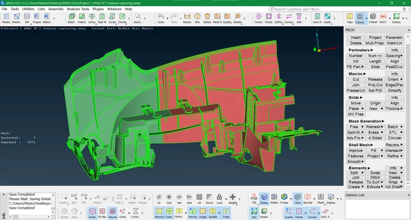
Figure 2 Orginal geometry imported into ANSA
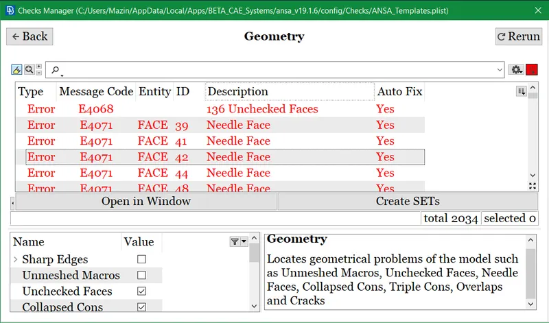
Figure 3 Geometric errors found by the Checks manager on the parent geometry
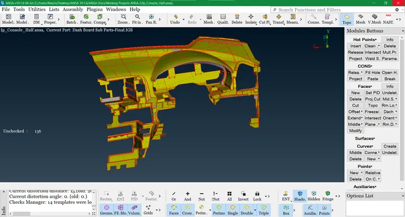
Figure 4 Unstitched model prior to topo clean up
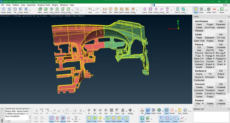
Figure 5 Model post topo clean up
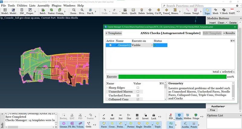
Figure 6 All geometrical errors are eliminated by auto and manual methods
- Nevertheless, we advance towards another phase which is meshing but prior to that, we need to do mesh prep. First, we will alter the cons resolution with respect to the given target length by using Perimeters>Length in the Classic mesh module. However, we will input meshing parameters and quality criteria parameters provided in the prescribed data as well. Since the component has a varying thickness and is very huge so we opt for the casting process in order to save time. Align manager used to give a proper definition and alignment to faces and perimeters which is a pretty handy technique to complete the pre-processing with better results. Both options are in Faces>Middle surface of Topo deck and therefore we divide the component into two PIDs in order to attain Casting results quickly without any software crashes. In the casting process, we obtain FE only and no middle surface like manual methods and we can manually fix damaged FE by using Classic mesh deck tools and align manager.
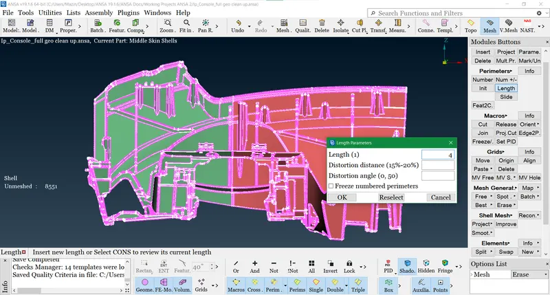
Figure-7 Modifying cons resolution by ascribed target length
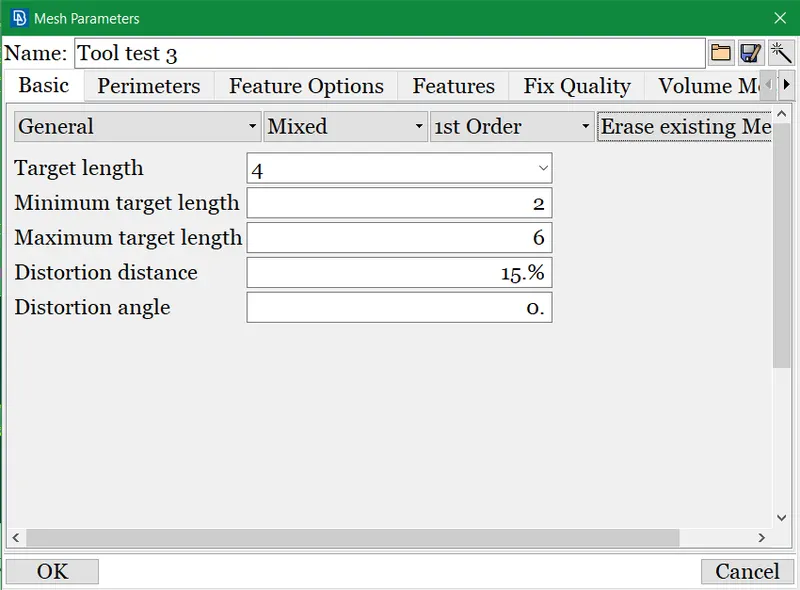
Figure 8 Inserting mesh parameters
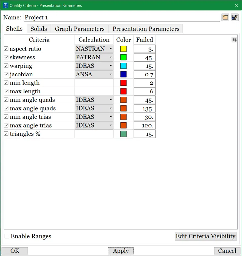
Figure 9 Inserting Quality criteria parameters
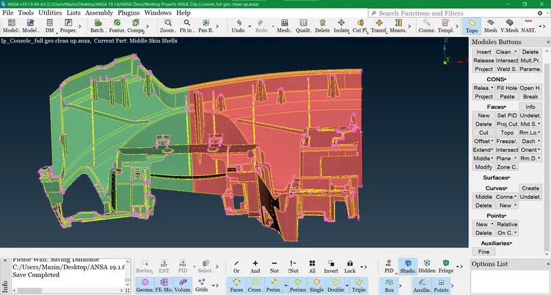
Figure 10 Use zone cut and divide the model into 2 parts to ease the casting process
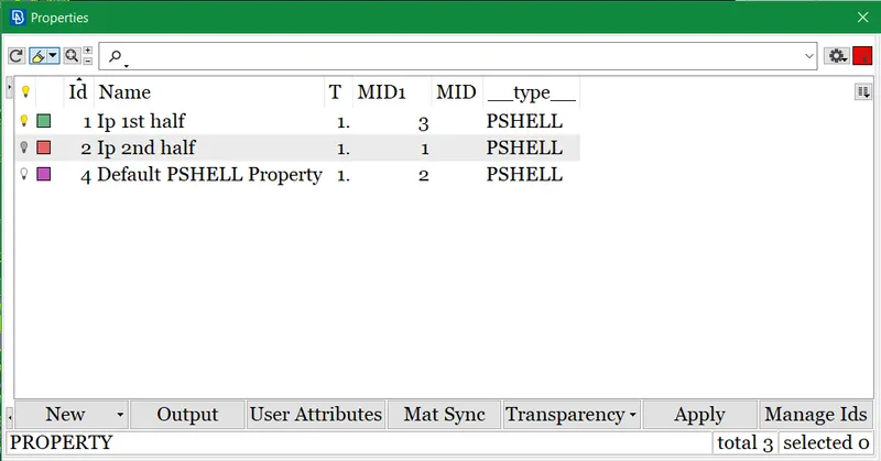
Figure 11 PIDs set for two divided parts to facilitate processing
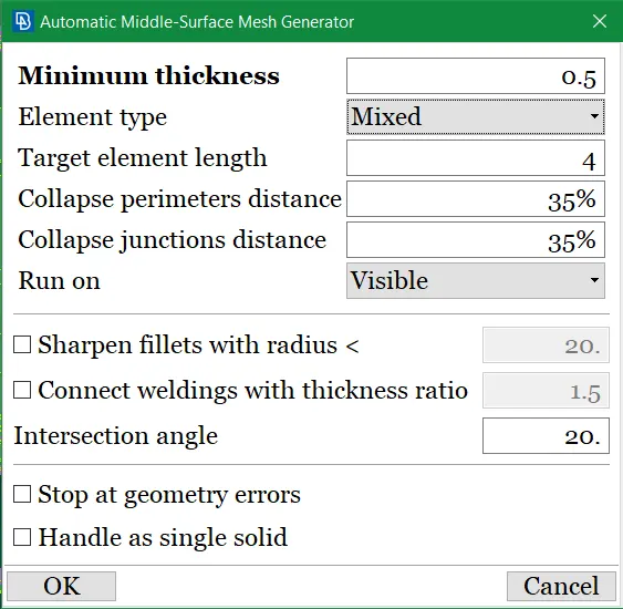
Figure 12 Using the casting process to develop FE quickly
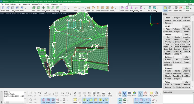
Figure 13 FE generated by Casting for the first half of the instrumental panel model
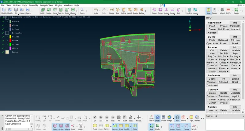
Figure 14 FE generated by Casting for the 2nd half of the instrumental panel model
- Henceforth we developed FE of the mentioned 2 PIDs of the model so now our primary focus is feature capturing. As the elements have no associativity with the faces of the component so we need to re-create or produce elements only connected with the rest of the Finite elements. After keen observation, we noticed some damaged features mostly dog houses and some ribs because ANSA is not able to comprehend its configuration. So without further ado, we progress by rectifying these damaged Finite elements using align manager and Classic mesh deck tools like
Shell Mesh> Fill
Elements> New
Elements>Del
Grids>Align
Shell Mesh>Project
Grids>Paste
Macros>Cut/Join
Also, we need to clear all empty areas and perimeters in align manager and give them a proper definition to obtain better mesh flow and aligned feature capturing.
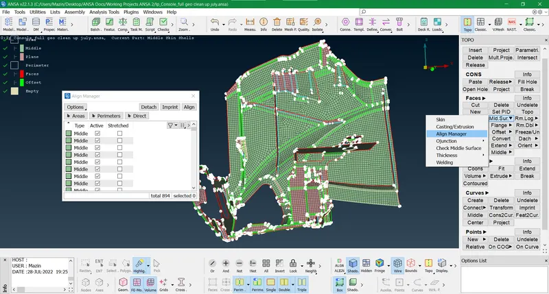
Figure 15 Using align manager to enhance the geometrical capturing and mesh flow
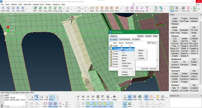
Figure 17 Providing definitions to empty faces/Areas
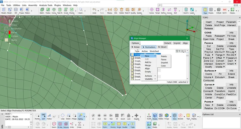
Figure 18 Assigning definition to empty perimeters
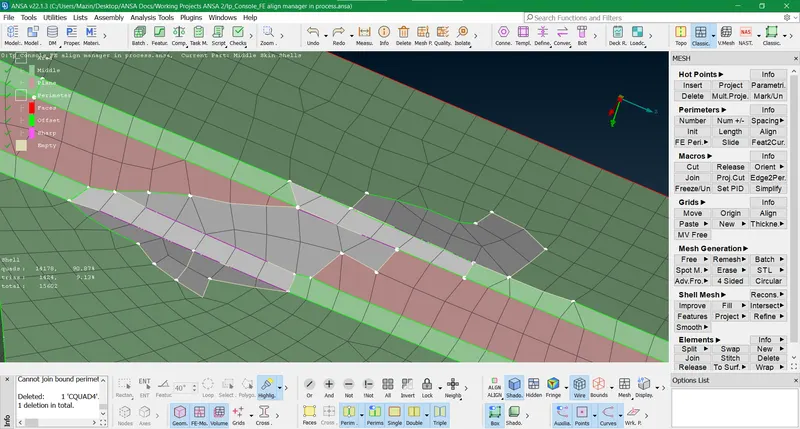
Figure 19 Filling up damaged FE area near a damaged feature
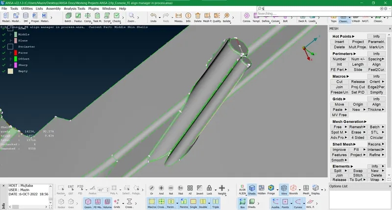
Figure 20 Original feature that is damaged post casting
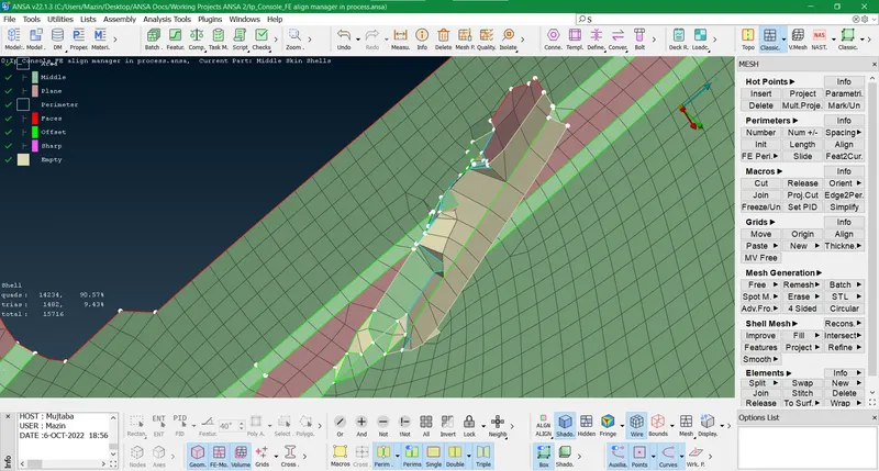
Figure 21 FE of damaged feature acquired post casting
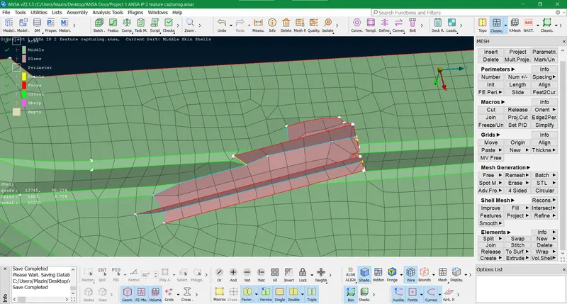
Figure 22 Damaged feature corrected and aligned with its base surface
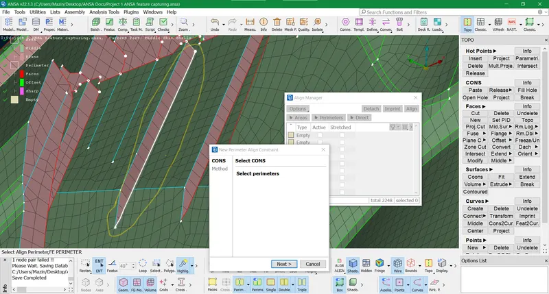
Figure 23 Allocating perimeter definition to empty perimeters by face option
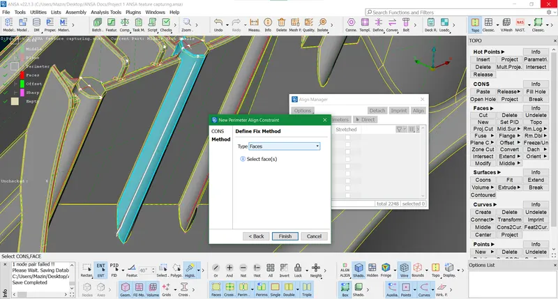
Figure 24 Selecting the faces option for the perimeter definition to get proper alignment
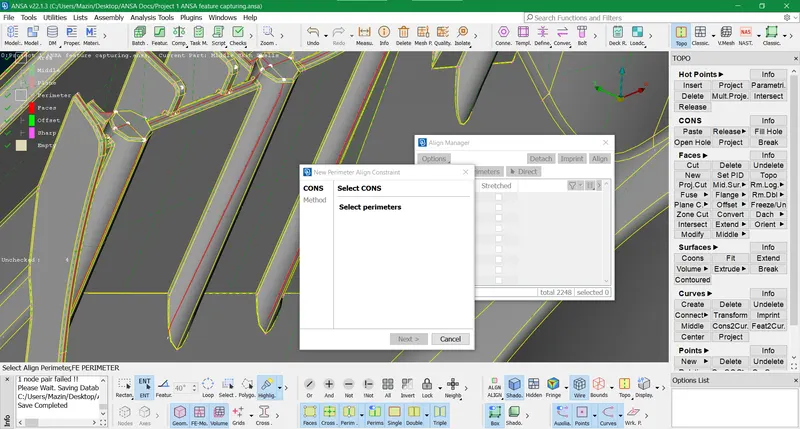
Figure 25 After giving a definition it is aligned w.r.t to the face connected to it
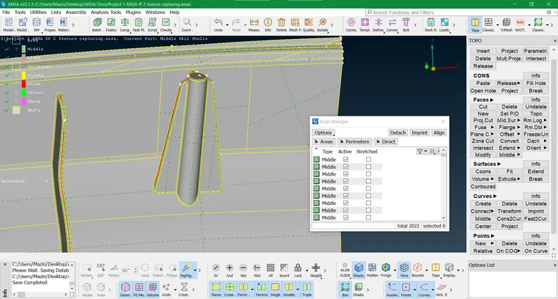
Figure 26 Geometry of Orginal dog house feature
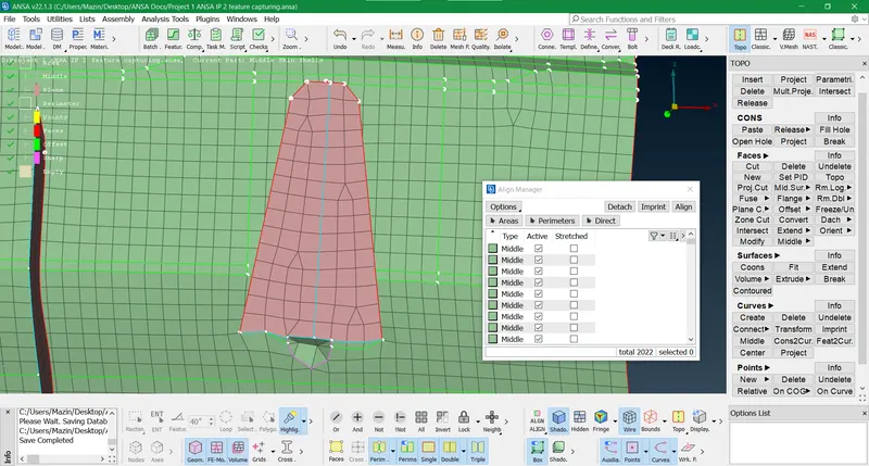
Figure 27 FE of dog house feature generated by auto mid-mesh method with base surface distorted
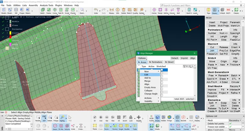
Figure 28 After aligning it by giving a proper middle definition for areas
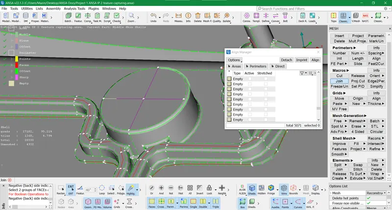
Figure 29 For this cylindrical dog house feature we extract its FE likewise by intersecting it into two halves
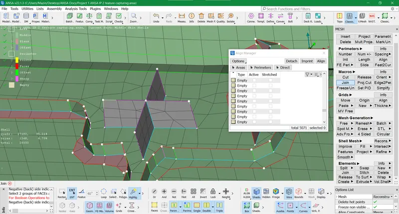
Figure 30 FE generated for Cylindrical feature after a series of operations
- Once the primary objective is achieved i.e. feature capturing and alignment, we advance toward the secondary and last stage which is fixing elemental quality errors. We use a lot of tools to modify or redevelop the mesh to develop a good quality FE component in the Classic mesh deck whiz.
Shell Mesh>Improve/Reconstruct
Shell Mesh>Smooth
Grids>Paste
Elements>Split
Elements>Swap
Elements>Join
Grids>Align
Grids>MV Free
Grids> Move
In some of the areas like near 2 triple cons and at some outer edges or perimeters the elements will likely fail to elemental errors w.r.t quality parameters that can be ignored.
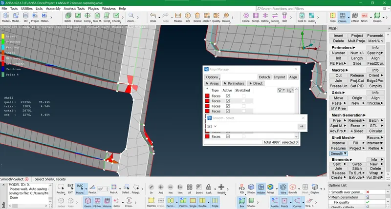
Figure 31 Fixing failed elements by classic and shell mesh deck tools
- Finally, after clearing elemental errors for the whole model we assigned thickness for each feature or simple face by auto thickness technique in the Classic mesh deck. We choose Grids>Thickness>Convert pathway to change nodes to property i.e a number of PIDs w.r.t the thickness of parent geometry. ANSA is not able to figure out the thickness of some features so we manually update them by creating new PIDs with Set PID in the Faces menu box of the Topo deck. Lastly, we draw the shell as a solid for the modified FE and evaluate it finally by comparing it with parent geometry.
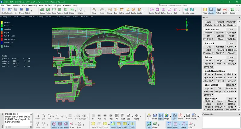
Figure 32 Model after cleaning quality errors except at certain areas which hindered the feature capturing
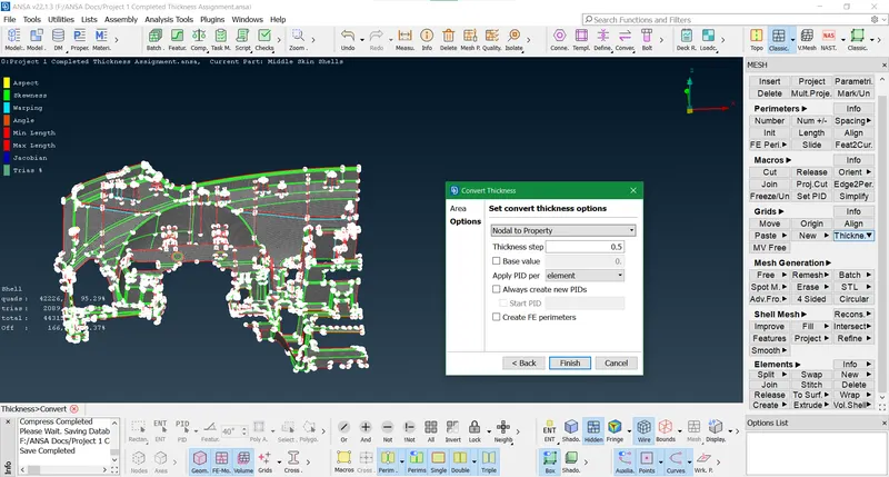
Figure 33 Auto thickness assignment for the whole model
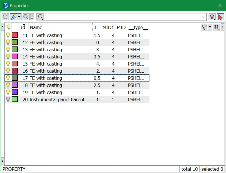
Figure 34 PIDS created automatically post auto thickness operation
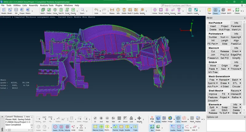
Figure 35 Final image of instrumental panel model after attributing thickness to it
LEARNING OUTCOMES
- This project provided a better insight into using ANSA for bigger components with less processing time.
- It gave us an opportunity to explore new tools like Align manager and use them effectively with the casting method to extract FE for the whole component automatically.
- We developed a better hold on extracting mid-surface or FE from parent geometry for intricate features and sections of any component or entity.
- The align manager with a blend of basic mesh tools saves time for clearing quality errors and refinement of the overall mesh.
CONCLUSION
- In this project, we pursued with automatic middle surface mesh generator or casting method to obtain a mesh within a short time as the geometry was huge.
- The feature capturing for many dog houses and ribs was distorted and damaged so it was manually fixed by certain basic topo and classic mesh tools.
- The meshing algorithm was average as compared to manual methods so it was also cleared by basic mesh tools.
- The tria concentration was minimized to a large extent in this model and quality was compromised a few areas in order to allow precise feature capturing.