Bird Strike - Project - 2
BIRD STRIKE ANALYSIS USING LS-DYNA
INTRODUCTION
An aviation engine, often known as an aero engine, is the power source for an aircraft's propulsion system. There are 5 main types of aircraft jet engines. Each has its benefits, drawbacks, and best use cases.
- TURBOPROP ENGINE
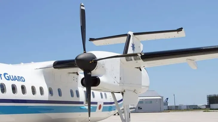
The turboprop engine is a turbojet engine that connects to the aircraft propeller via a gearing system. An aircraft's gearbox includes a turbojet that spins the shaft connecting to it. The gearbox slows the spinning shafts so that the gear may be connected to the propeller. The turboprop engine consists of a combustion chamber that includes pressurised air and gas, a turbine, and a compressor that drives the turbine.
- TURBOJET ENGINE
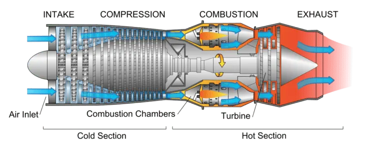
The principle of a turbojet aircraft engine is straightforward. It involves drawing air from the engine's back and compressing it in the compressor. However, the fuel must be introduced to the combustion chamber and consumed in order to elevate the temperature of the fluid combination to around 1000 degrees. These are reaction aeroplane engines that inflate gases to allow the plane to push against atmospheric pressure. It draws in the air before compressing or squeezing it to let an aeroplane fly. Air is passed through the turbojet's intake, compressor, turbine, combustion chamber, and exhaust.
- TURBOSHAFT ENGINE
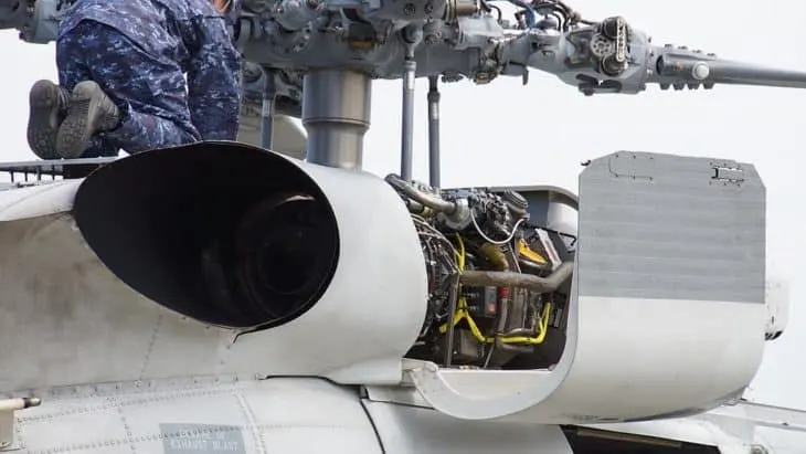
The turboshaft engine is a type of gas-powered turbine that functions similarly to a turboprop engine. Turboshaft engines, unlike turboprop engines, do not drive a propeller. It is instead employed in helicopters to power the rotor. Turboshaft engines propel themselves by converting high-speed gases into mechanical power to operate accessories such as the turbine and compressor. The shaft coupled to the turboshaft engine, like the turboprop engine, powers both the aircraft propeller and the rotor blade gearbox of a helicopter. The reduction gearbox is used to push an aeroplane forward.
- TURBOFAN ENGINE
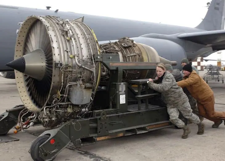
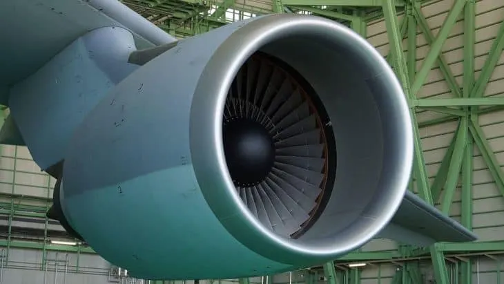
A huge fan at the front of turbofan jet engines is used to draw in air. Most of the airflow around the outside of a turbofan jet engine to provide the plane more push even at low speeds and to keep it quiet. The majority of today's airliners are powered by turbofan jet engines. All of the air that enters a turbofan jet engine's intake passes via the generator that creates the hot air. A turbine, combustion chamber, and compressor are all part of this generator. Only a small portion of the air passing through the turbofan engine reaches the combustion chamber.
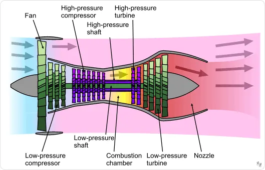
The turbofan aviation engine is a more powerful variant of the turboprop and turbojet engines. It operates similarly to a turbojet engine, except it has a ducted fan in front. The fan cools the engine, adds power, and reduces noise from the aircraft engine.
- RAMJET ENGINE
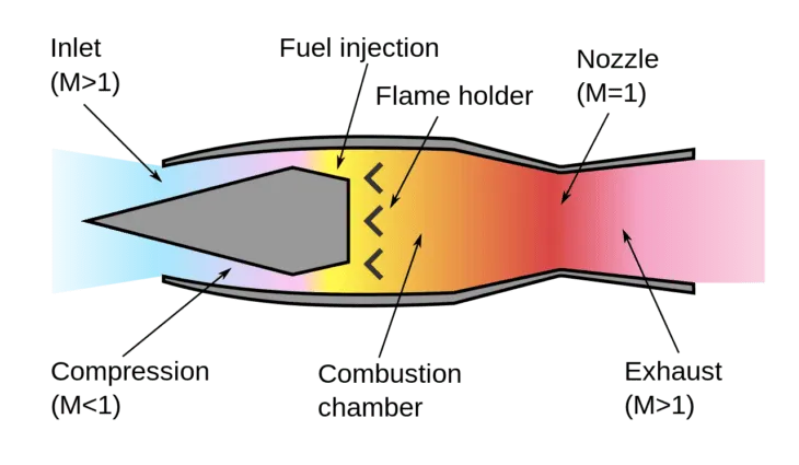
These are the lightest forms of aeroplane engines, having no moving parts. The aircraft's speed is crucial for driving air into the engine. Ramjets work similarly to turbojets but without moving elements. However, the fact that the compression ratio of a ramjet engine relies on the speed of the aircraft limits its use. Unlike conventional engines, the ramjet creates minimal push below the speed of sound rather than static thrust. That implies a ramjet-powered aircraft requires help during taking off, which might come in the shape of another aircraft. The ramjet engine has been utilised in spacecraft and a variety of guided-missile systems.
ABSTRACT:
- BIRD STRIKE: A bird strike is described as a collision between a bird and an aircraft in flight, or on a takeoff or landing roll. Other wildlife strikes, such as those involving bats or ground animals, are frequently included in the definition. Bird strikes are prevalent and can pose a serious hazard to aviation safety. Smaller aircraft may sustain considerable structural damage, and all aircraft, particularly jet-engined aircraft, are vulnerable to loss of power due to bird ingestion into engine air intakes. As a result, a number of deadly accidents have occurred. The kind of aircraft damage caused by bird attacks that is serious enough to pose a high danger to continued safe flying varies according to aircraft size. Small, propeller-driven aircraft are more susceptible to sustaining structural damage from attacks, such as penetration of flight deck windscreens or damage to control surfaces or the empennage.
Windscreen penetration has resulted in injuries to pilots and other passengers in certain circumstances, particularly in smaller fixed-wing aircraft and helicopters, and has sometimes resulted in the loss of control. Although uncommon, a higher altitude bird hit to a pressurised aircraft might cause structural damage to the aircraft hull, leading to fast depressurisation. Impact damage to extended landing gear components in flight is a more likely source of trouble, which can create enough failure of brakes or nose gear steering systems to cause directional control problems during a subsequent landing roll.
- NON-LINEAR TRANSIENT DYNAMIC ANALYSIS: A non-linear transient dynamic analysis may simulate time-dependent issues while taking into account any or all of the three categories of non-linearities: material non-linearity, geometric non-linearity, and constraint non-linearity. A non-linear transient analysis should be utilised if the relative effects of inertia, damping, and transient loads are considered in the system. Models that encounter buckling or other unstable loading circumstances may frequently converge better in a non-linear transient analysis due to inertia effects that keep the model stable. Damping is frequently employed in nonlinear transient dynamic analyses. This can be described as either a global damping coefficient, which applies the same value to all elements of the model, or as specific damping values applied to those components that share the same material, which is known as material-based damping. The latter is more commonly utilised since it provides the user with greater freedom. A drop test simulation is an example of when a non-linear transient dynamic analysis is useful. The plastic behaviour of the material, as well as non-linear contact and significant deformation, must be considered.
- The bird, the target, and their dynamic impact interaction are the three main components of the bird strike problem. The biggest technical drawback of utilising actual birds in experiments is the issue of repeatability of results, which is caused by the non-homogeneity of the bird material. Because of this non-repeatability, validating test results is extremely difficult. Several studies have investigated the use of wax, foam, emulsions, and gelatin as alternative bird materials.
- Full-scale bird hit tests are required to quantify the degree of damage following a bird impact and to determine the critical dynamic failure location. In this report, explicit finite element analysis is used to estimate the deformation pattern of the bird, and numerical results are compared. The turbofan engine is tested in this approach as discussed earlier. Finally, recommendations regarding the optimal strategy are provided.
REQUIREMENTS:
- Follow a consistent numbering approach of 100000+ for nodes, 500000+ for elements, and 1000+ for the parts. All other keywords should be numbered between 10000-19999 while following a range for each one. This guideline that the student is following should be included in the final submission
- The bird, casing, and blades should be in different input files and there should be one main file referencing all the input files. The main file should contain only references. Control cards and boundary conditions should be there in another separate file. The reference "include" path should be such that the folder can be copied anywhere and it is able to correctly reference all the files and run the simulation.
AIM :
-
The final submission must include the input file, animation, and a report.
-
Since this is a quite difficult and involved project, students are advised to log their debugging process and include it in the report. The log is a description of the solution process and challenges encountered along the way.
-
The numbering approach should be described in the report.
-
Usage of mass scaling is encouraged and trial and error should be included in the report as well.
EXPLANATION:
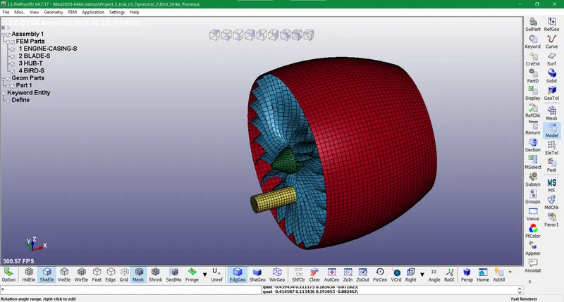
- The word "birdstrike" refers to a collision between a bird and an aircraft, as defined by aeronautical regulations. The windscreen, nacelles, wing leading edge, and compressor blade are all front-facing components. In this Project, an analysis is done on the turbofan engine model that comprises 4 parts whiz Engine casing, fan blades, hub and bird specimen. This project is a non-linear transient dynamic problem that is solved using Explicit analysis. The keyword tool is used from the side panel of LS-dyna to create appropriate cards for solving and post-processing.
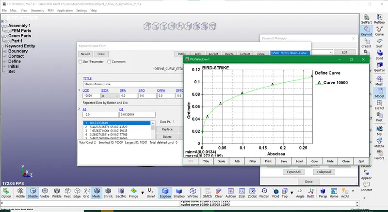
- In the 1980s, Rolls-Royce pioneered the hollow, titanium wide-chord fan blade for aerodynamic efficiency and foreign object damage resistance in the RB211 and Trent. In 1995, GE Aviation developed carbon fibre composite fan blades on the GE90, which are now made using a carbon-fibre tape-layer technique. Safran, a GE partner, collaborated with Albany Composites to create 3D weaving technology for the CFM56 and CFM LEAP engines. The material and load curve(Stress-Strain) for blades is given so the data is copied to the Bird-strike keyword file. The unit system used for this project is (kg, mm, ms, KN, GPa, KN-mm) of all the parameters involved in each card. This is Material Type 24, an elastoplastic material with arbitrary stress as a function of strain curve and arbitrary strain rate dependency. Failure can be specified based on a plastic strain or a minimum time step size. The Mat(024) card is used for blades and hub with specific values. The material used in blades is Aluminium for this type of analysis.
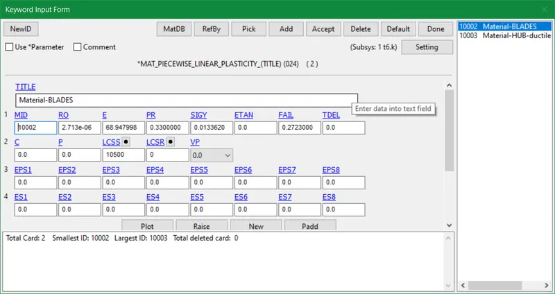
- Aluminium is a metallic elastoplastic material having an elastic zone followed by a plastic deformation phase and no strain hardening behaviour. The curve inputted in the Define>Curve keyword depicts the same behaviour.
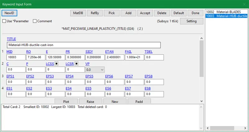
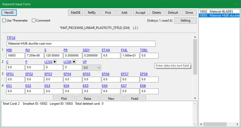
- The material chosen for Hub is ductile cast iron and the computed values for the MAt(024)card are described as follows:
Material of Hub:
Density, (RO) = 7.250E-06 Kg/mm^3
Young's Modulus (E) = 120.5 GPa
Poisons Ratio (PR) = 0.30
Yield Stress (sY) = 0.200 GPa = 0.200 Kg mm/ms^2
Tangent Modulus (ETAN) = 2% of Young's Modulus = (2/100) x 120.5 = 2.4 GPa
- Due to the spherical (round) graphite distributions in its molecular structure, ductile cast iron is a type of metal material with significant fatigue, impact, and corrosion resistance.
Ductile cast iron contains much more carbon (3.0% - 3.9%) than other types of iron, such as cast steel, which typically contains 0.08% - 0.60% carbon. This distinction accounts for its distinct corrosion resistance.
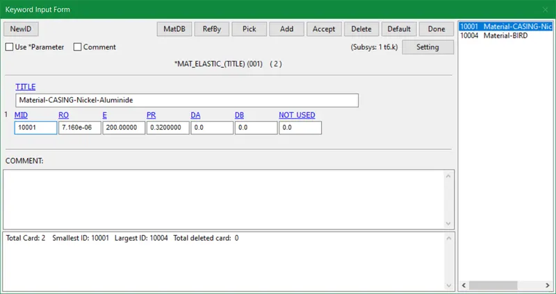
- Now we use Mat(01) i.e. Elastic card for Bird and Engine Casing. This is an isotropic hypoelastic material that is available in LS-DYNA for beam, shell, and solid components. This material's specialization enables fluid modelling.
- Since the fan casing is the heaviest portion of the engine, comparatively light materials such as titanium, aluminium, and nickel aluminide are utilized for it. It is disclosed as a nickel-based alloy suited for casting gas turbine components with a lower density and basic heat-treating method while attaining improved strength. Multiple alloy embodiments are given, each capable of producing both directionally-solidified and equiaxed castings.
Material of Engine Casing:
Density, (RO) = 7.160E-06 Kg/mm^3
Young's Modulus (E) = 200 GPa
Poisons Ratio (PR) = 0.32
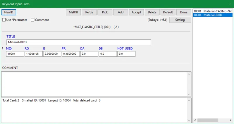
- The assumptions are made for bird specimen and the computed values are as follows:
Material of Bird:
Density, (RO) = 1.000E-06 Kg/mm^3
Young's Modulus (E) = 2 GPa
Poisons Ratio (PR) = 0.48
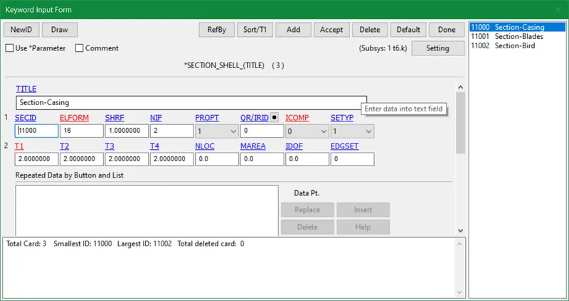
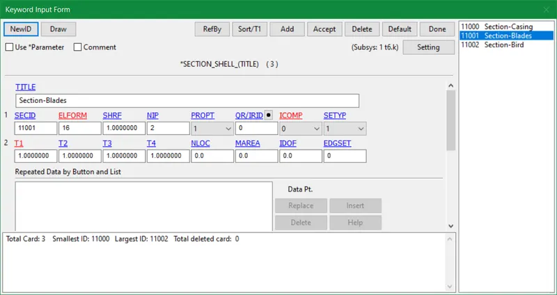
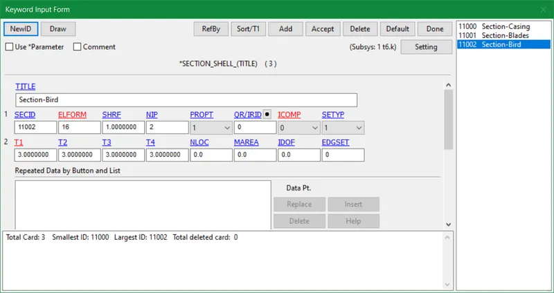
- The section_shell card is inserted as it defines section properties for shell(2D) elements. The element formulation 16 is used which means: Fully integrated shell element (very fast). The thicknesses are assumed as shown below for all shell element parts.
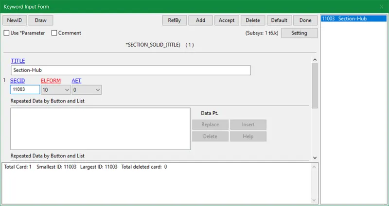
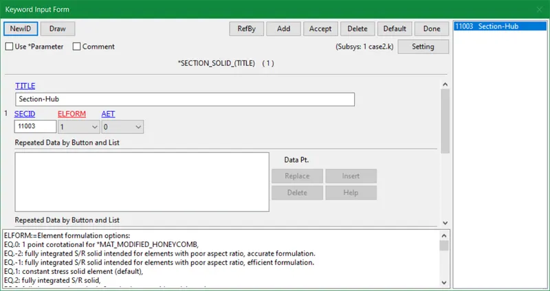
- The hub part is composed of solid elements (3D) so the Section_solid card is inserted that defines section properties for solid continuum and fluid elements. Elform 10: 1 point tetrahedron is used for hub elements.
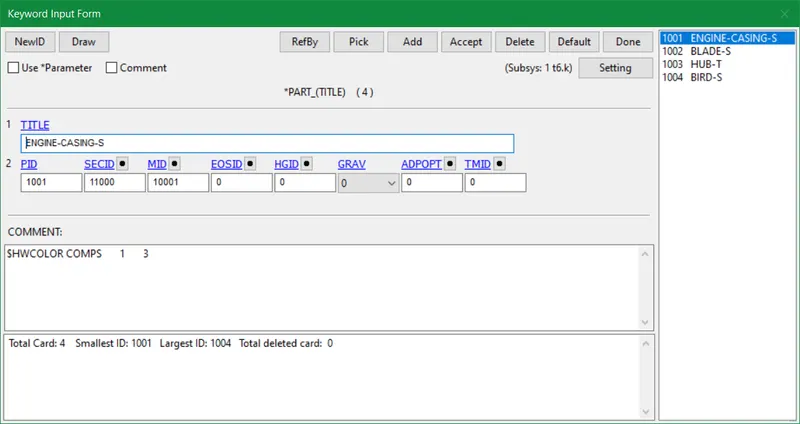
- The Section IDs and Material IDs as established earlier are registered in the part cards respectively.
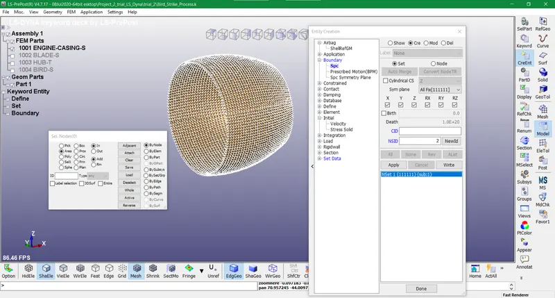
- The SPC set is created for Engine casing and the motion of all translational and rotational DOFs is constrained.
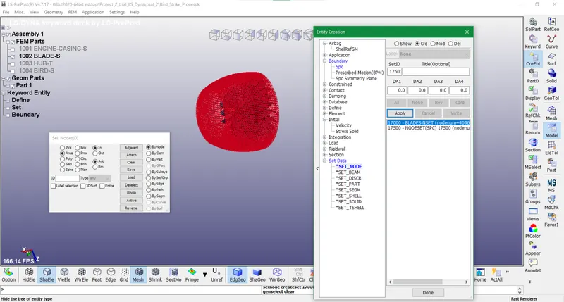
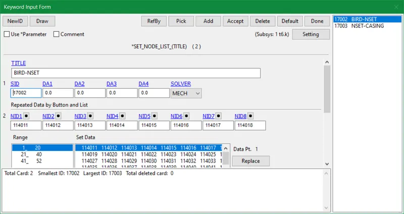
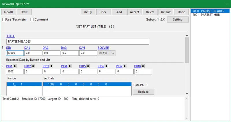
- Node sets and part sets are developed using the entity creation tool for all parts consequently.
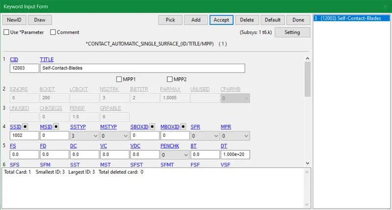
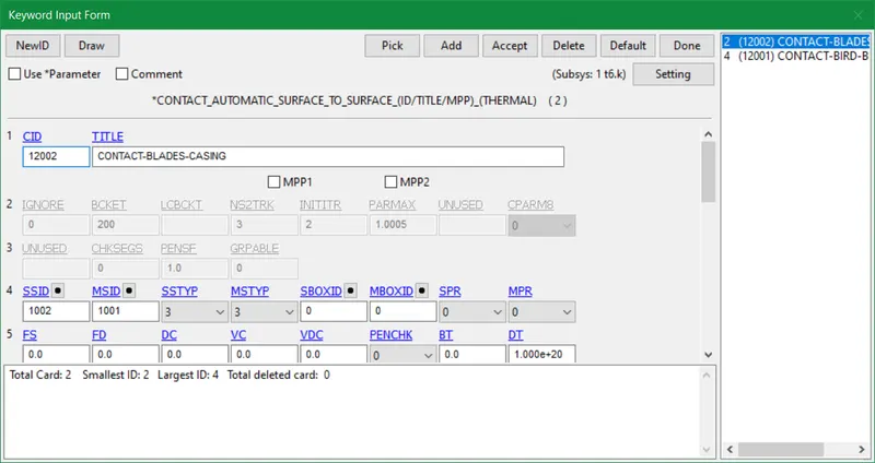
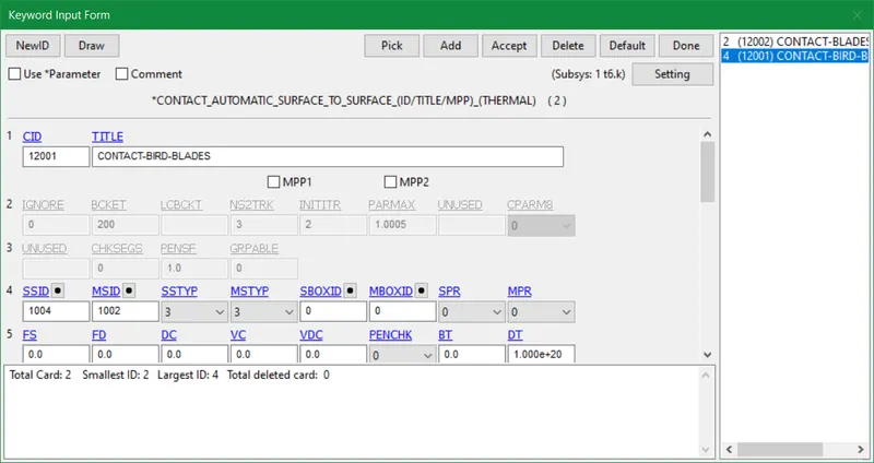
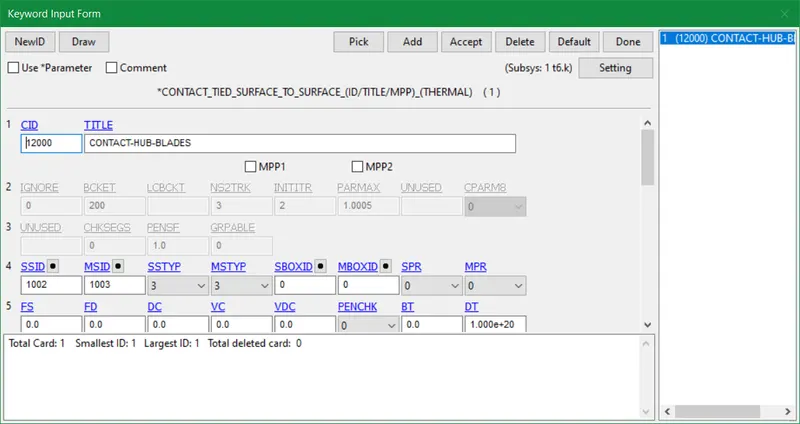
- Contact facilitates interaction between two defined component surfaces. Contact normals are the recognizable orientations of contact surfaces. If you have a combination of rigid and deformable bodies, the rigid should be the master and the deformable should be the slave. A contact in LS-DYNA is defined by identifying (through parts, part sets, segment sets, and/or node sets) which places are to be examined for potential slave node penetration through a master segment. The Automatic_single surface and Automatic_surface_to_surface contacts are employed for shell components in this model. The Tied_surface_to_surface contact is used for solid components or solid and shell components. In tied contact types, the slave nodes are constrained to move with the master surface. The relevant part IDs are chosen for each contact as slave and master in all three contacts displayed below.
- Master= 0, Slave= Blades (12003)
- Master= Engine Casing, Slave= Blades (12002)
- Master= Blades, Slave= Bird (12001)
- Master= Hub, Slave= Blades (12000)
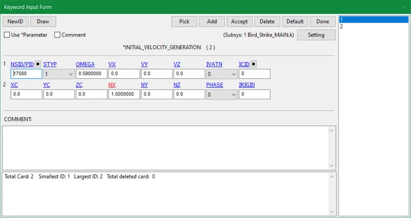
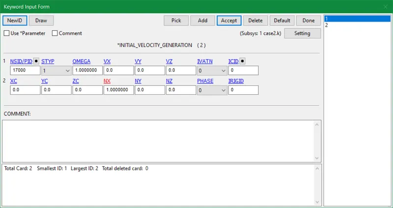
- Pratt & Whitney is a global leader in aircraft engine and auxiliary power unit design, manufacture, and servicing. According to them The fan of an IAE V2500 engine (that power the Airbus A320) spins at a maximum speed of 5,650 RPM. So we are assuming the realistic angular/rotational velocity to be 5650 r.p.m(Revolutions per minute). This velocity was proven to be most effective after doing several testing in this project. The initial_velocity_generation card is used that defines initial velocities for rotating and translating bodies. Since the axis of rotation is on the x-axis so we input cosine x as 1.
Angular Velocity, (omega) = 5650 r.p.m = (2 x pi x 5650)/60 = (2 X 3.1416 X 5650)/60 = 591.6 rad/s = 591.6/1000 = 0.59 rad/ms
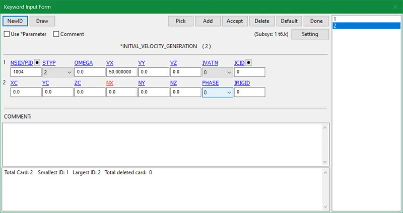
- The ideal velocity of a bird in a bird strike is taken as 275km/h. A 5 kg (11 lb) bird travelling at a relative velocity of 275 km/h (171 mph) has generally the same energy as a 100 kg (220 lb) weight dropped from a height of 15 meters (49 ft).
Translational Velocity of bird = 275 km/h = (275 x 1000)/60 x 60 = 76.3 m/s = 76.3 mm/ms
The translational Initial velocity of bird in this model = 180 km/h = (180 x 1000)/60 x 60 = 50 m/s = 50 x 1000/1000 = 50 mm/ms
- The keyword control cards are optional and can be used to override default settings. They can also enable solutions like mass scaling, adaptive meshing, and the implicit solver.
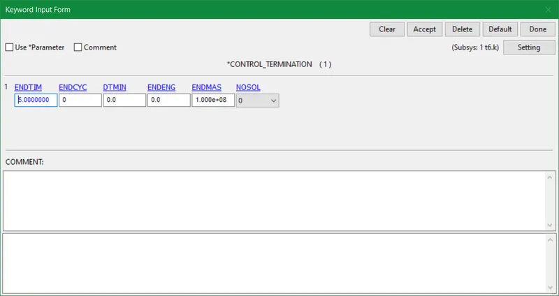
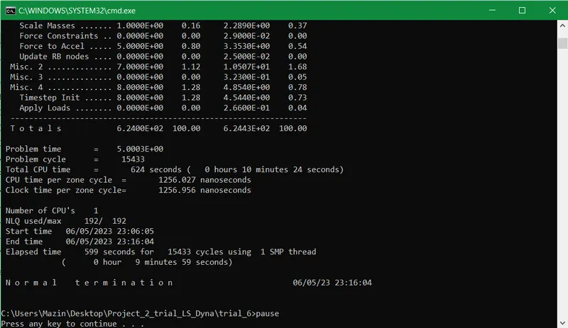
- The termination time of 5 ms is provided for the final simulation.
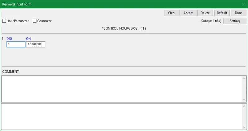
- The work done by the forces to combat the hourglass modes is referred to as hourglass energy. Hourglass (HG) modes of deformation are nonphysical, zero-energy modes of deformation that cause no strain and no stress. Only under-integrated (single integration point) solid, shell, and thick shell elements exhibit hourglass modes.
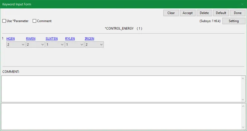
- Control_energy provide controls for energy dissipation options.
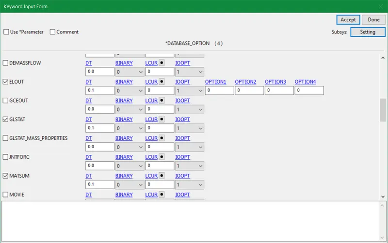
- The database definitions are optional, however, they are required in order to generate output files containing results data. The database definition cards in the input file are ordered absolutely arbitrarily. The database items used for this model are as follows:
ELOUT: Element data.
GLSTAT: Global statistics and energies
MATSUM: Part energies
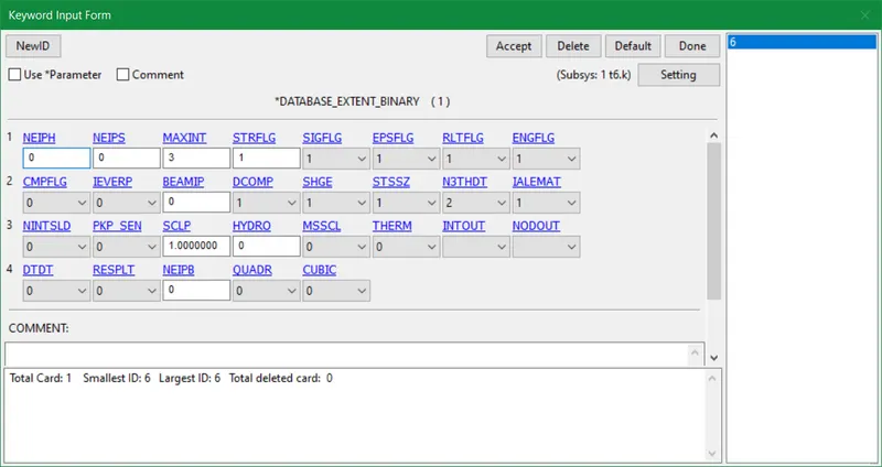
- Database_Extent_Binary controls the content of binary output databases d3plot, d3thdt, and d3part to some extent. The integration point strains along all coordinates are formulated by activating this card.
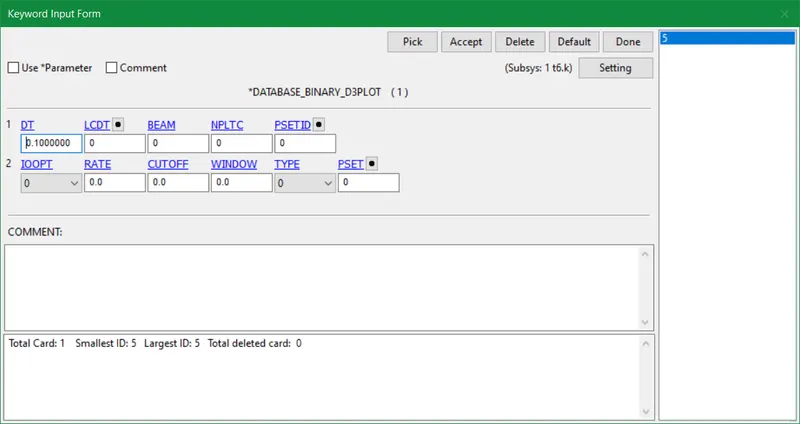
- Database_binary-d3plot outlines the database for the entire model. The output interval for d3plot is automatically set to one-twentieth of the termination time if *Database_binary_d3plot is not defined in the keyword deck.
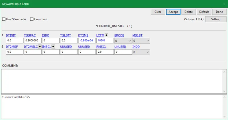
- Control-timestep uses a variety of variables to set the structural time step size.
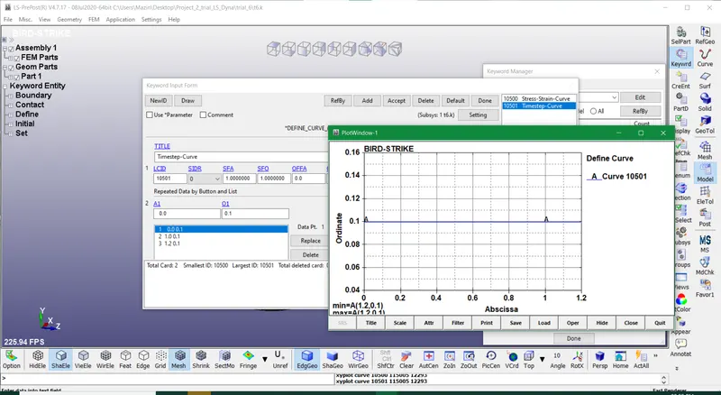
- Load curve ID with a maximum time step size restriction (optional). The maximum time step size allowed is specified as a function of time by this load curve.
- DTINIT determines the initial time step size. If it is put as 0 then LS-DYNA determines the initial step size.
- TSSFAC is the scale factor for the computed time step. It lies between 0.67-0.9 and beyond that it can lead to instabilities.
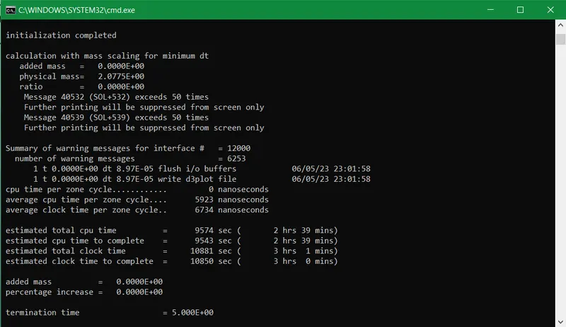
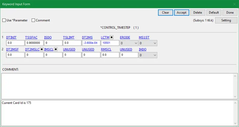
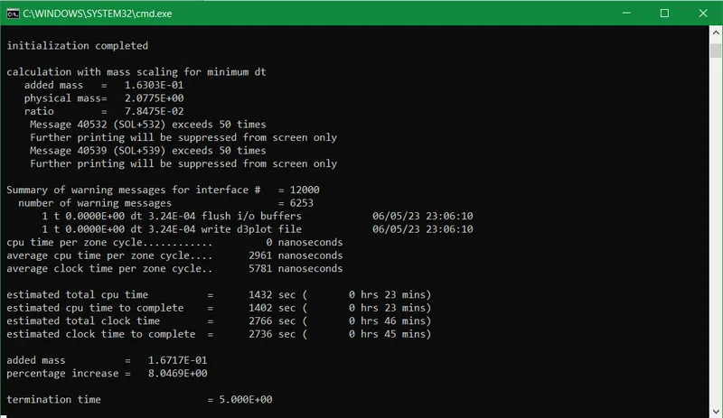
- DT2MS indicates the time step size for mass-scaled solutions. By introducing a mass scaling factor we can reduce the total clock time of the final simulation. It is introduced by adding mass to elements between 0-8% only. Henceforth by doing a trial and error method, we attained the exact value of 8% as displayed below in a table.
|
Trials |
Physical mass |
TSSFAC(Scale Factor) |
DT2MS |
Mass Percentage(%) increase |
Total clock time to complete(minutes) |
|
1 |
2.0775 |
0.9 |
-0.950e-04 |
0.00 |
155 |
|
2 |
2.0775 |
0.9 |
-1.000e-04 |
1.4e-06 |
152 |
|
3 |
2.0775 |
0.9 |
-2.000e-04 |
1.8e-1 |
82 |
|
4 |
2.0775 |
0.9 |
-3.000e-04 |
2.9 |
54 |
|
5 |
2.0775 |
0.9 |
-3.400e-04 |
6.2 |
52 |
|
6 |
2.0775 |
0.9 |
-3.550e-04 |
7.5 |
47 |
|
7 |
2.0775 |
0.9 |
-3.590e-04 |
7.9 |
45 |
|
8 |
2.0775 |
0.9 |
-3.600e-04 |
8.04 |
45 |
|
9 |
2.0775 |
0.9 |
-3.700e-04 |
9.1 |
43 |
- In the above table, the DT2MS value less than -0.950e-04 renders 0 mass percentage. The values of TSSFAC as 0.7,0.8 and 0.9 doesn't present much difference. So we take TSSFAC as a 0.9 value for all trials.
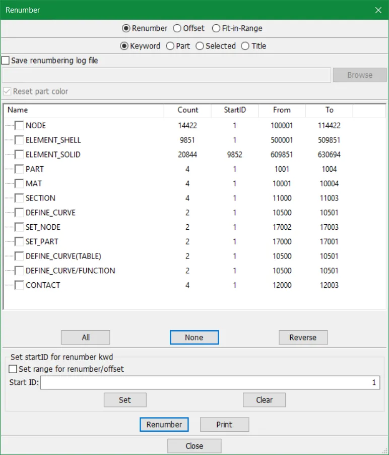
- After finalizing all cards in the Model>keyword tool we do the renumbering of all keywords as prescribed in the assignment. However for most of the keywords we manually regulated the numbers at the beginning of solving this model. This renumbering is done automatically by submitting a proper order as shown below. The tool used is in the sidebar menu as Model>Renumber
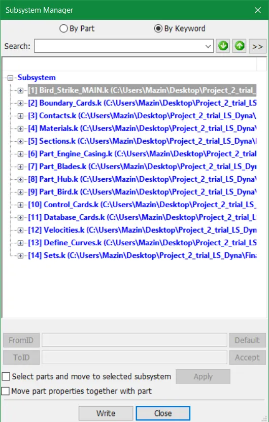
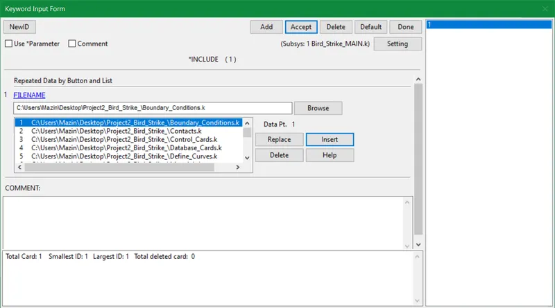
- Nevertheless, lastly, sub-systems of all keywords are created in the form of input .k files. These all subsystems are included in the include keyword of the main file. This step can be done in the beginning as it is useful for working with bigger projects.
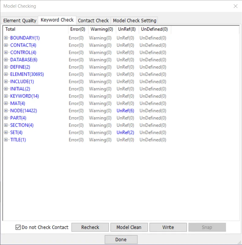
- Eventually after doing model checking no errors are found so without further ado simulation is initiated.
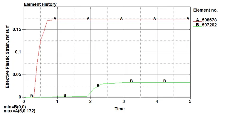
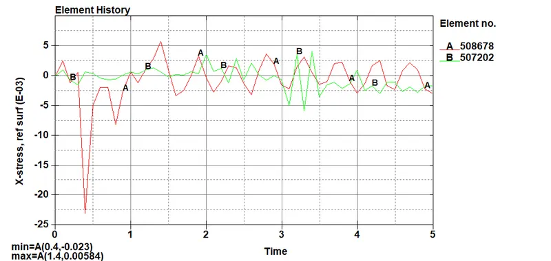
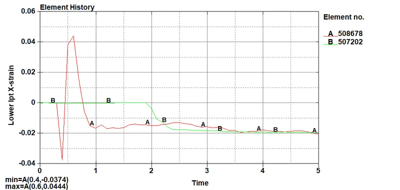
- The final simulation shows that in this case bird sand blades are plastically deformed. The 5 blades are affected by the bird component post-impact.
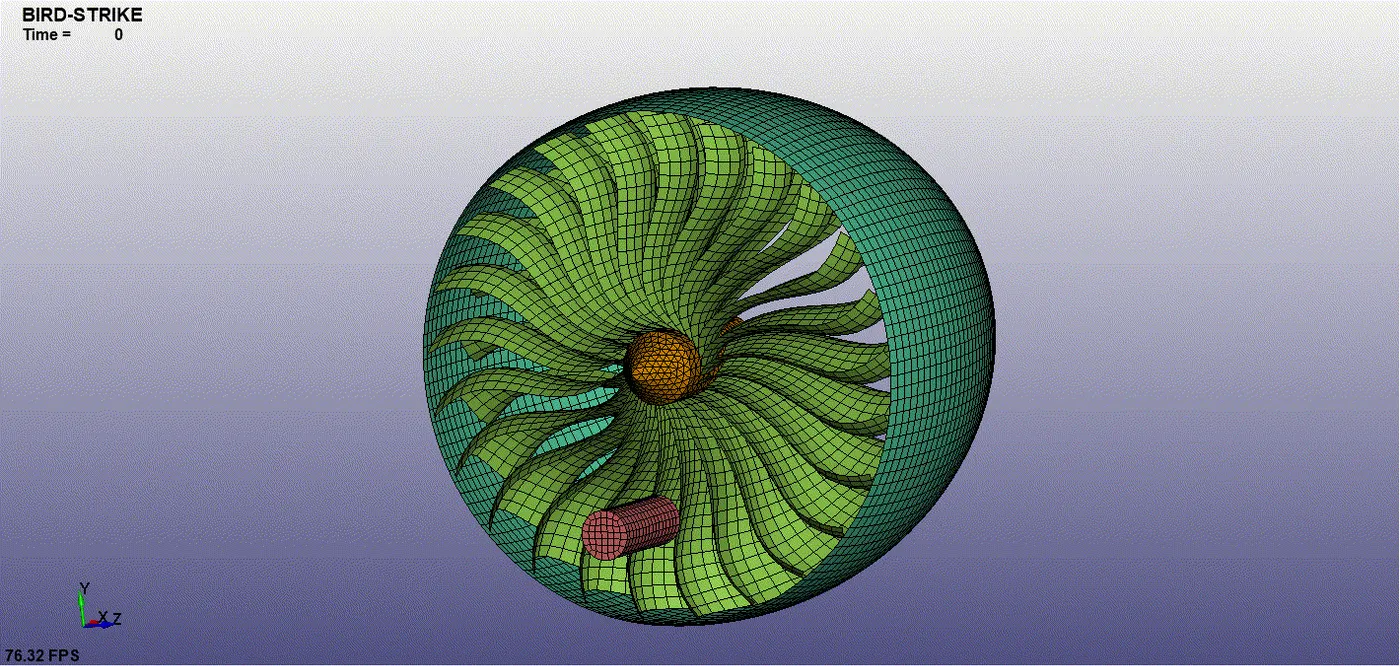
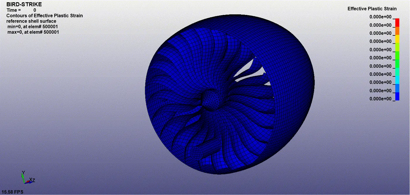
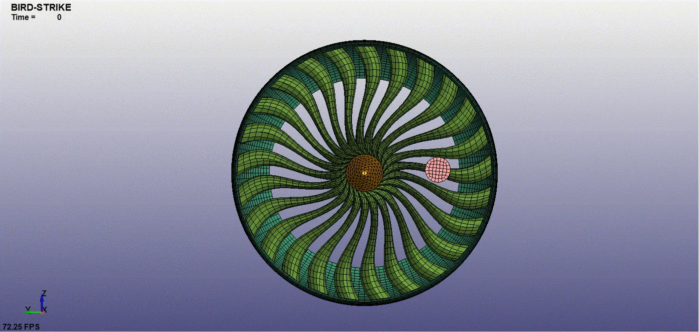
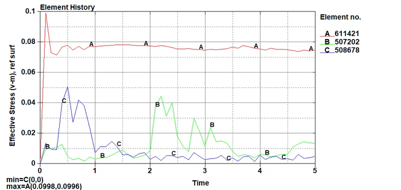
Effective stresses (v-m)
- 611421 = Hub 3D element shows maximum stress = 0.0996 Kg mm/ms^2
- 508678 = Blade element of first contact with bird = 0.05 Kg mm/ms^2
- 507202 = Blade element of the last contact with bird = 0.04 Kg mm/ms^2
Effective Plastic Strain
- 508678 = Blade element of first contact with bird(Maximum plastic strain) = 0.17
- 507202 = Blade element of the last contact with bird = 0.03
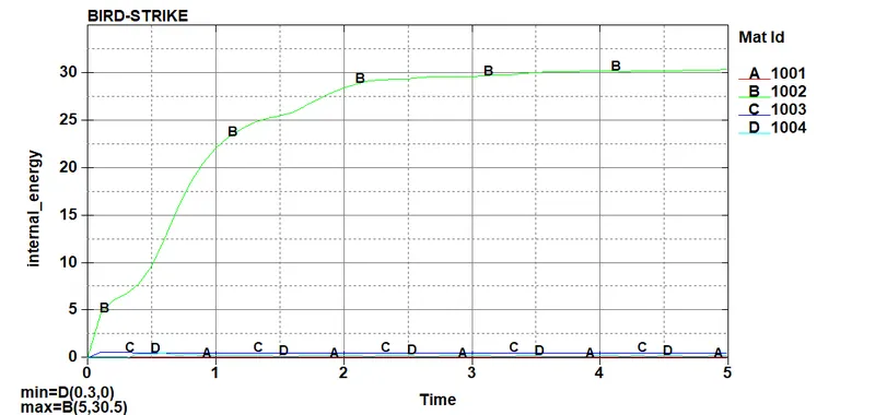
- Total Energy = 295 Joules = 295 Kg mm^2/ms^2

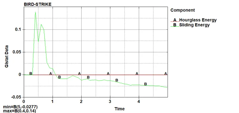
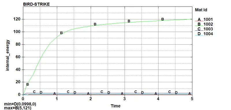
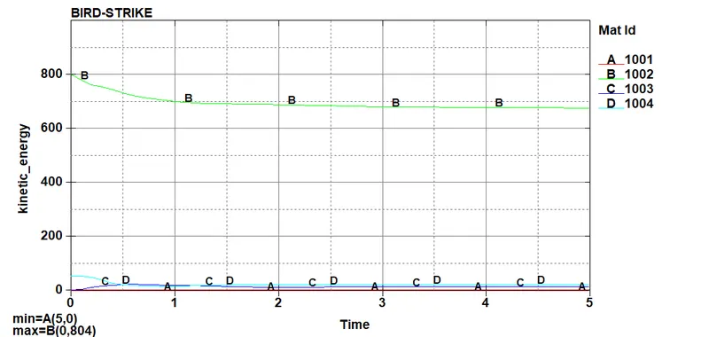
- A, B, C and D determine the part ID's in the plots below for several types of energies.
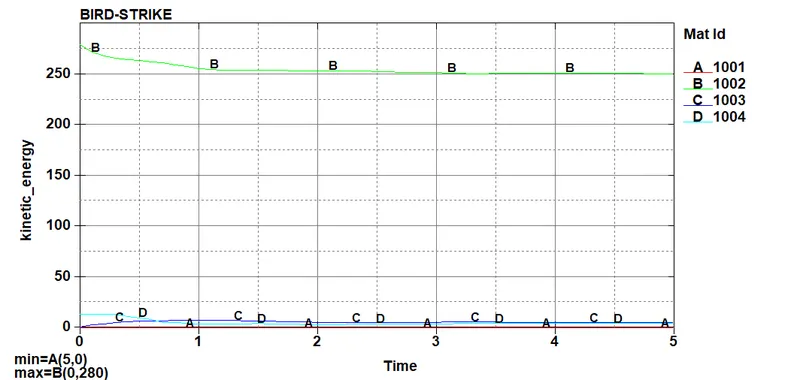
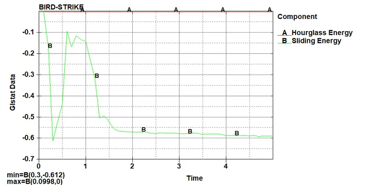
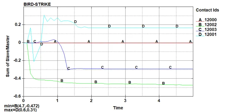
- The 'Sliding Energy' in GLSTAT is equivalent to the SLEOUT value for the "sum of slave/master.
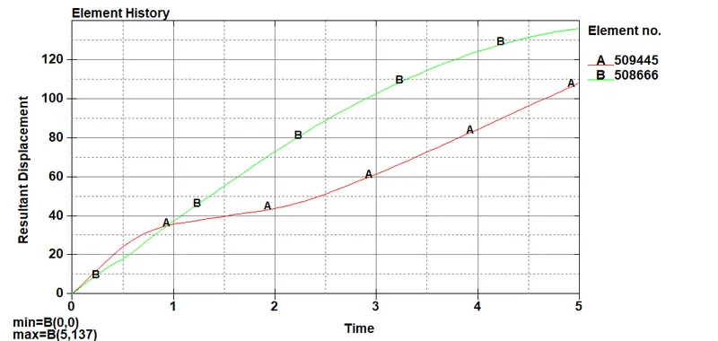
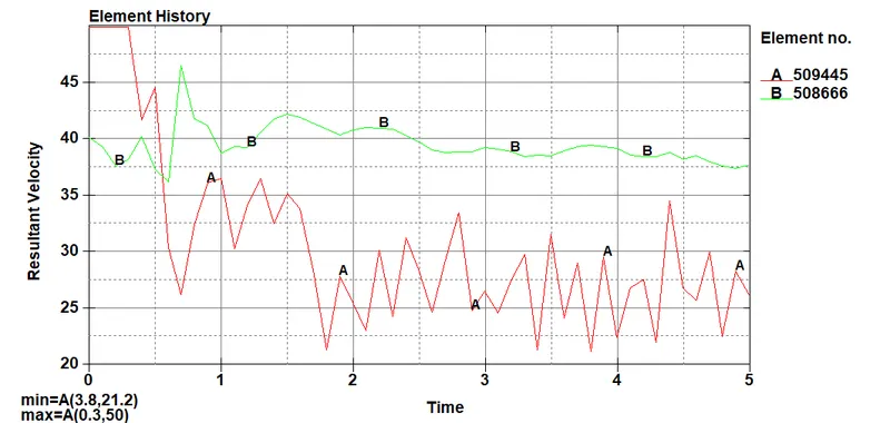
- In the resultant displacement and velocity plots, 509445 is one of the elements of the bird part that comes in contact with blades during simulation. Also, 508666 is one of the blade elements that gets deformed by the impact of the bird part.
Resultant Displacement:
509445 = Bird element = 137 mm
508666 = Blade element = 108 mm
Resultant Velocity:
509445 = Bird element = 50mm/ms
DEBUGGING AND ADDITIONAL CASES:
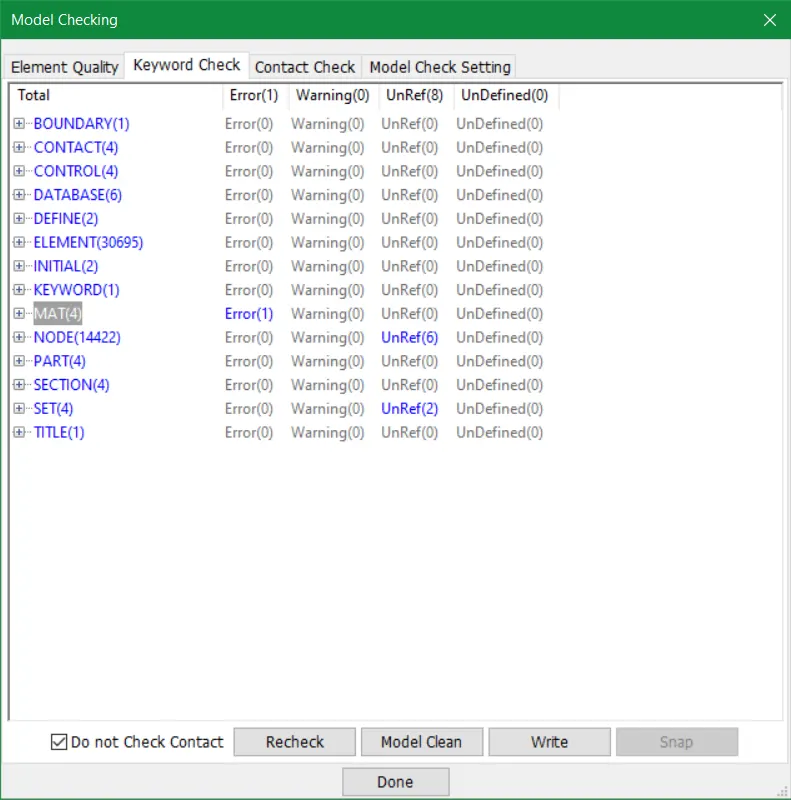
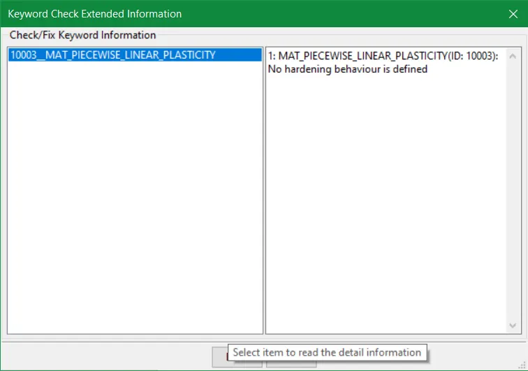
- The model provided above gave precise results but we faced some difficulties while performing this analysis. The errors were numerous but some prominent errors are displayed below. The 0 value of the tangent modulus affects the strain-hardening behaviour of the hub material. So after certain calculations, the error was rectified by providing a certain value.
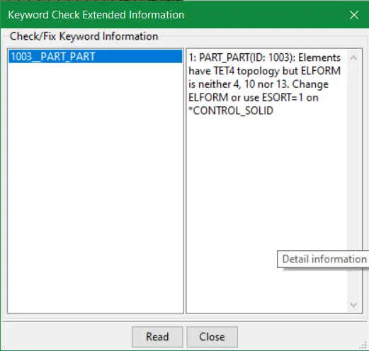
- The Element formulation as 1 by default didn't work for the solid hub component even after trying other formulations. So to discard an extra control_solid card a value of 10 was given which is a one-point tetrahedron.
- Another case was tested by only regulating the initial_velocity_generation card only with the following parameters:
Bird translational velocity (v) = 100 mm/ms
Blades Rotational velocity (omega) = 1 rad/ms
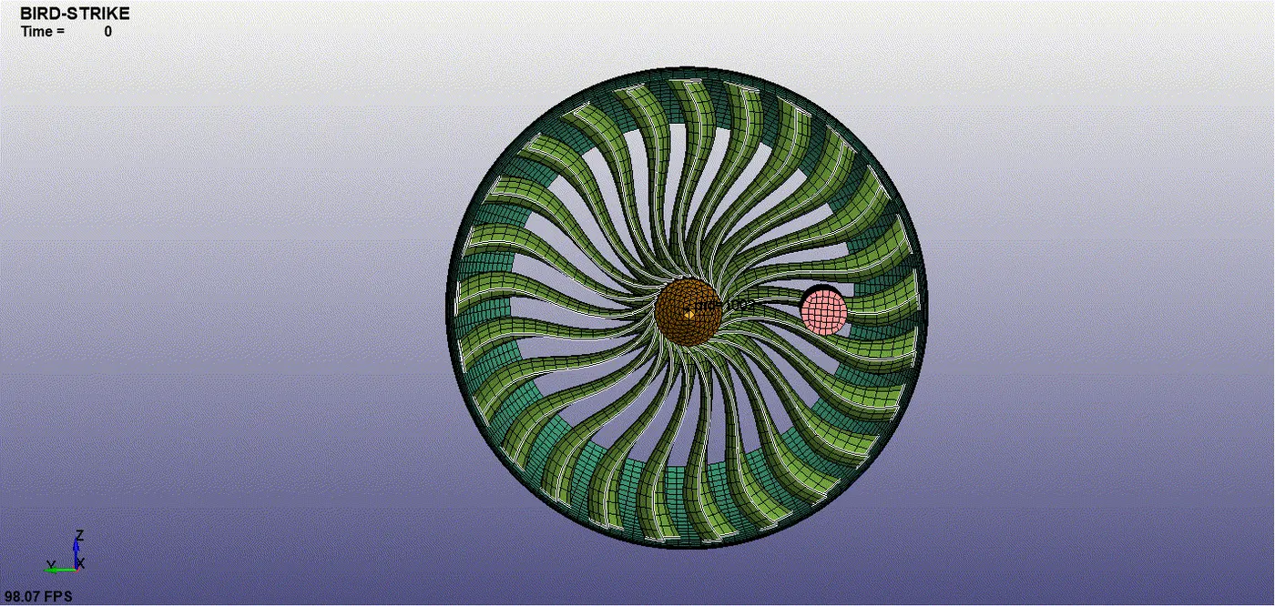
- This influence was huge as the velocity for both blades and bird parts was high. Some elements of the blades were deleted by the bird due to high velocity and seven blades were impacted in this case.
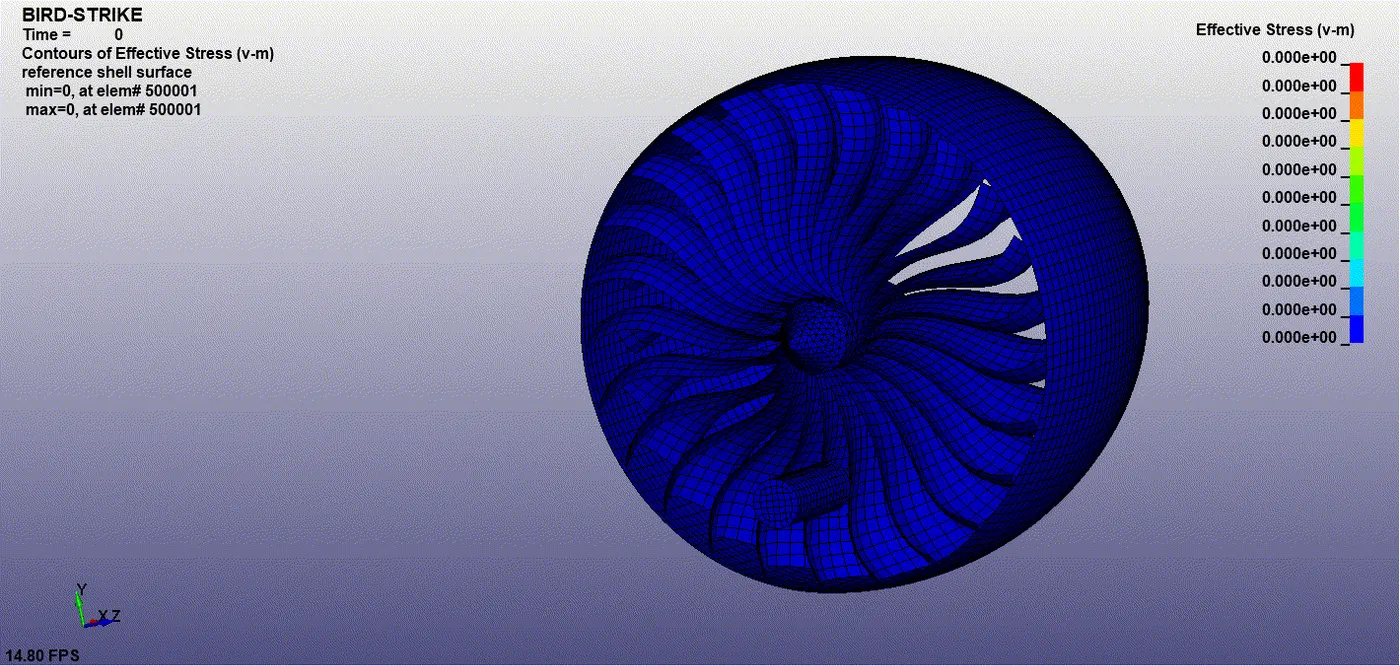
- Another thing was examined and observed due to 1 rad/ms, the clearance between blades was shortened. There was a distortion in the shape of each blade with or without the impact of the bird. This shows a kind of instability in turbofan components in relation to design.
- The relevant data of all quantities as aforementioned earlier is shown here also in the form of plots.
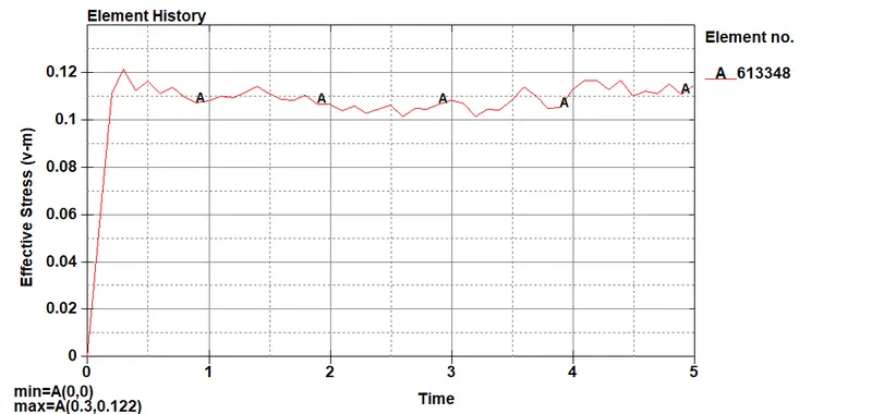
Effective stresses (v-m)
- 613348 = Hub 3D element shows maximum stress = 0.0996 Kg mm/ms^2
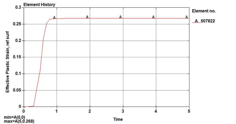
Effective Plastic Strain
- 507822 = Blade element of first contact with bird(Maximum plastic strain) = 0.268
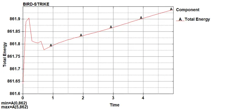
- Total Energy = 862 Joules = 862 Kg mm^2/ms^2
- The sliding energy is too much negative in this case and abrupt increases in negative contact energy may be caused by undetected initial penetrations.
Resultant Displacement:
509445 = Bird element = 270 mm
508666 = Blade element = 112 mm
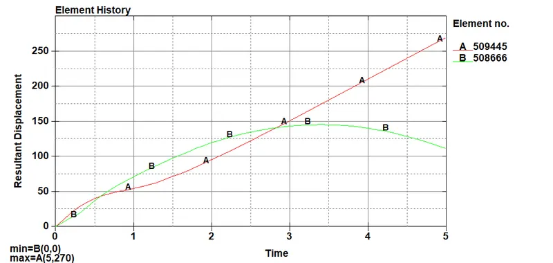
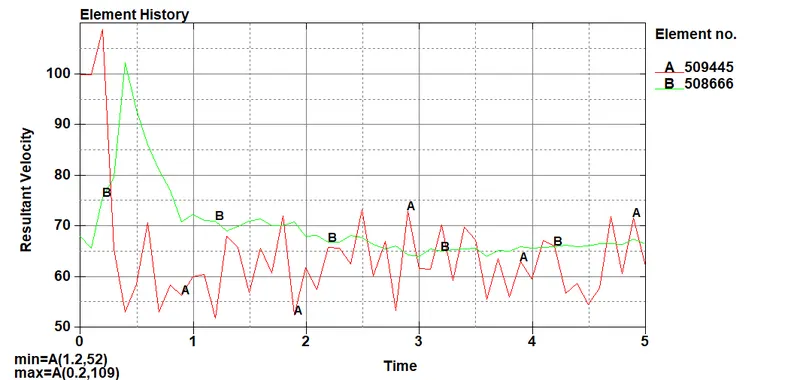
- This additional case gave us unstable and huge results in the context of stress, strain, resultant displacement and other parameters. Although the case we finalized at the start with 0.59 rad/ms rotational speed of blades gave pretty decent output.
- Nevertheless, after certain formulations and tests, we hypothesized and identified a specific assessment for this project. The observations below will provide a non-failure of analysis for this model.
Hence Rotational/Angular velocity of the blades and hub (omega) should be < 1.5 rad/ms
The translational velocity of the bird (v) should be < 150 mm/ms
CONCLUSION:
- This project clears all the fundamentals by using a generic explicit solver with industry-oriented experience.
- The trials and tests did provide a better insight into research and analysis while pursuing CAE models.
- The analysis portrayed various behaviours of all the essential materials designated to each part of the turbofan model under variable conditions and parameters.
- The failures while doing the analysis in this project outlines a pavement for innovating design changes of the model.
- The collaboration of all tools and manuals of LS-dyna for this project provides an advancement in pursuing the post-processing and solving extensively.
https://drive.google.com/drive/folders/131i-7V0YhH64upAY0K9gMQXGvEF7EMU5?usp=sharing