Week 2 Bevel Gear Challenge
STATIC STRUCTURAL ANALYSIS ON BEVEL GEARS
INTRODUCTION
Grid Dependency Test
An examination of how the output of a finite element simulation varies when several meshes, or grids, are applied to represent the geometry under consideration is known as a grid dependence study in FEA. Ensuring that the numerical solution achieved with a certain grid size or configuration does not significantly differ from another is the aim of this kind of study.
Engineers can determine which mesh configurations yield more accurate solutions and utilize that information to inform their design decisions by knowing how various mesh configurations affect the results. Because erroneous simulations prevent needless design iterations or tests, this lowers computational costs while also improving the quality of the study.
It is possible to conduct mesh dependency studies by executing several simulations with various mesh layouts and sizes. After each simulation's findings are acquired, they have to be compared to spot any notable variations in the correctness or dependability of the solutions. If disparities arise throughout the several simulations, engineers might have to modify their mesh arrangement to attain a uniform outcome throughout all testing.
The moment at which the numerical solution found with one grid size or configuration does not materially differ from another is referred to as convergence in grid dependence research. This suggests that additional tweaking is not required because an acceptable degree of accuracy has been reached. Engineers should examine results from several simulations using various meshes until they obtain a consistent result across all tests to ensure convergence.
Boundary conditions can significantly affect a mesh dependence study's findings. Discrepancies between the two answers may arise, for instance, if boundary conditions are considered in one simulation but improperly taken into consideration in another. In a similar vein, variations in the kinds or strengths of boundary conditions (such as displacement versus force) may also be noticed in different simulations. These variations must be taken into consideration before any trustworthy inferences can be made from the analysis.
Longer runtimes are a result of larger simulations that require more data to handle and store as accuracy increases. Mesh convergence studies are a common tool used by engineers to find the best possible trade-off between accuracy and runtime.
Bevel Gears
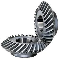
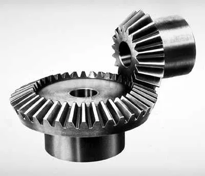
Bevel gears have conically formed tooth-bearing faces and are gears where the axes of the two shafts cross. Bevel gears can be made to operate at different angles, but they are typically installed on shafts that are 90 degrees apart. A pitch cone, as the name implies, is the pitch surface of a bevel gear. Bevel gears are highly helpful in machines that are frequently utilized in mechanical settings because they convert linear energy into vertical power. Bevel gears can have straight, spiral, or "zerol" teeth.
Locomotives, maritime applications, cars, printing presses, cooling towers, power plants, steel mills, railway track inspection equipment, etc. are just a few of the many varied applications for the bevel gear.
Differential drives, like those on a cornering car, employ bevel gears to provide power to two axles rotating at different speeds.
Bevel gears can have straight, spiral, or "zerol" teeth.
A hand drill's primary mechanism is made of bevel gears. The bevel gears shift the chuck's rotation to a horizontal one when the drill handle is rotated in a vertical direction. An additional benefit of bevel gears in a hand drill is that they increase the chuck's rotational speed, enabling the drilling of a variety of materials.
A crucial part of rotorcraft driving systems are spiral bevel gears. These parts must function at high loads, high speeds, and for a significant number of load cycles. In this application, the shaft from the horizontal gas turbine engine is redirected to the vertical rotor using spiral bevel gears. Speed reducers can also be made with bevel gears.
OBJECTIVES
1)Write a few words on what a grid dependency test is and its use.
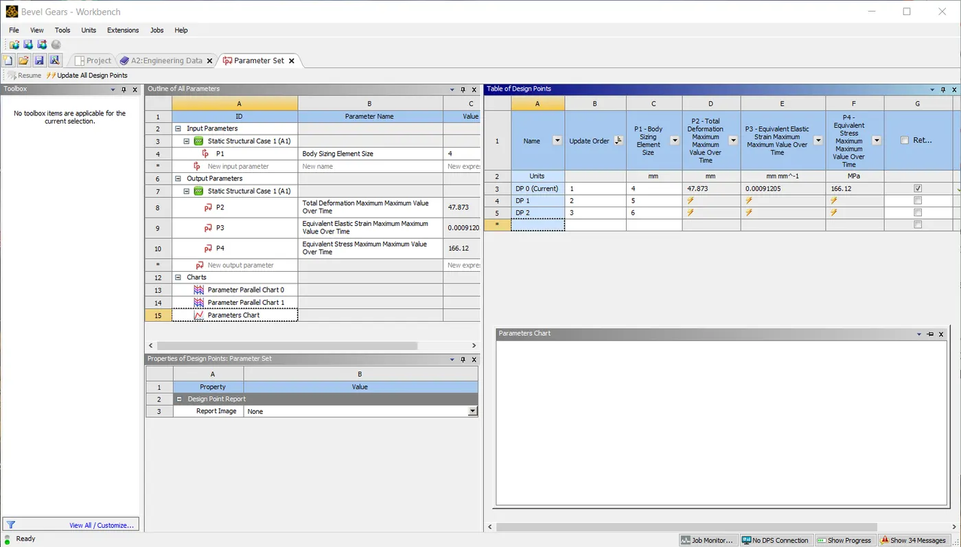
2)Perform a grid dependency test for the Bevel gear simulation for mesh sizes of 6,5 and 4 mm
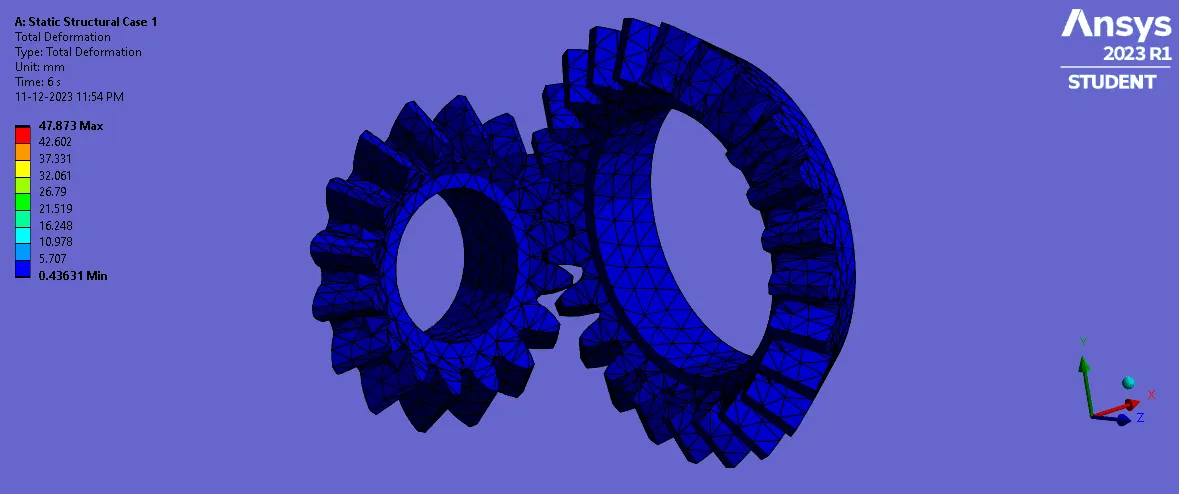
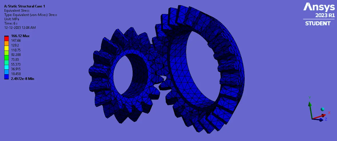
3) Solve for Von-Mises stress, Equivalent elastic strain, and Total Deformation using the previously mentioned mesh sizes.
4) Present your findings in an organized manner.
PROCEDURE
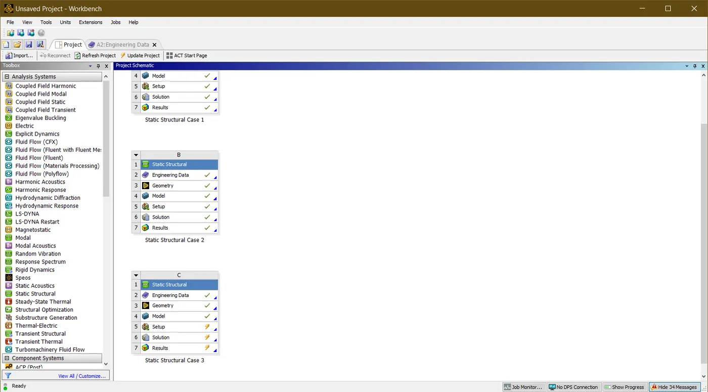
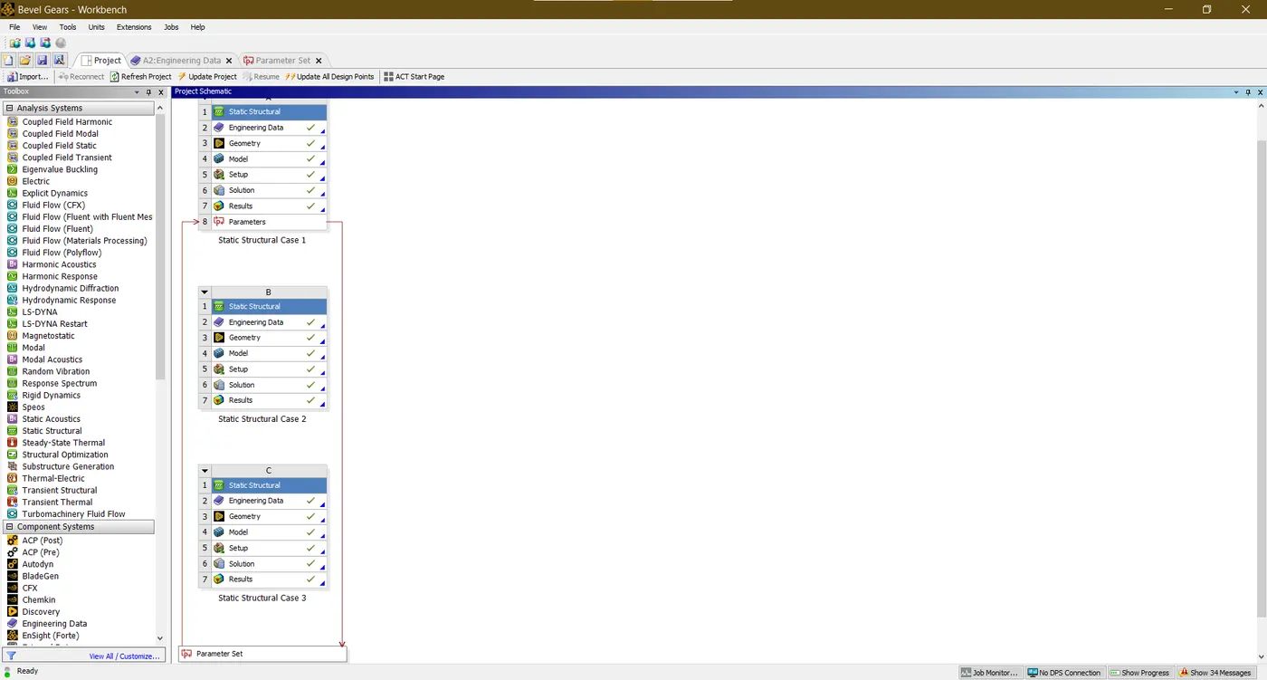
- The assignment is divided into three cases regarding the mesh sizes of the components.
CASE 1
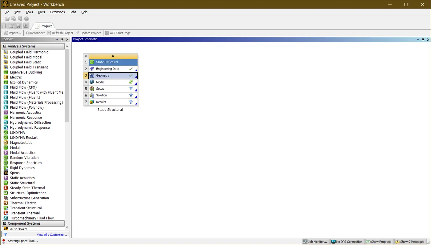
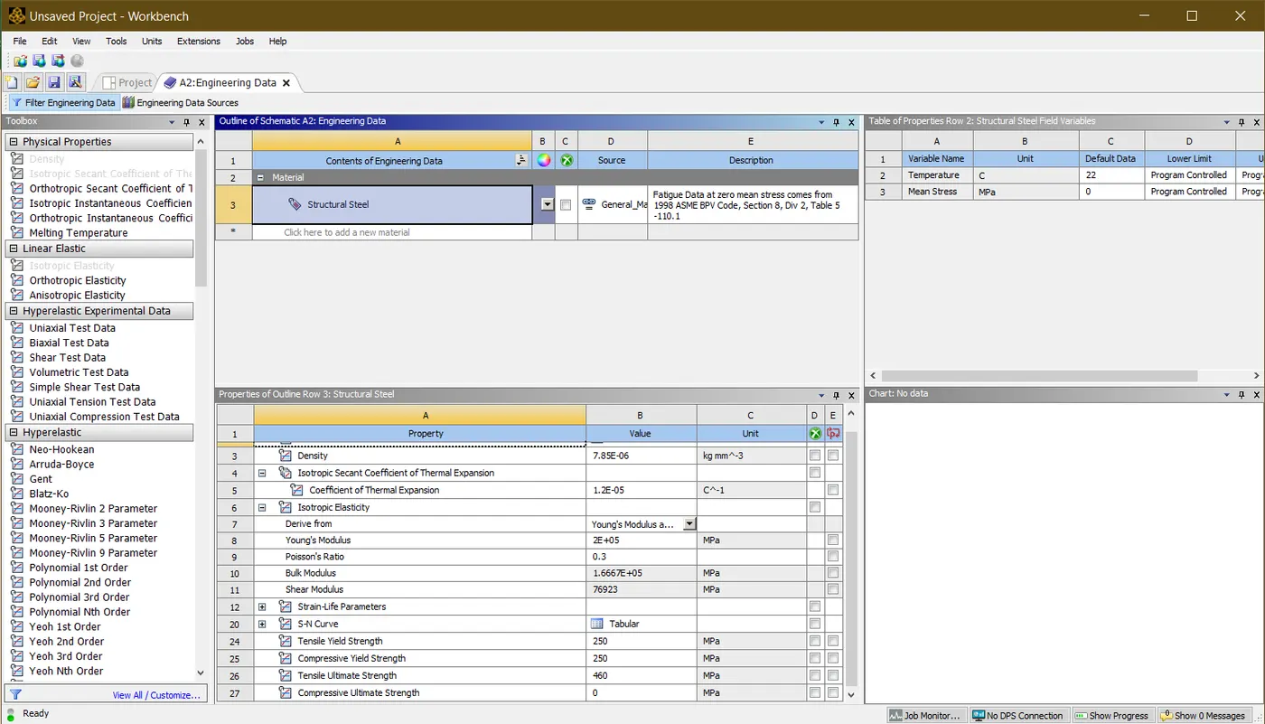
- The new Static structural system is developed in the Project schematic of ANSYS Workbench. In Engineering data, the structural steel is assigned as a default material for the model. The standard unit system used for this assignment is Kg,mm,N,s,Degrees.
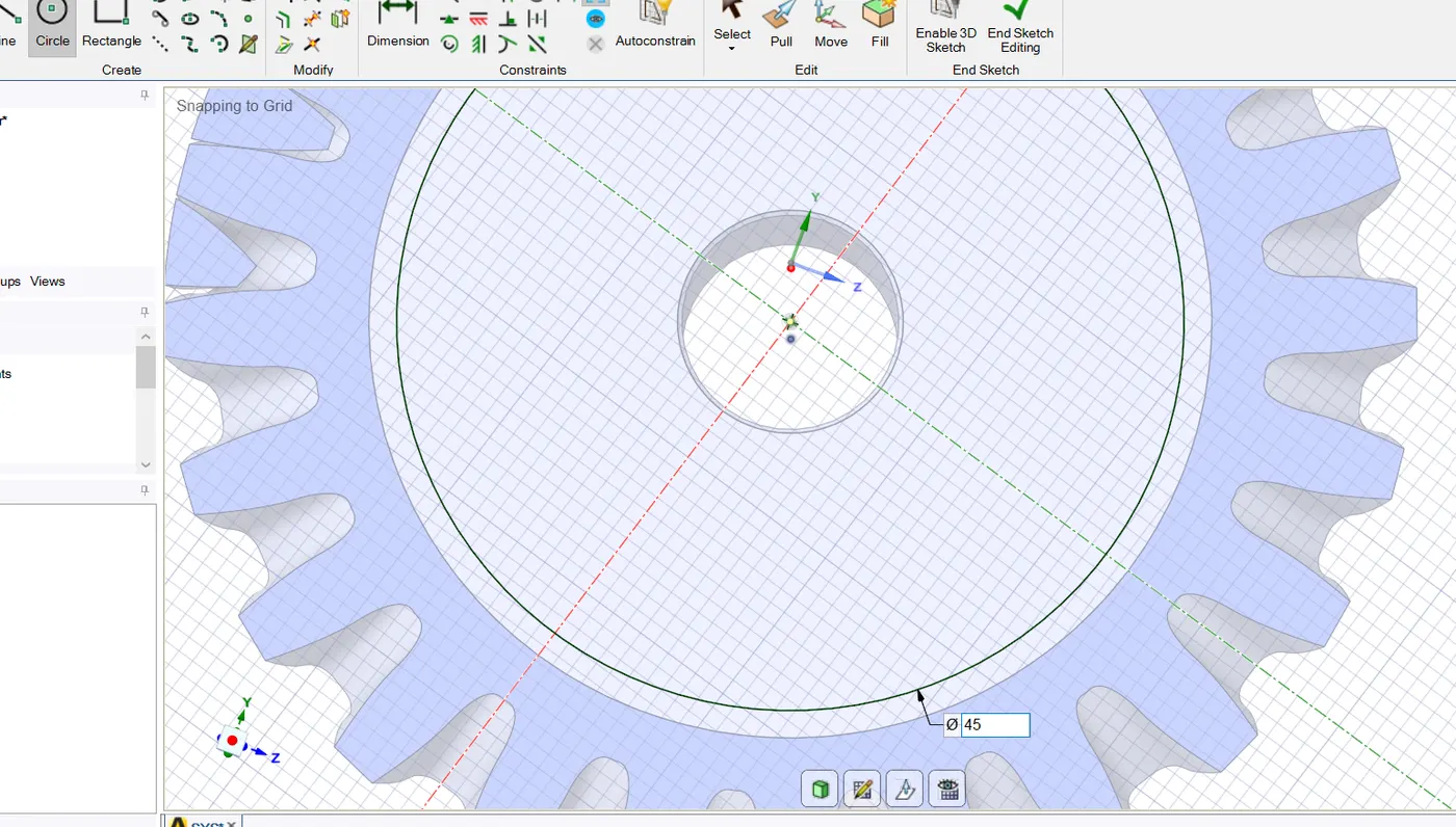
- The bevel gear is imported in the geometry item and edited in the Space claim. The middle portion of both gears is pulled out and removed.
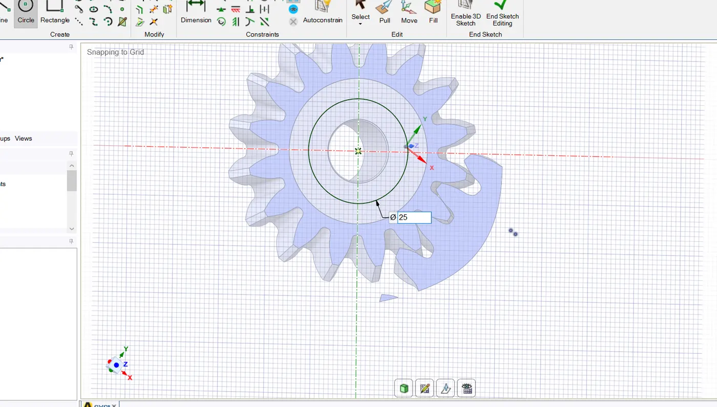
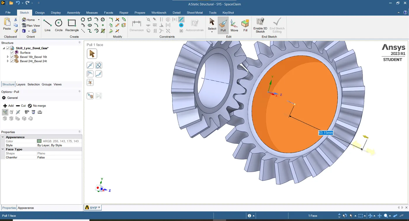
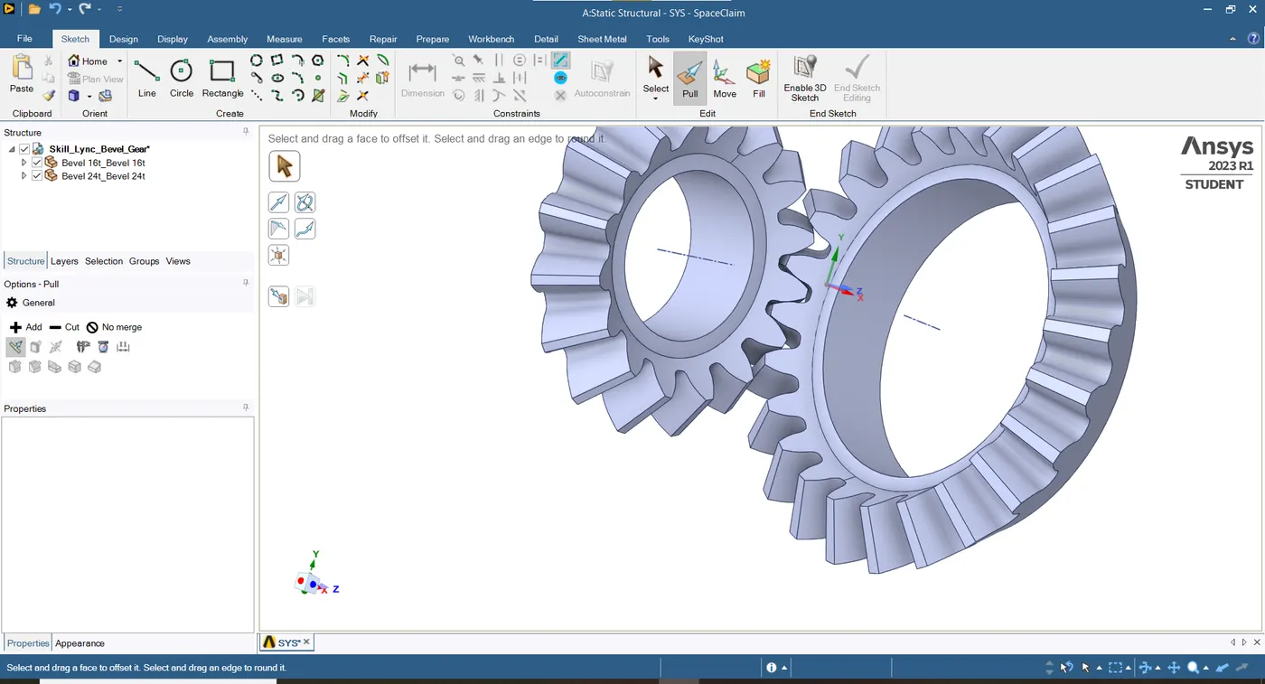
- The frictional contact is provided between both gears with adjust-to-touch interface treatment and zero frictional coefficients. The Augmented Lagrange is allocated as the contact formulation for this model.
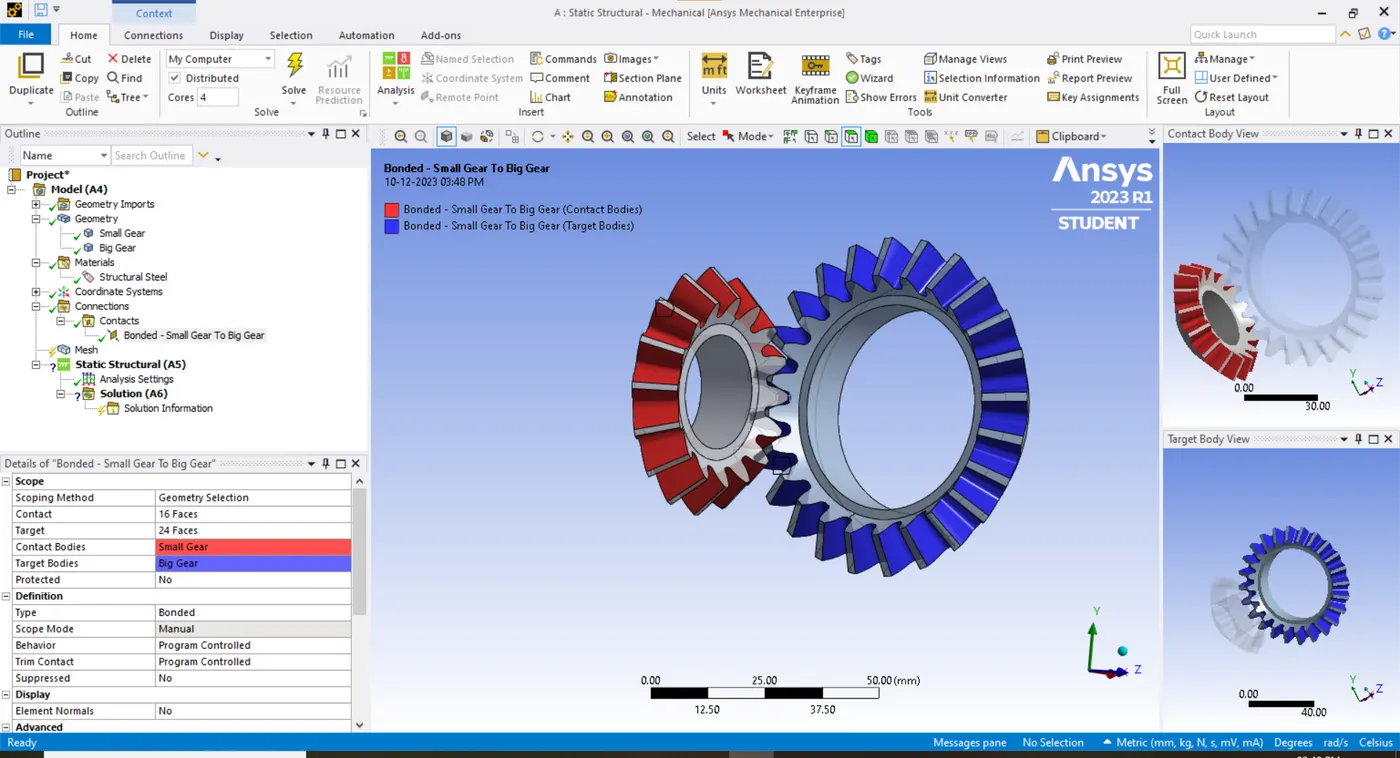
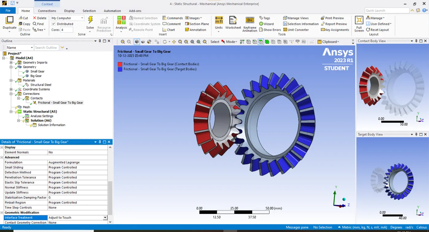
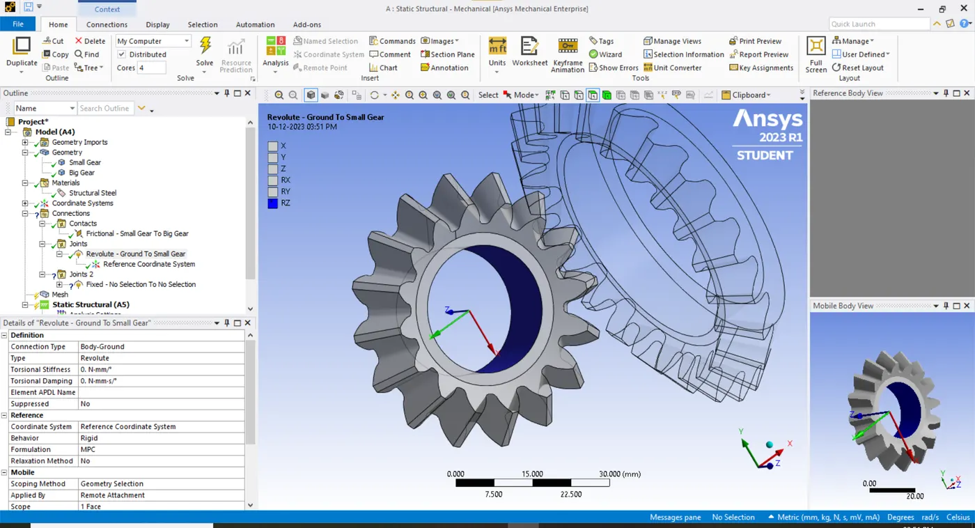
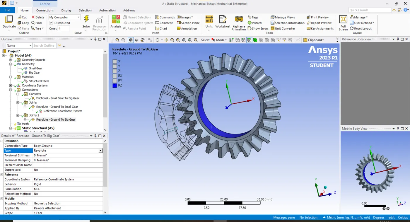
- The revolute joints for both bevel gears are registered to acquire rotational motion respective to a specific direction. The direction of Z-axis in reference coordinate system defines the clockwise and counter clockwise direction of each gear.
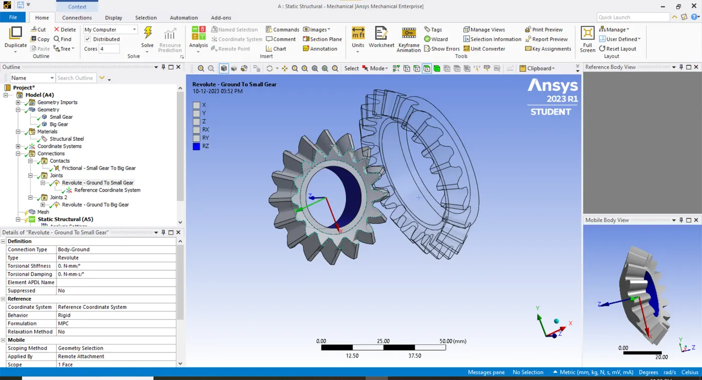
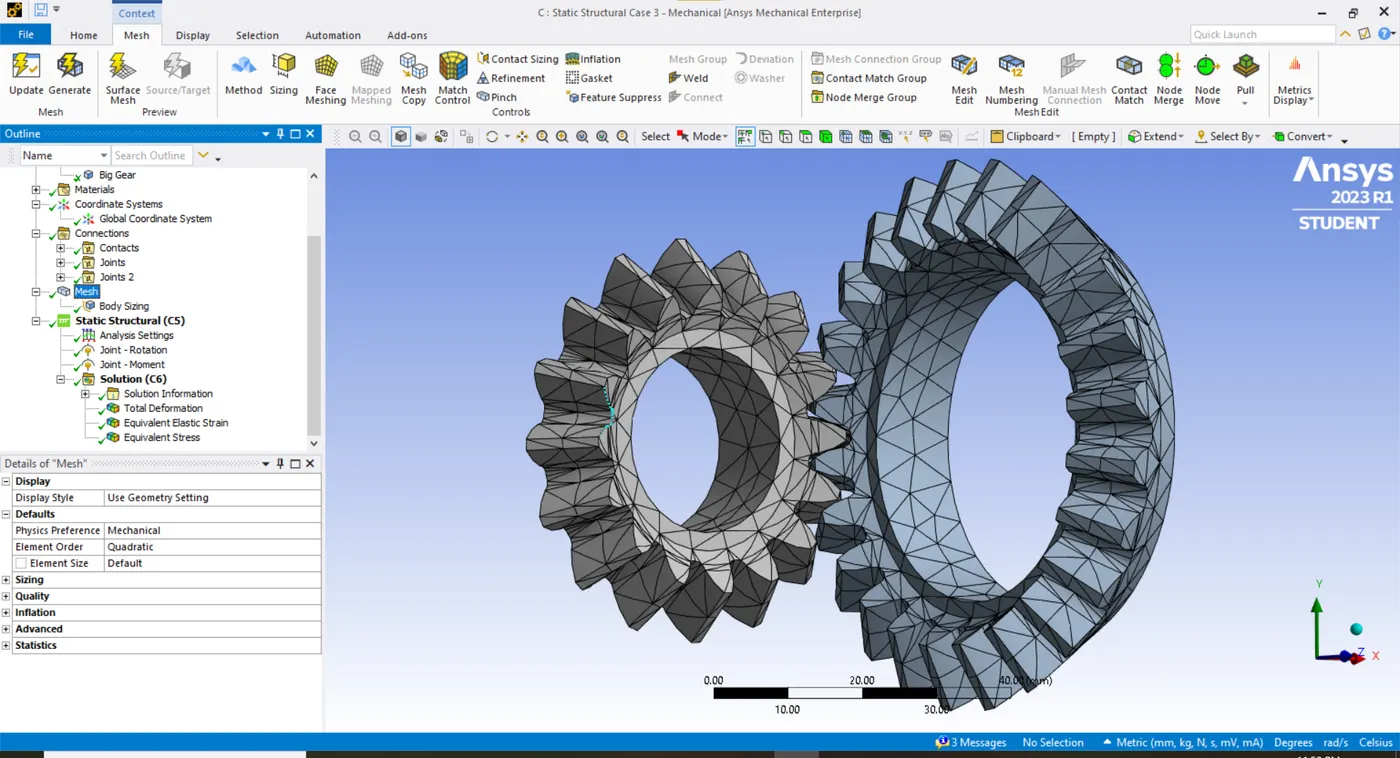
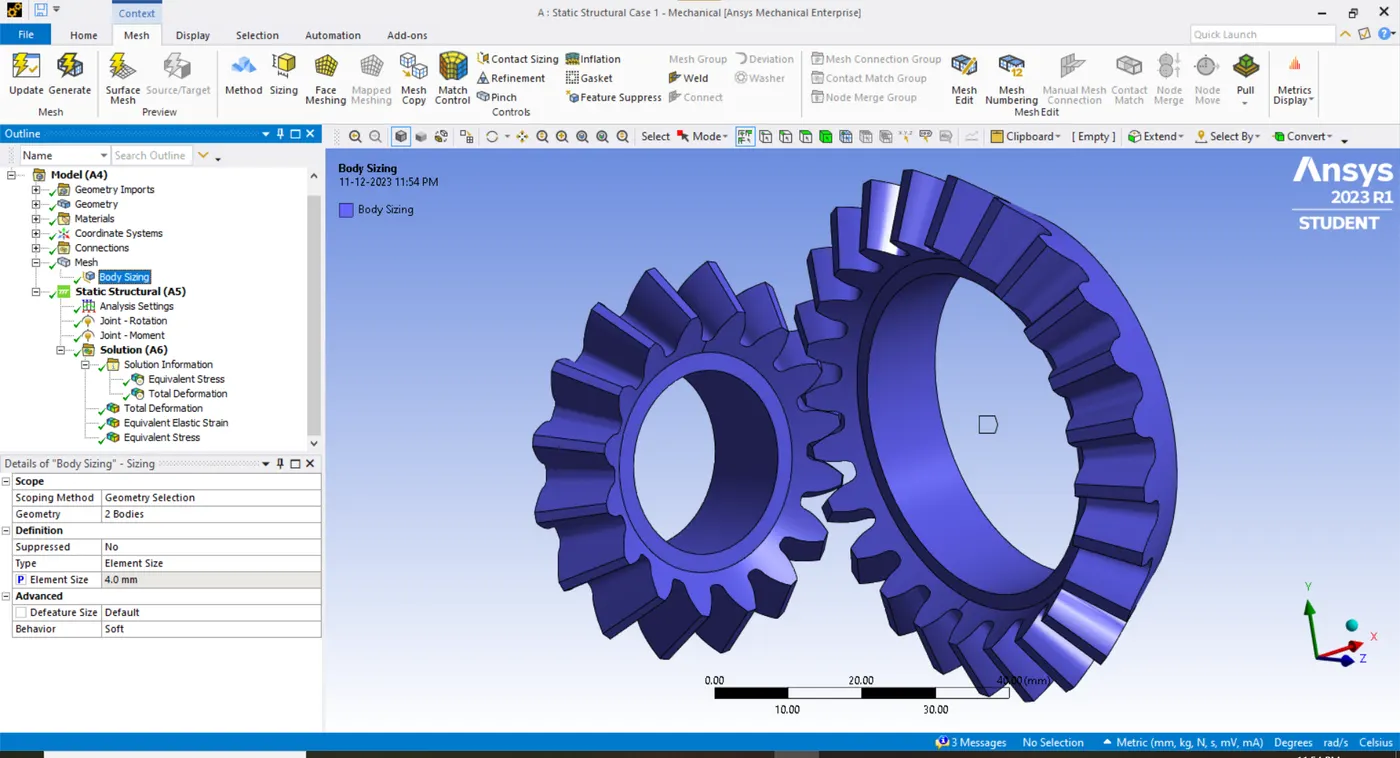
- The 4mm mesh size is attributed in this case to both gear bodies.
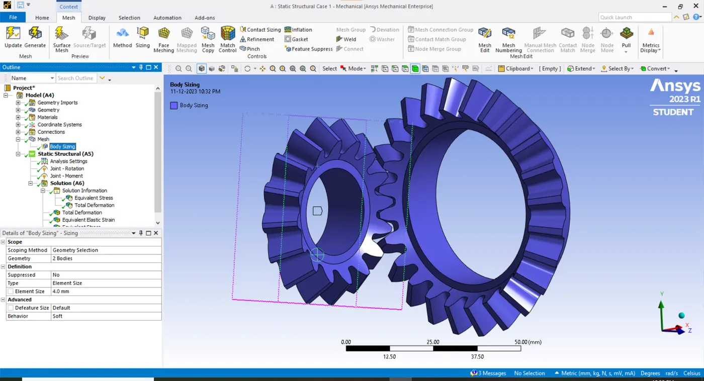
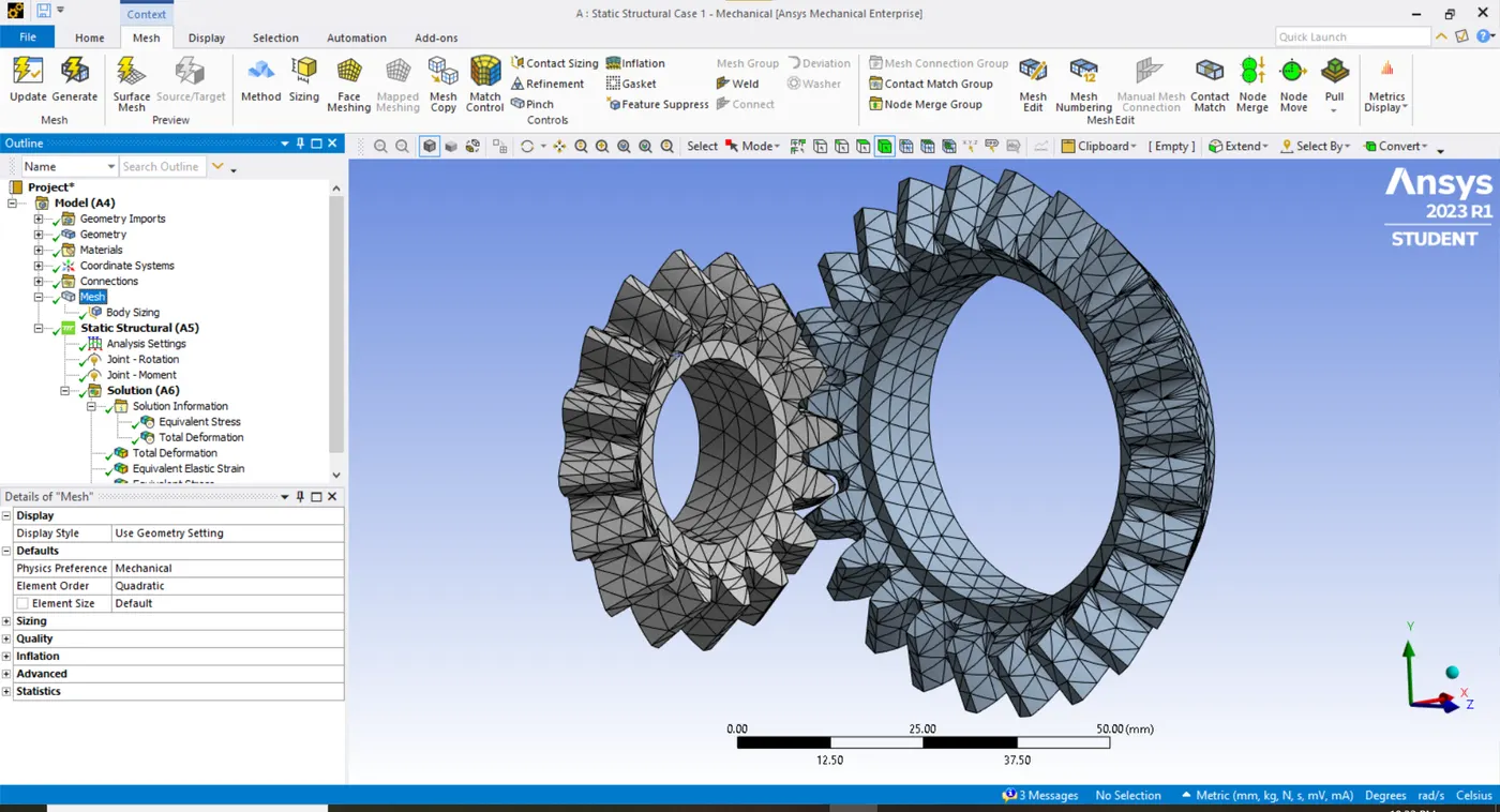
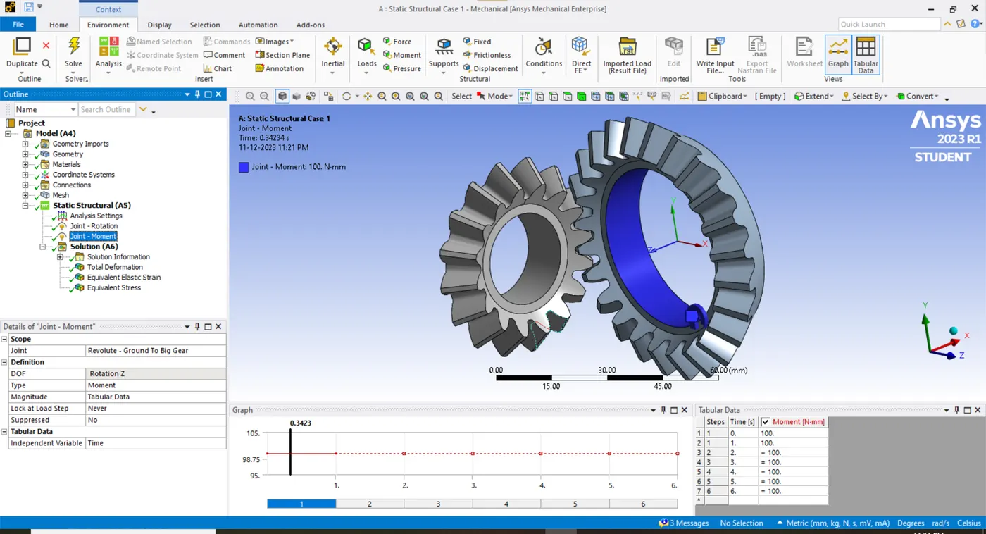
- In loading conditions, the smaller gear is provided with an incremental rotational displacement step-wise. The constant moment of 100 N-mm is provided for the large gear at every step.
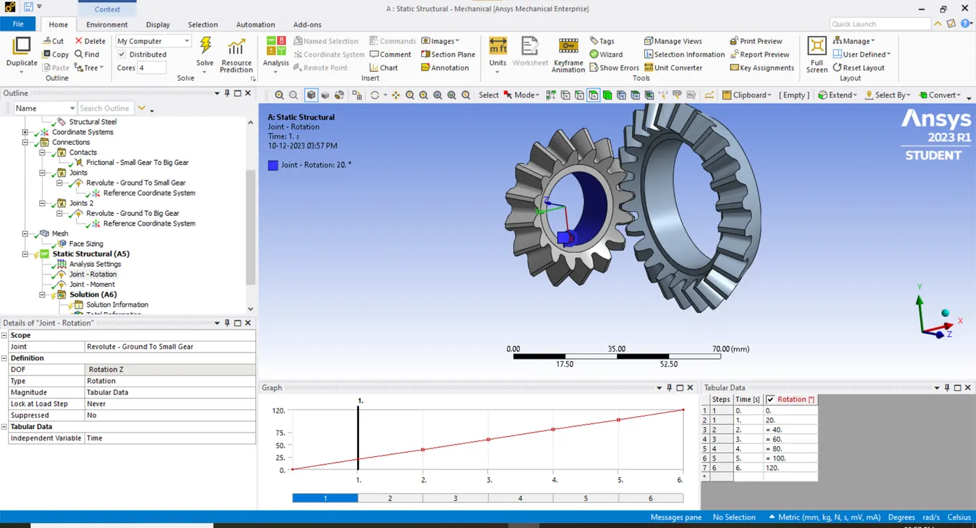
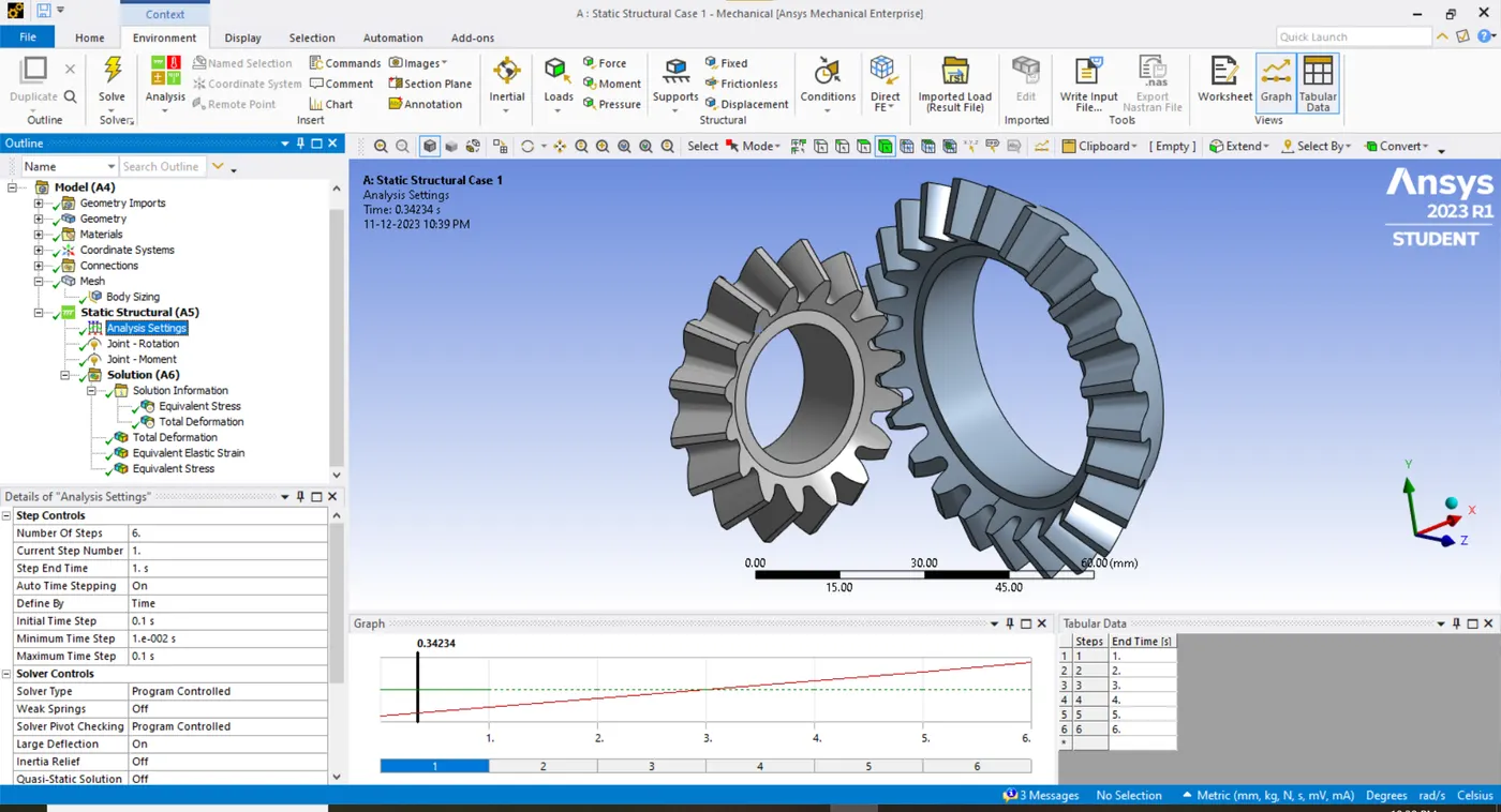
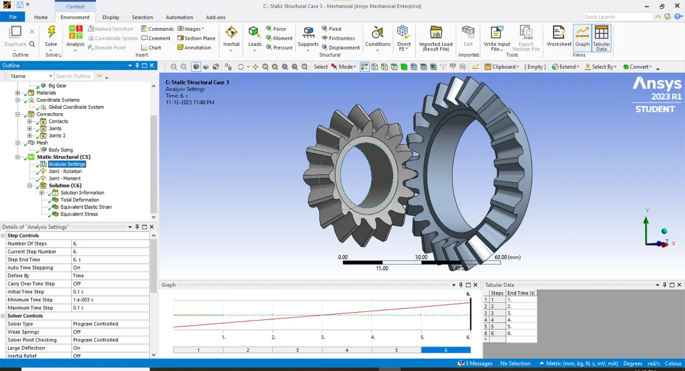
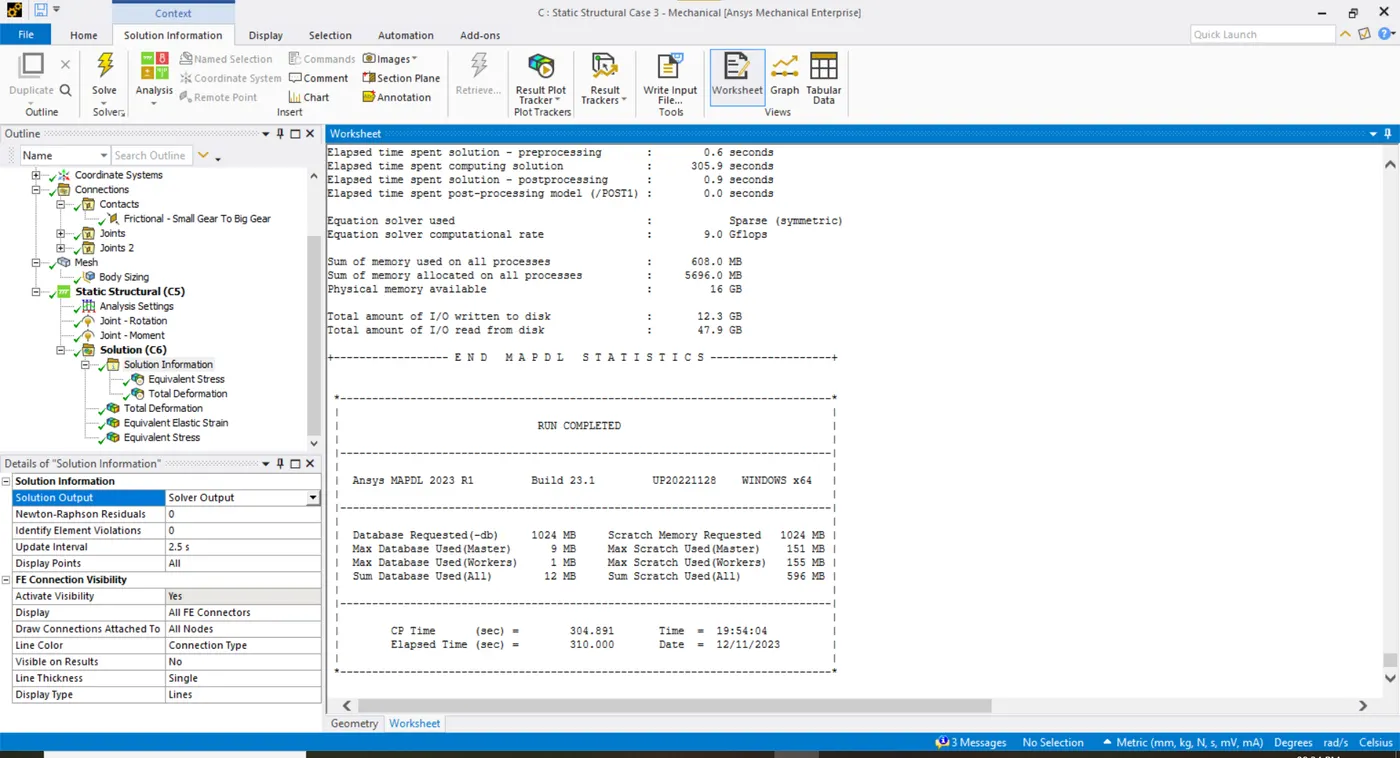
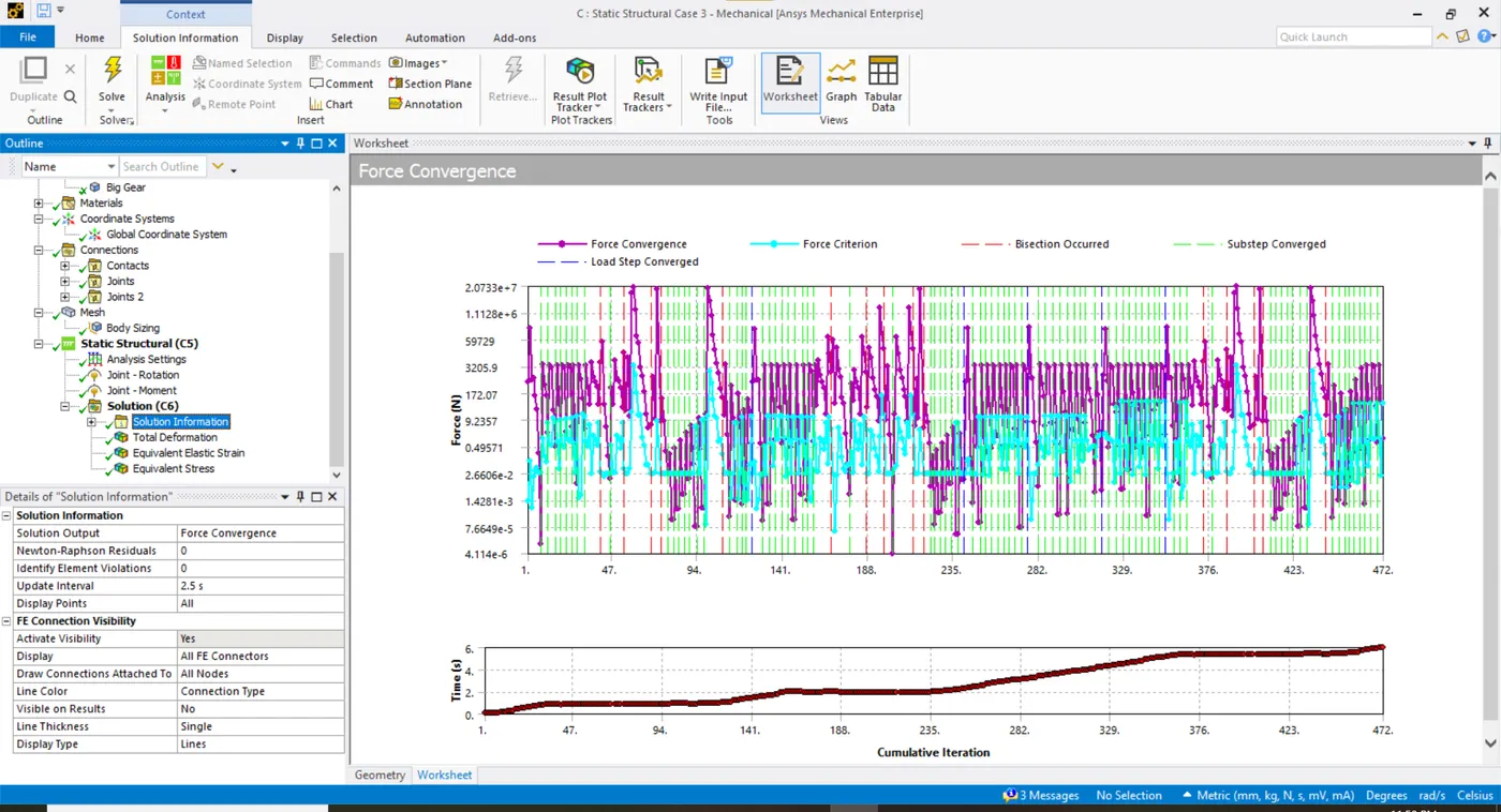
- In analysis settings, the solution is divided into 6 load steps and the large deformation is turned on. The time step size is altered w.r.t the model configuration.
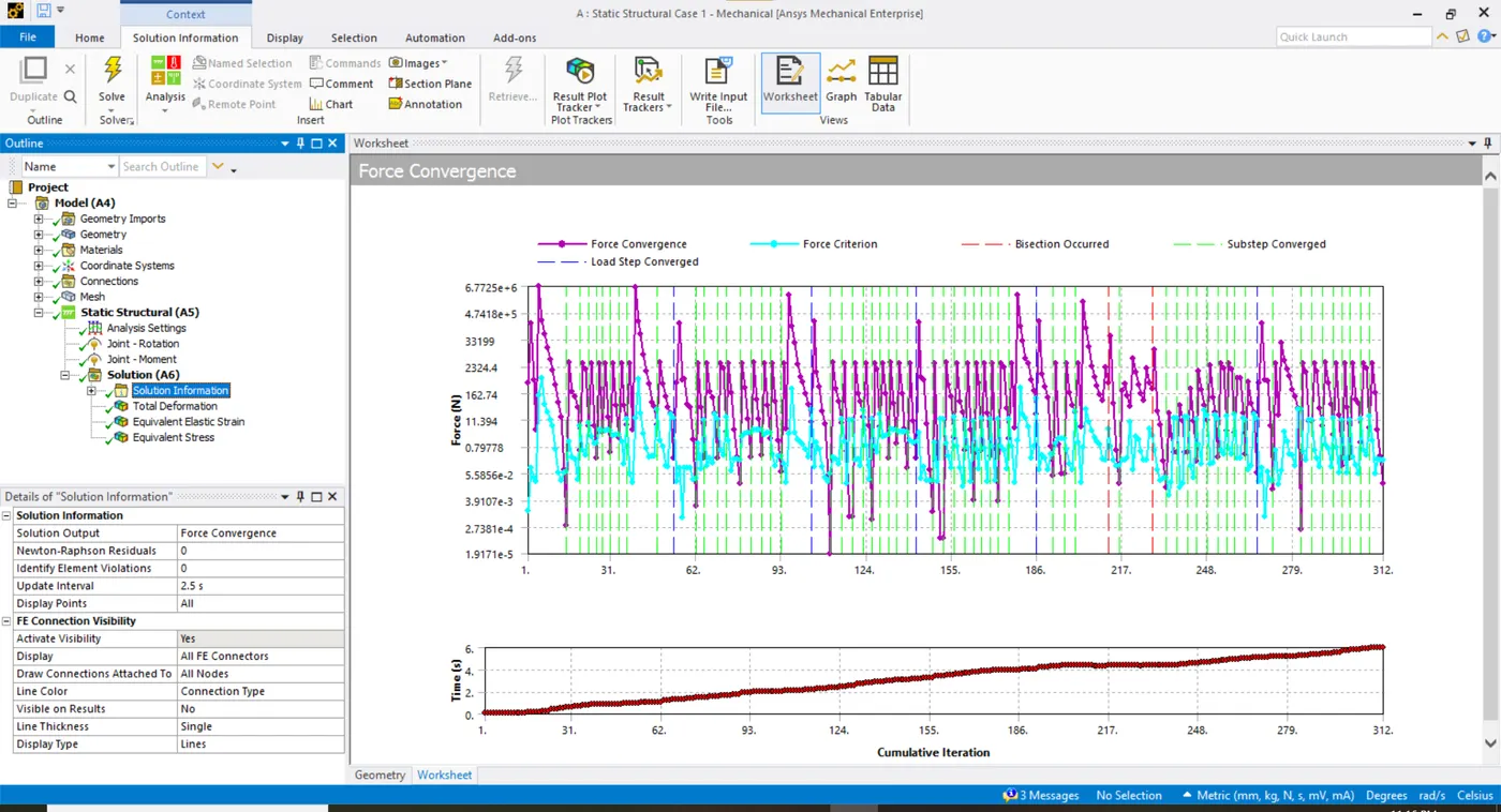
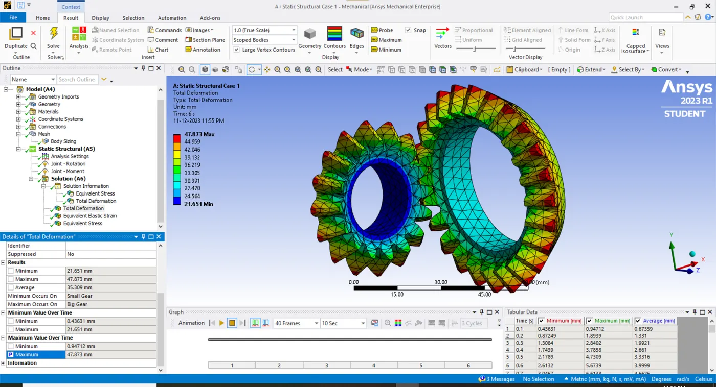
- The load steps are smoothly converged for the whole solution and the results are achieved correspondingly.

CASE 2
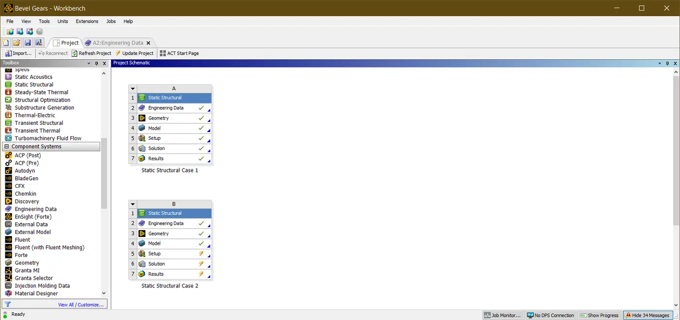
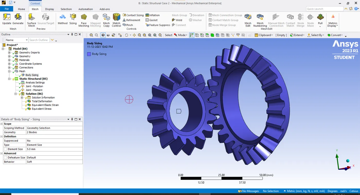
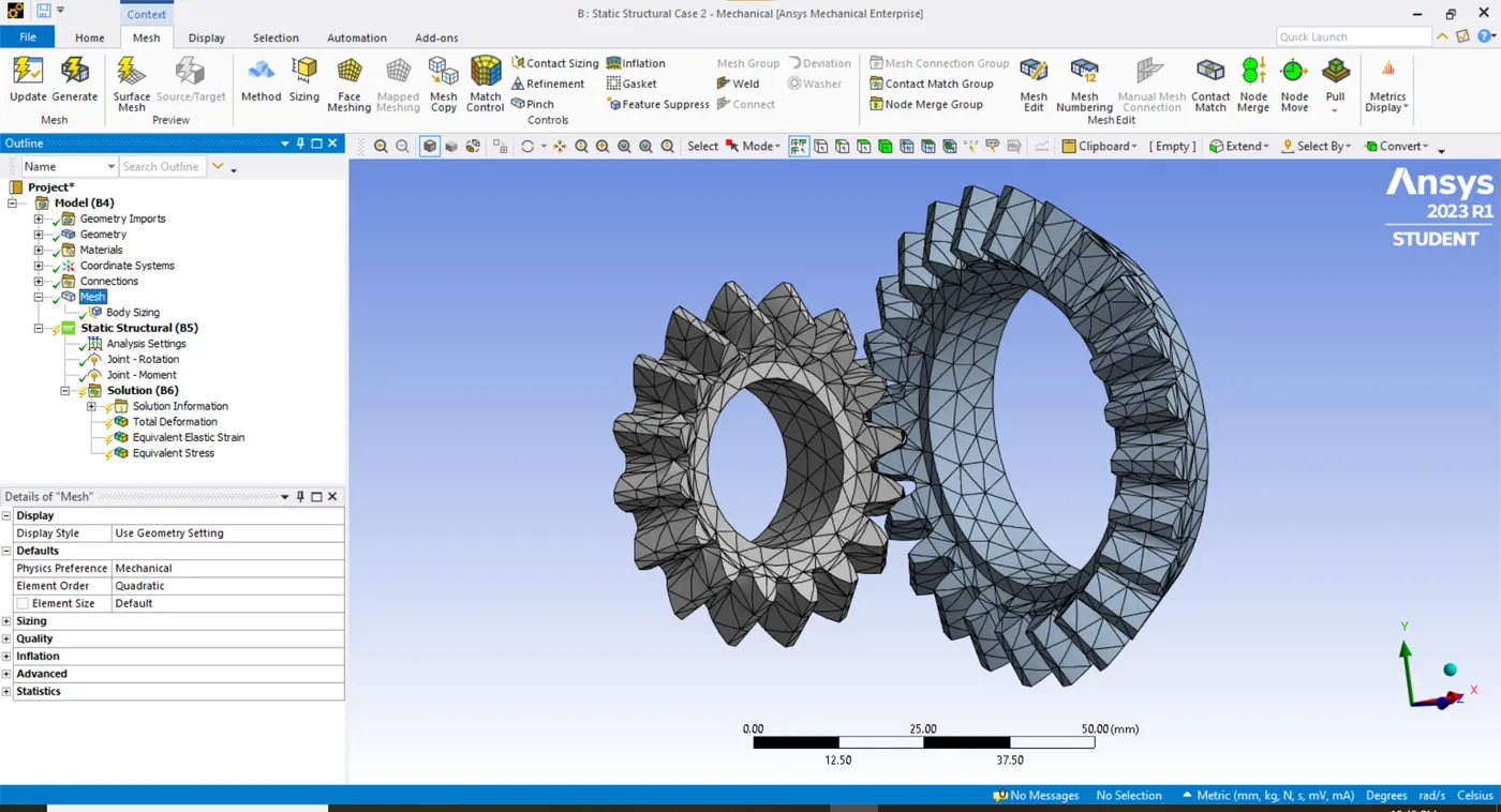
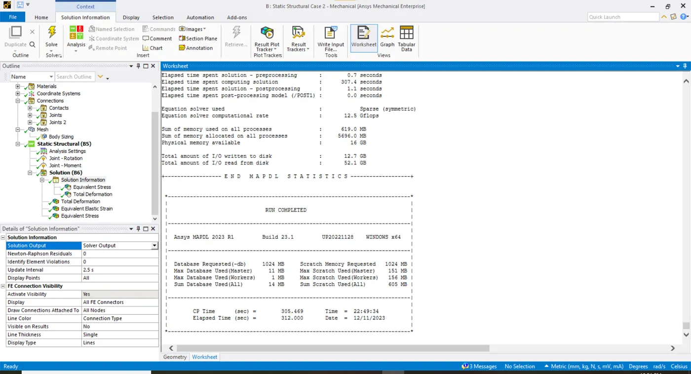
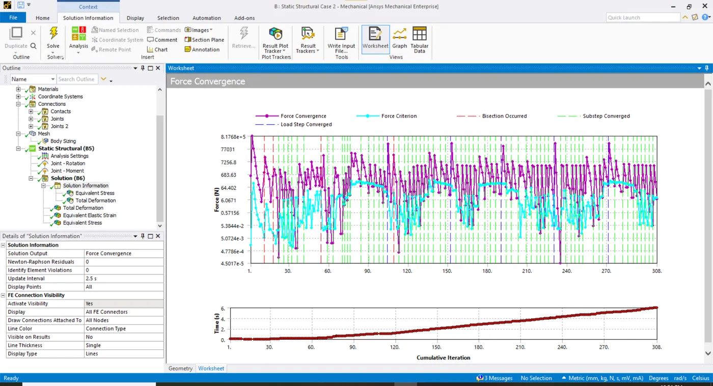
- In case 2 a duplicate system of Case 1 is created with everything similar except the mesh size. The mesh size in this case inputted is 5mm.
CASE 3
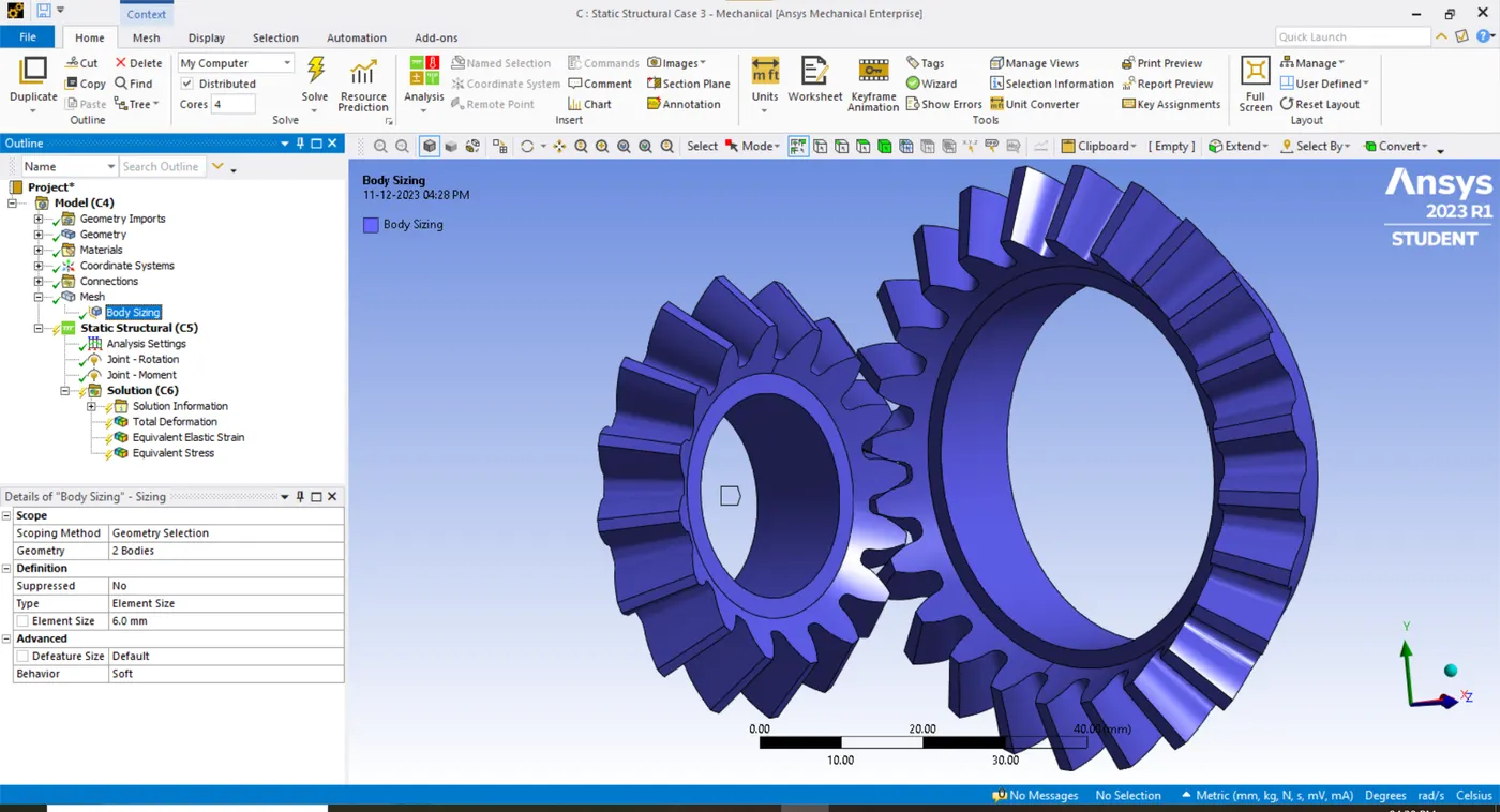
- In case 3 a duplicate system of Case 2 is created with everything similar except the mesh size. The mesh size in this case inputted is 6mm.
RESULTS
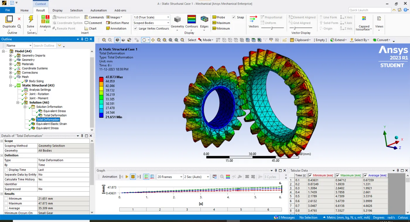
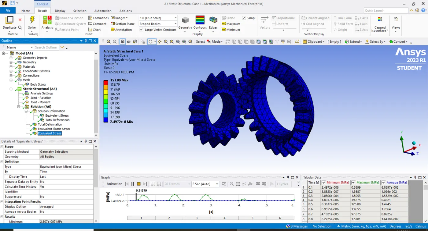
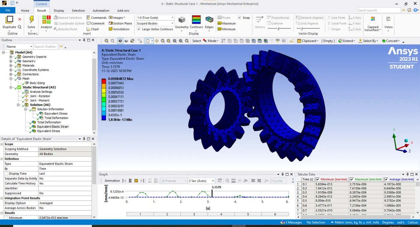
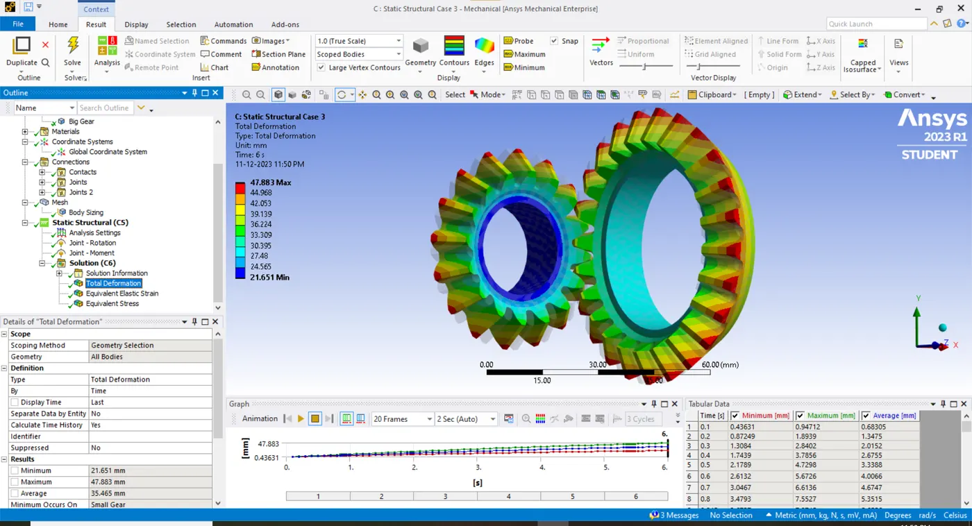
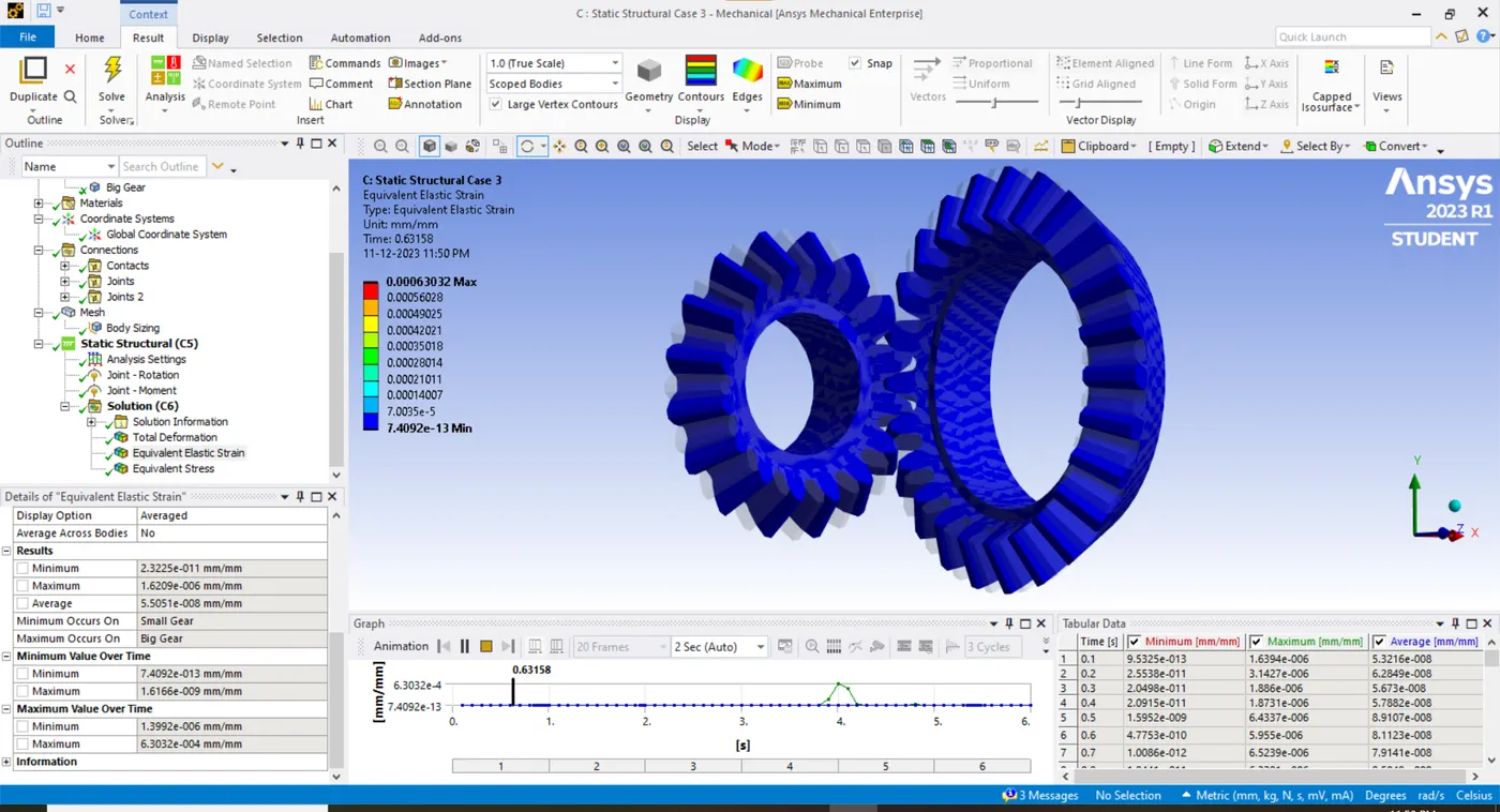
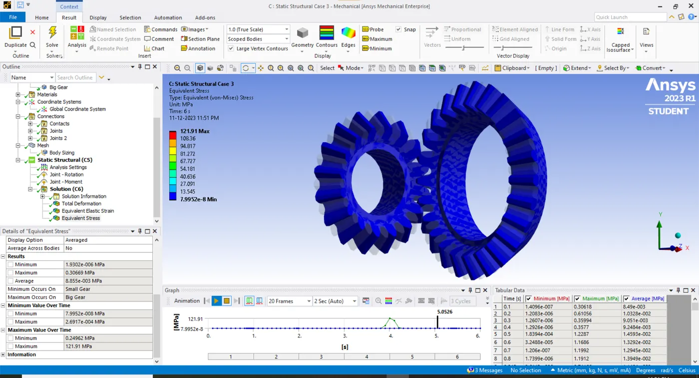
CASE 1
CASE 2
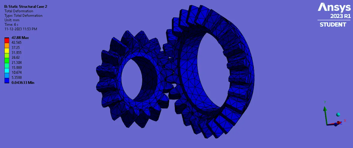
CASE 3
GRID DEPENDENCY TEST
CONCLUSION
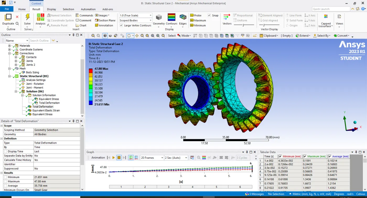
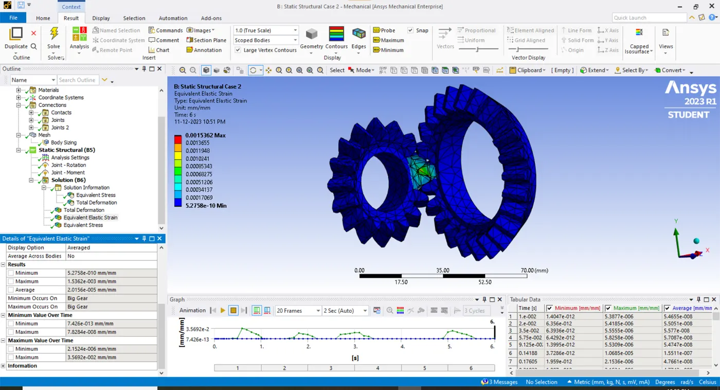
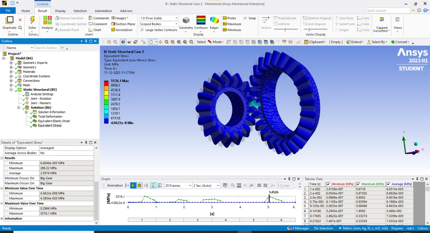
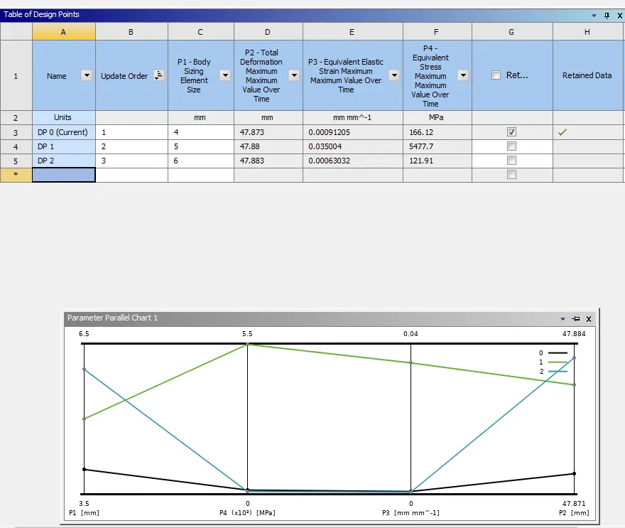
- The stress and strain values for Case 1 and Case 3 are below the yield strength. But in Case 2 the stress and strain is way too high which can't be accepted according to FEA standards.
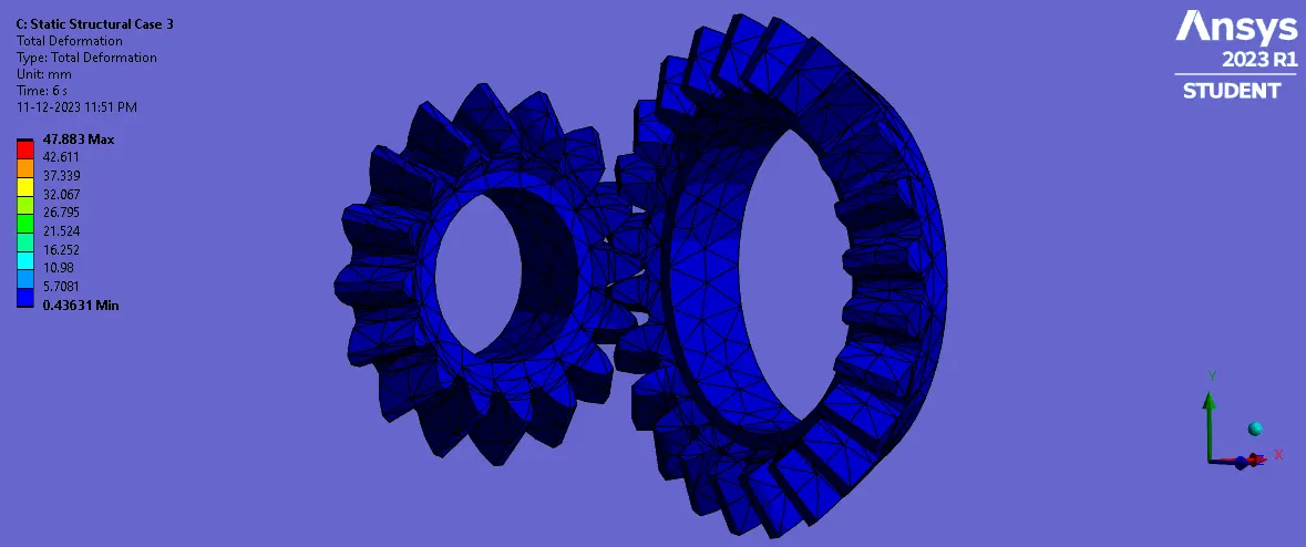
- The deformation for all three cases is likewise with a negligible difference.
- The grid dependency test is achieved eventually by using a parameter set and design points table in the ANSYS workbench.
- The time step size is modified to the mesh size used in all the cases respectively.