Week - 3 Drop test Challenge
DROP TEST USING LS-DYNA
INTRODUCTION
For this project, we give you a file with only nodes and components for two sections, a scaled-down telephone, and a plate that simulates ground.
- We expect you to construct a proper, hard wall or a solid, ground-like surface ( as shown in the lecture )
- To execute a drop test, you must first use this to produce a complete simulation file.
- The *INITIAL VELOCITY card should be used to specify the cellphone's speed requirements.
We are just interested in the time between the impact and a few milliseconds after it occurs, not in how the phone moves from your hand to the plate. As a result, we'll maintain a tight distance between the two sections and use a suitable magnitude of velocity.
For this assignment, we will analyze the direction of the phone hit such that the length of the phone is perpendicular to the impacting surface. The orientation of the mobile phone is also significant, and there are precise instructions on how to orient the items.
Create a complete input file for a drop test using your discretion, the manuals, and the previously displayed simulations based on what you have learned thus far.
AIM
The goal of this task is to develop a feel for generating an input deck from scratch and producing outcomes akin to one of the following situations, not to create a perfect replica. i.e.
- After impact, the phone ought to rebound in the same direction.
- Bounce back after the hit while rotating.
EXPLANATION
- To begin with, we import the model provided in .k(keyword) format into LS-Dyna. Once imported we examine it and study its physics keenly to do action furthermore. We observe 3 PIDs in the assembly deck i.e solid cellphone, shell floor, and solid floor.
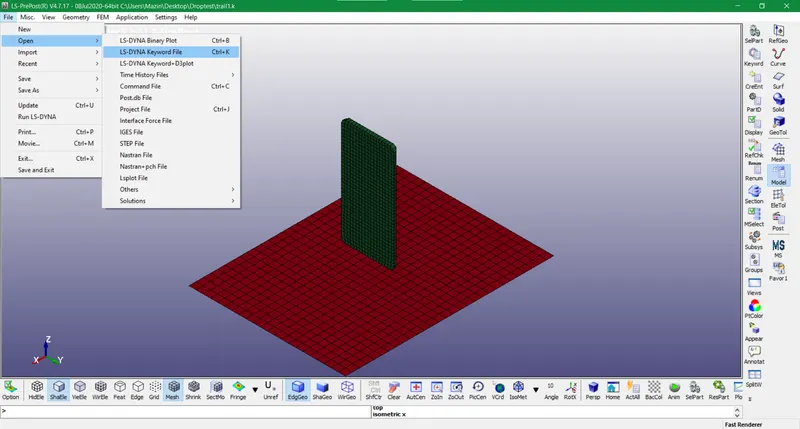
Figure-1 Pre-processing File imported in LS-Dyna
- After that, we use the conversion factor of kg m s for solving using a consistent units table for LS-DYNA. Also, we choose several keywords sequentially in the Model and part tool by selecting keywrd option. First, we will give material property to the PIDs and distinguish them in different sections by allotting SIDs. We choose steel for the floor and cell phone and input the respective values. We developed MAT Keyword for elastic and rigid with two MIDs.
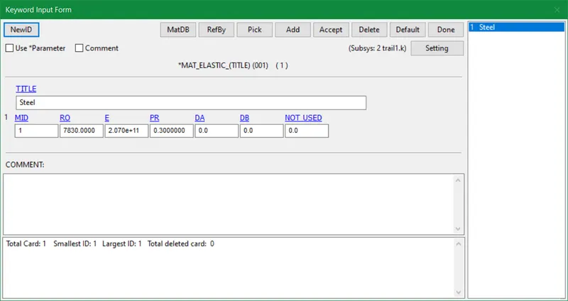
Figure 2 Material Elastic card
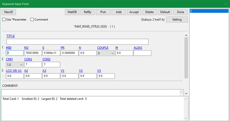
Figure-3 Material Rigid card
- In addition to this, we create the PART keyword by forming different PIDS of different components in order to distinguish them while pre-processing.
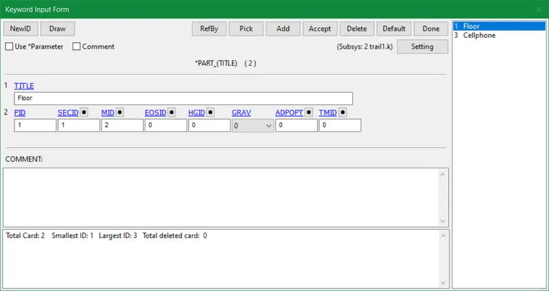
Figure-4 PART ID card
- Also, enter SECTION type whether shell or solid and element formulation w.r.t the PID examined in the model. We represented the shell as a floor and the solid as a cell phone by mentioning the SECID.
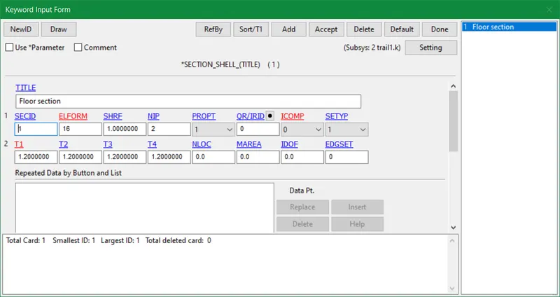
Figure-5 SECTION Shell card
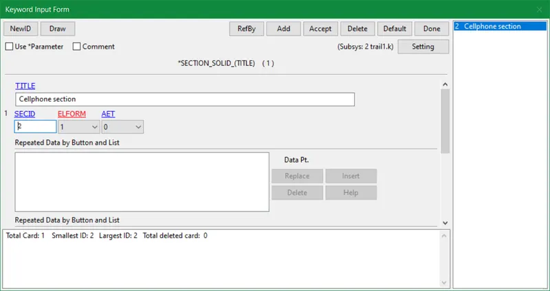
Figure-6 SECTION Solid card
- Now we will provide contact between the parts or PIDs like we use automatic surface-to-surface contact in this case. In order to stop model components from passing through (or separating from) one another, contacts are surfaces created from already existing nodes and elements.
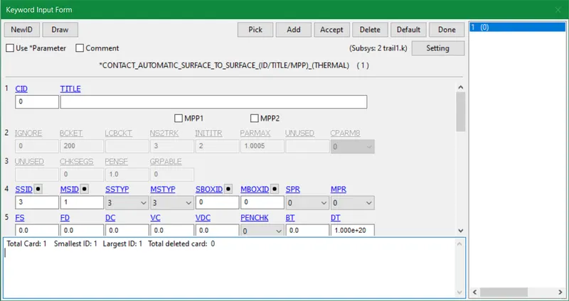
Figure-7 CONTACT card
- Initial velocity is introduced at a particular node ID where prescribed motion comes into play with a specific coordinate axis. Here we used the Z axis in a negative direction with a respective value.
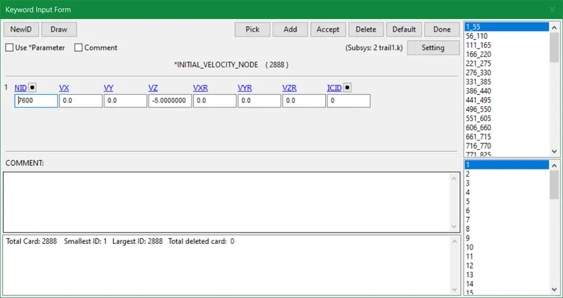
Figure-8 Initial velocity card
- Lastly, we modify hourglass control whose purpose is to make sure that rigid body rotations are orthogonal to all elements of the hourglass force vector. Nevertheless, update the termination time as well in the Control keyword for post-processing. Finally, save the database as a binary d3plot file which is used for post-processing.
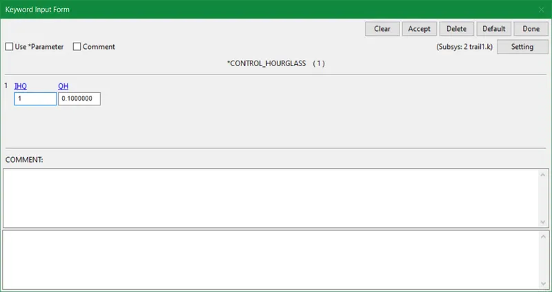
Figure-9 CONTROL Hourglass card
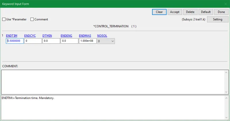
Figure-10 CONTROL Termination card
- After updating all keyword parameters we run the binary d3plot file in File>Run LS-DYNA menu bar. LS-Run takes the input file and inbuilt solver and starts the processing into an animation to obtain stress, strain, and other physical quantities needed for the required analysis.
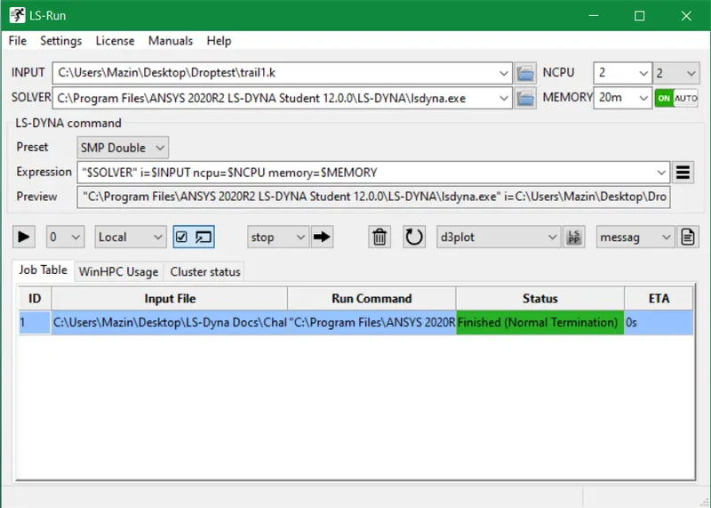
Figure-11 LS-Run
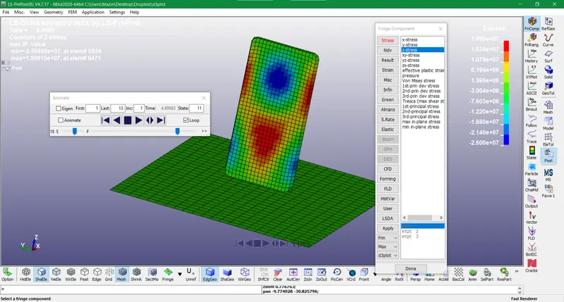
Figure-12 Post-processing file
CONCLUSION
- This assignment provided us with a better understanding of using solving parameters to extract a post-processing database.
- The initial velocity and termination time portrayed real practical results for the analysis used in this file.
- The sequential pattern of updating keywords gave a better presentation of how post-processing works and the ways to modify it according to the physics of the problem.
- Nevertheless, this assignment gives us a better outlook on how LS-Dyna software works basically by simple means.