Week 9-Creation of 1D Connectors Challenge
Establishing Connections in Hyper mesh
INTRODUCTION
The majority of constructions have some kind of jointing or connecting. It is almost as old as the introduction of bronze and subsequently iron into an early civilization where rivets were used to join structural plates. With the development of screw-cutting techniques, bolted connections became feasible, and utilization was expedited by, among other things, pitch and thread uniformity. Even today, hundreds of bolts and rivets are still used to join the parts of constructed constructions like ships and aeroplanes. Spot welding and welding are other technologies used for large-scale connections. The use of bonding has significantly increased as a result of advancements in adhesive technology and the widespread use of composite materials. Continuous connections are possible in places like the broad surface areas of plates, flanges, and other abutments. As an alternative, lugs and pins, clips, or similar connections may be used to create independent load routes. When attempting to model such connections and joints within a finite element analysis, the engineer is presented with a challenging choice (FEA). If an overall stiffness or strength assessment is to be done and the connection is presumed to be sufficiently continuous, it is frequently possible to overlook the specifics of each particular connection.
OBJECTIVES
For this assignment, you will have to mesh the given geometry provided with the quality parameters.
Create a connector and attach the various parts of the given model
- Right_Rail_2 & Front_truss_1:- Seam-Quad(angled+capped+L)
- Left_Rail_2 & Front_truss_1:- Quad elements
- Front_truss_2, Front_truss_1 & Right_Rail_1:- Spot weldwith 2 Layers and 5 mm Diameter
- Front_truss_2, Front_truss_1 & Left_Rail_1:- Hexa (Adhesive)
- Rear_truss_2 & Right_Rail_2:- Bolt Connector
- Rear_truss_2 & Left_Rail_2:- Bolt Connector
- Right_Rail_1 & Right_Rail_2:- Spot-weld with Rigid Elements
- Left_Rail_1 & Left_Rail_2:- Spot-weld with Spring Elements
- Rest all the components left Join them with suitable connectors
PROCEDURE
- The model of frame assembly is imported using the import model option as the file is in .hm format. The geometry looks fine and easy to work upon as it is a sheet metal component so we develop the mesh with the quality parameters issued to us.
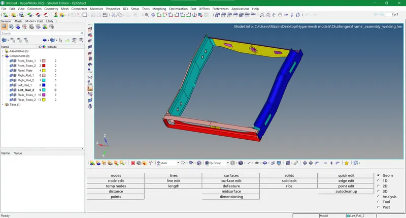
Figure-1 Import the geometry into hyper mesh
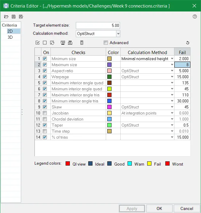
Figure-2 Criteria file parameters
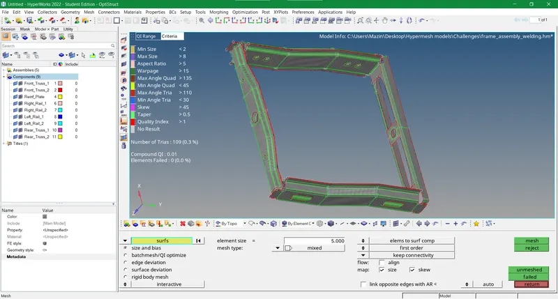
Figure-3 Optimum quality mesh produced on the component
- Once the meshing is complete with the optimum quality we establish connections as per the data instructed. The first connection is of seam weld generated between the mentioned surfaces with a seam type as a quad(angled+capped+L) which can be opened using this pathway viz. 2D>Connectors>Seam. We select the nodes on the edge of the top plate and choose both components for the creation of the seam weld. If the connector line is green it means the connection is realized otherwise if it is red then it means the connection between the weld and the base surface has not been established. The error can be due to a varied number of reasons like lower search tolerance or non-aligned elements of both surfaces. So we can check the information of the connection generated in the connectors panel that can be opened via this pathway View>Browsers>Hypermesh>Connector. We can realize/unrealize the specific connector in the aforementioned panel and modify its parameters accordingly.
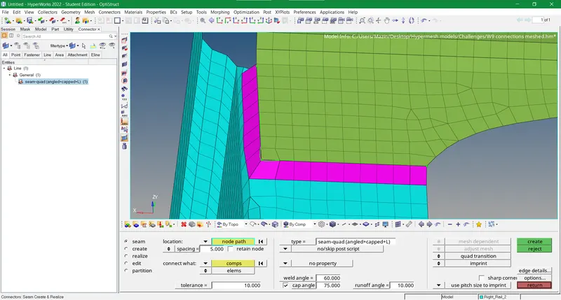
Figure-4 First connection of Seam-Quad(angled+capped+L) formed
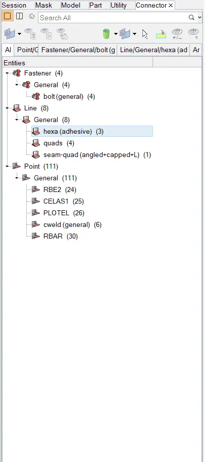
Figure-5 Connectors panel
- Likewise, we proceed with 2nd connection with a seam type of quads and generate it by the same method. We can also get an overview of the connector report by knowing the status of our connectors. Red/yellow/green displays the connection status where yellow means unrealized and the rest of the two were already discussed before. We can modify the connection parameters in unrealized status and realize it afterwards.
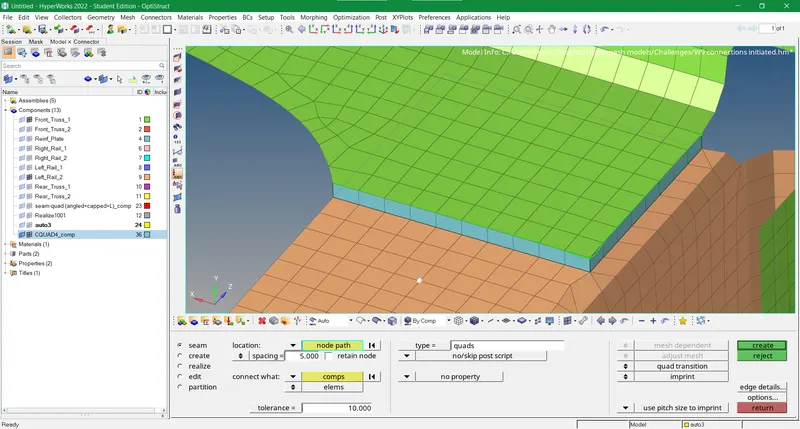
Figure-6 Second connection of Seam(Quad elements) formed
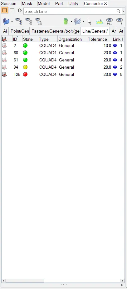
Figure-7 Connections status and details
- For 3rd connection spot weld, we choose the same method except for the seam we choose a spot in the connector’s sub-panel of the 2D panel. For the 4th connection, we choose Hexa adhesive as seam type for seam weld. For the 5th and 6th connections, we choose the bolt option in the connector’s sub-panel of the 2D panel. However, there is no hole between the parent surface and the base surface so we choose an option from “consider existing hole only” to “create a hole if none” and select bolt type as Bolt (General) or Bolt (CBAR). For the 7th and 8th connection, we again use spot weld but with different spot types as instructed. For the rest of the connections, we use a variety of connectors as per the element configuration of two components. Lastly, we inspect it and analyze it by using attach option to check the integrity of all connections between all components.
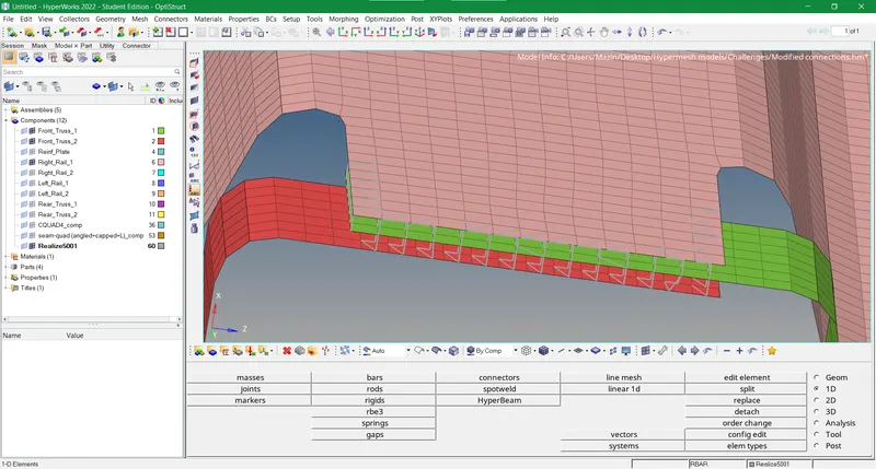
Figure-8 Third connection of Spot weld created
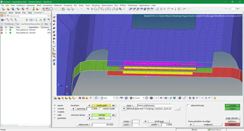
Figure-9 Fourth connection of seam Hexa (adhesive) generated
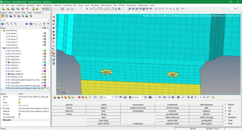
Figure-10 Fifth connection of bolt connector developed
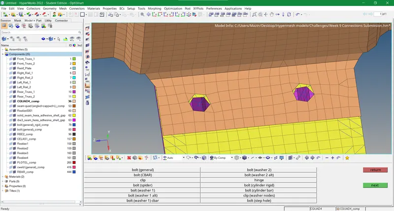
Figure-11 Sixth connection of another bolt connector produced
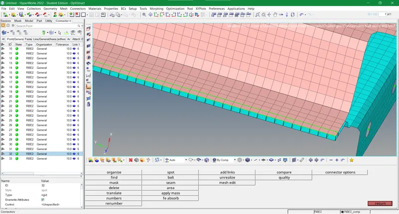
Figure-12 Seventh connection of Spot weld with rigid elements conceived
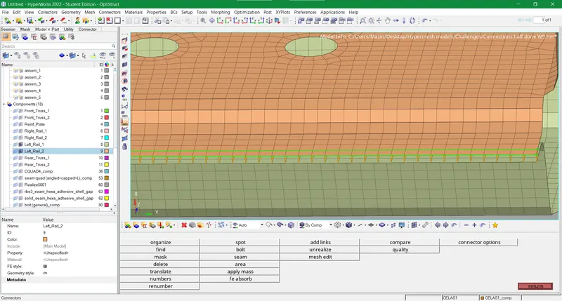
Figure-13 Eighth connection of spot weld with spring elements generated
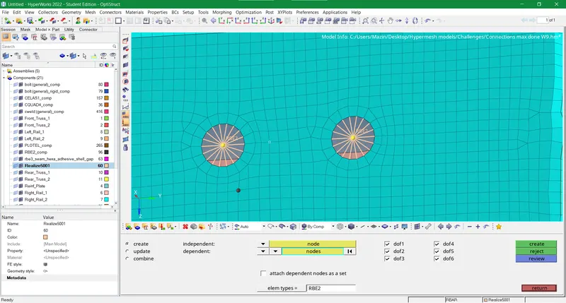
Figure-14 Rigid body elements 2 constructed
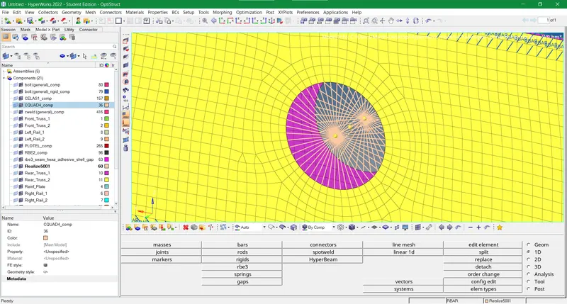
Figure-13 RBE2 connections between two symmetrical colinear holes
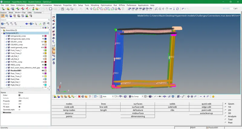
Figure-14 Final image of the model incorporated with connections
RESULTS
- We evaluated the pre-processing of FEA by knowing its final step which is the establishment of connections between different components of the model.
- Seam weld, spot weld and bolt connection with different types endorsed a proper layout of energy distribution in the mesh.
- Rigid body elements in almost all connectors presented a better overview for checking the mechanical values for different entities w.r.t nature of the material.
- Nevertheless, connections for this model are developed with the aid of either 1D or 2D connectors in the hyper mesh.