Week 3 - 2D meshing for sheet metal
The Bi-dimensional meshing of the hood of the car using ANSA
INTRODUCTION
The hood is a key component of a car's front end, and it serves a variety of functions. In hood assembly design, there are four main parts: outer panel, interior panel, latch system, and hinge system shown in Figure 1. The style department's exterior panel skin surface has a proper aesthetic look, gap, and falseness. The aerodynamic criteria apply to the outer hood panel. In hood design, the hood inner is the most important functional component. It's the most difficult and time-consuming aspect of the hood construction. The hood inner was intended to fulfil the normal load scenarios during vehicle development. All cars, trucks, and other vehicles require a hood latch system. This system connects the hood assembly to the vehicle body. When the hood is open or closed, the hinges also guide and hold it in place. Their kinematics analysis had been completed to guarantee that the hood did not come into touch with any other components.
OBJECTIVE
There are various phases involved in completing this process which are as follows:
- Cleaning up all geometric errors for whole hood assembly using specific tools in Topo Deck.
- Assigning thickness and then extracting the mid-surface of all entities that are incorporated in the hood assembly required for meshing.
- Inserting given data in quality criteria and mesh parameters.
- Proceed with meshing following five thumb rules w.r.t the type of analysis and given parameters.
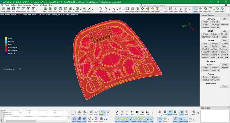
Figure 1 Hood of the car (Metal sheet assembly)
PROCEDURE
The whole process is divided into a number of stages which are put in sequence as follows:
- We start by inspecting and analysing the model in order to make it easier to work with. While going through the entities of this sheet metal component we found that it is divided into four parts viz. The outer panel of the hood, Inner panel of the hood, Latch and Hinges (Left and Right). Henceforth we will clean all the geometrical errors of the whole model before proceeding further. After doing a geometrical check-up we come across a lot of errors shown below in Figure 2 by using the checks manager in ANSA.
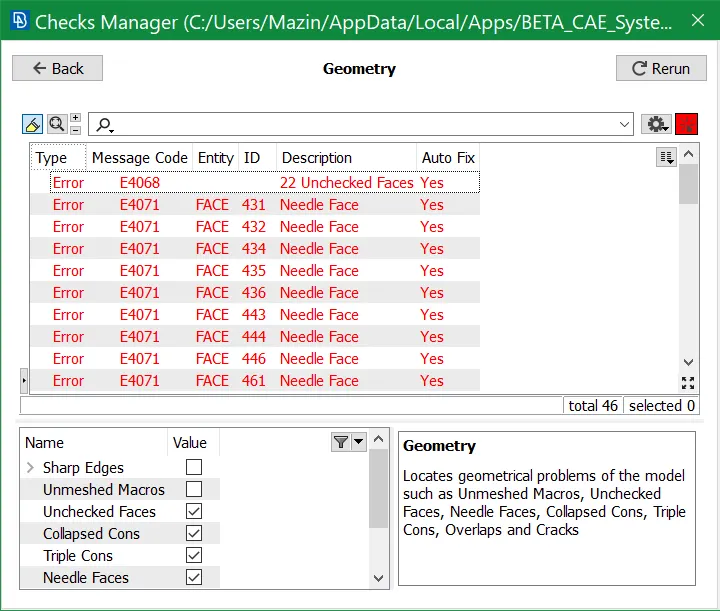
Figure 2 Geometrical Errors Check up
- There are numerous errors in the CAD model of the hood that needed to be rectified before advancing for meshing. Many needle faces are found in certain areas of the hood model that are fixed accordingly with options like Cons>Fill hole and Faces>New in Topo deck shown in Figure 3. Also, triple cons are corrected by Cons>Release cons and Faces>Topo in the Topo deck in this model. We can use the auto-fix option in the checks manager as well to fix all errors automatically. After correcting all errors we rerun the checks manager and we will get a 100% result of error-free geometry shown in figure 4.
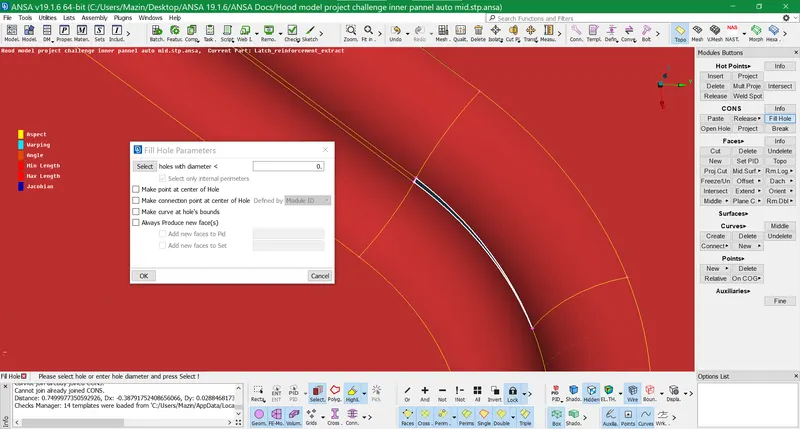
Figure 3 Needle faces corrected
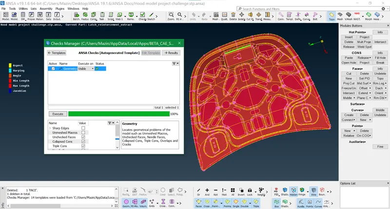
Figure 4 All geometrical errors are removed
- Now we will start with the extraction of mid surface for all 4 entities of the model. There is quite a number of methods to do so but I preferred the Faces>Offset option in the topo deck using respective thickness shown briefly in Figures 5,6,7 and 8.
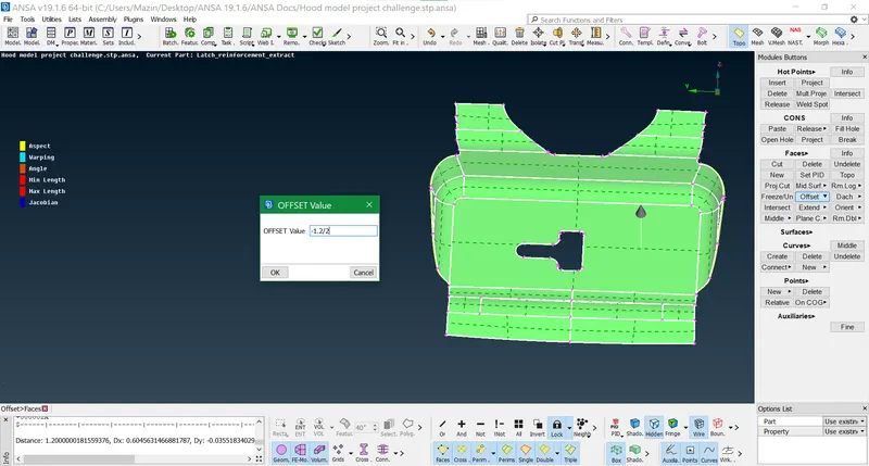
Figure 5 Extracting mid-surface for latch part
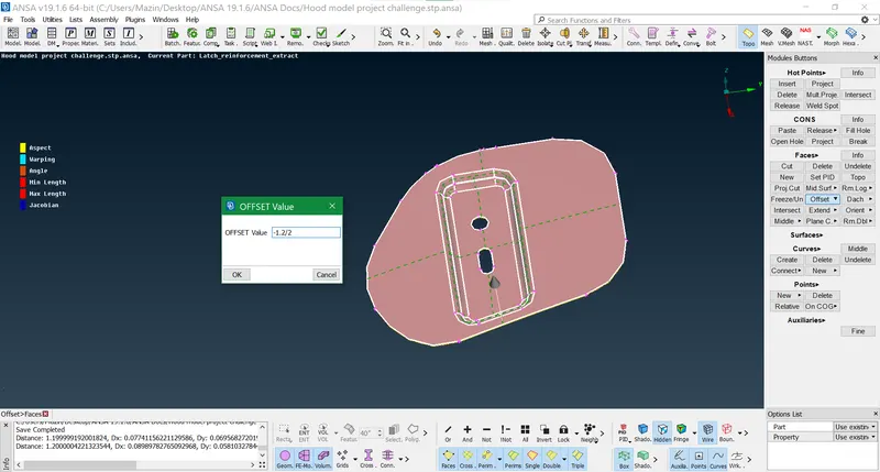
Figure 6 Extracting mid-surface for hinge part
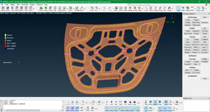
Figure 7 Extracting mid-surface for the inner panel
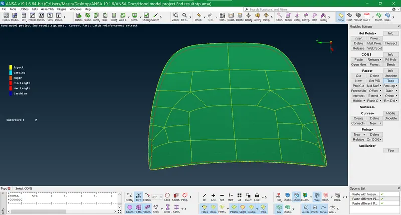
Figure 7 Extracting mid-surface for the outer panel
- We'll proceed to the thickness modification of the entire model and set PIDs, which assign properties to faces or groups of entities all at once, now that we've completed the extraction of mid-surfaces. Figure 9 gives a detailed outlook of PIDs assigned to all entities. Figures 10 and 11 demonstrate how the model's thickness has changed. We change the thickness in the mesh deck by selecting the Perimeters>Length>Perimeters & Macros option one by one and entering the specific quantity.
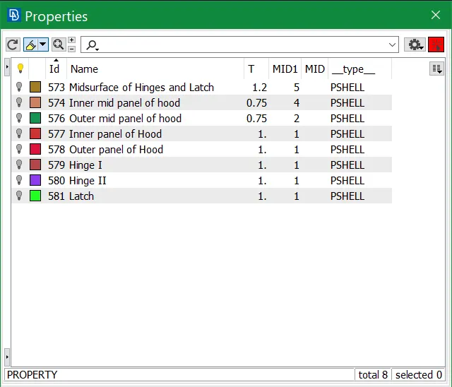
Figure 9 Set PIDs to all entities in the geometry
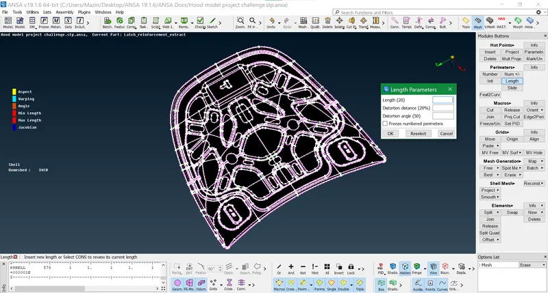
Figure 10 Before Thickness modification
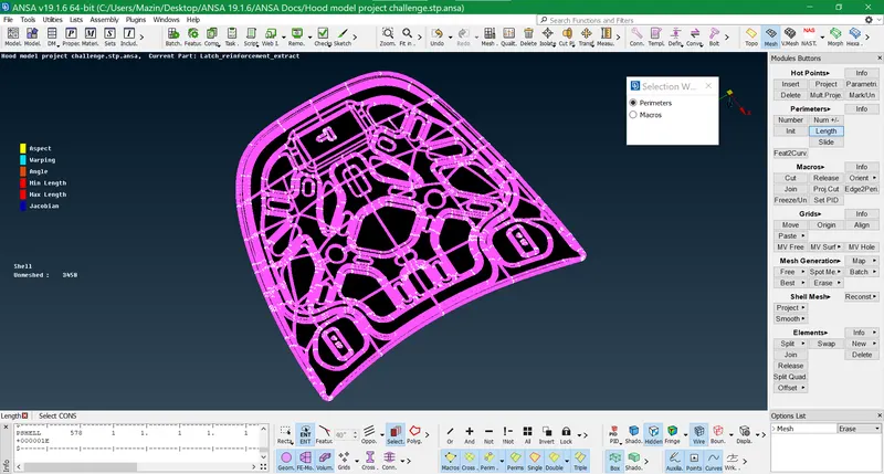
Figure 11 After Thickness modification
- Well before we enter the quality parameters and mesh parameters w.r.t the quality criteria given let us discuss the main feature that is found in the outer panel of the hood i.e. hemming. Hemming is a sort of adjustment panel attachment that joins the inner and outer closure panels together. It's done by wrapping the outer panel's flange over the inner panel. These are found in doors, tailgates, and hoods, among other places. The hemming is addressed to avoid the average thickness failure of the entity for meshing. It is shown in figure 12 that the model fails w.r.t minimum or average thickness provided in quality criteria. In Figure 13 we toggle the outer construction lines by joining them in the Topo deck with the Faces>Cut option. The average thickness of 5 pertaining to quality criteria thus gives recognition for good meshing.
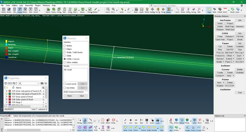
Figure 12 Thickness failure on edges of the outer panel of the hood
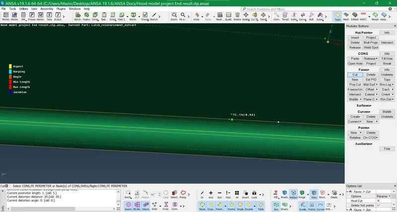
Figure 13 Hemming Process
- It is time to input data for the quality criteria and mesh parameters given which are briefly displayed in figures 14 and 15. After that, we will commence with the meshing of all entities gradually.
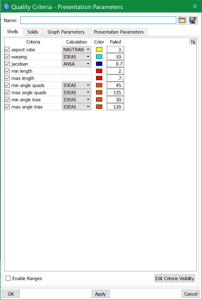
Figure 14 Quality Criteria
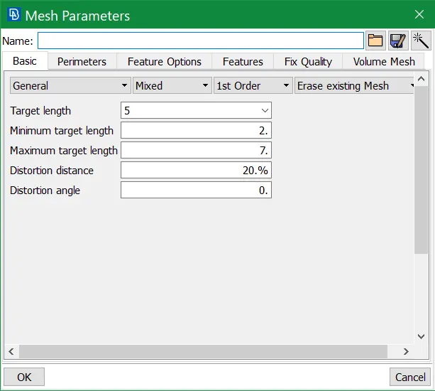
Figure 15 Assigning Mesh parameters
- We will go with free mesh, best mesh, batch mesh or spot mesh options in the mesh deck for meshing according to our convenience and model design or specifications. During meshing, we need to reckon to eliminate rotating quads and minimise tria’s w.r.t quality criteria. Also need to follow 5 thumb rules in order to attain good mesh flow. The meshing of the latch and hinge parts is portrayed in Figures 16 and 17.
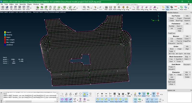
Figure 16 Latch part meshed
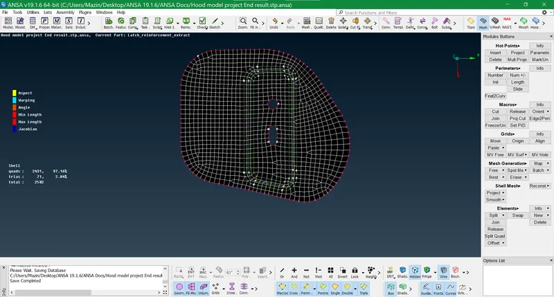
Figure 17 Hinge part meshed
- The major parts left are the inner panel and outer panel that we are meshing gradually by taking one symmetrical half and then using the symmetry option to cover another symmetrical half. Symmetry is briefly displayed orderly in figures 18, 19 and 20 by selecting the Transfer icon in the utility bar. We can either use the default symmetry plane or the Mirror 3 point plane option to do symmetry w.r.t the design and shape of the entity.
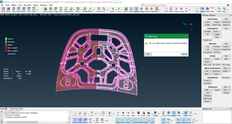
Figure 18 Inner panel symmetry operation step I
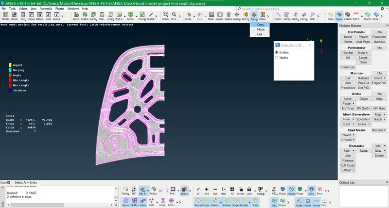
Figure 19 Symmetry operation step II
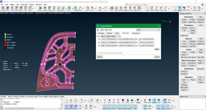
Figure 20 Symmetry operation step III
- The mesh is apparently displayed for outer and inner panels after symmetry operation in various views in Figures 21,22,23 and 24.
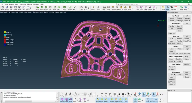
Figure 21 Inner Panel mesh completed
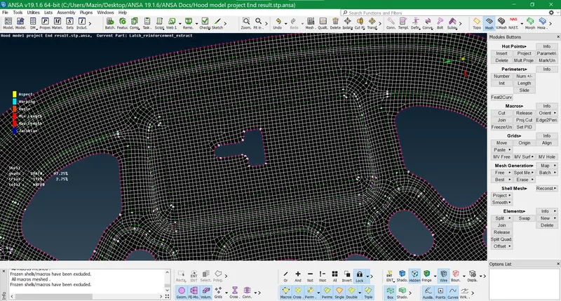
Figure 22 Inner panel in zoom view showing latch part
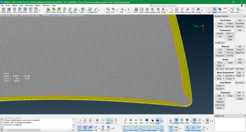
Figure 23 Outer panel zoom view
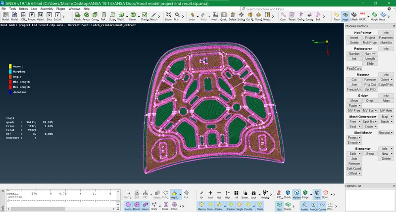
Figure 24 Hood Assembly Completed
LEARNING OUTCOMES
- The intricate design of hood assembly provided a new kind of experience for the removal of triple cons and rectifying other geometrical errors like needle faces and filling gaps to a major extent.
- The hemming is a new feature that’s being entertained in this model that specifically refers to the quality criteria essentially onto the outer edges or flange of the outer panel. Toggle on and off clarifies the average thickness corresponding to the good mesh of the outer panel.
- The meshing at a larger level in this model on fillets and veins of the inner panel provided a better opportunity to tackle rough challenges apparently. A vivid transition is done to choose a specific type of meshing for a significant design model. Some tria’s are important in certain areas so they are not altered otherwise it changes the whole configuration of mesh flow.
- Nevertheless, this model gave an ample example of using ANSA as an FEA tool for sheet metal.
CONCLUSION
- Cleaned up all geometric errors for whole hood assembly thoroughly and rechecked again after meshing to get optimum results.
- Assigned the designated thickness for the hood assembly and extracted mid surfaces for each entity.
- Quality criteria entered are within the prescribed values and standards of the model.
- Since it was crash analysis so followed the 5 thumb rules of meshing accordingly and achieved a good mesh flow for all entities without any quality issues.