Week 8-3D Tetra Meshing Challenge
3D Tetra Meshing in Hypermesh
INTRODUCTION
Four tria faces and four nodes make up a 3D tetra element. The primary characteristic of a tetra element to be examined is its height. A tetrahedral element mesh can be created using one of two methods offered by Hyper Mesh. Without further input from you, the volume tetra mesher automatically creates a tetrahedral mesh by working with surface or solid geometry. This technique frequently produces a high-quality tetra mesh quickly and effortlessly, even with complex geometry. In order to manipulate the resulting tetrahedral mesh, the typical tetra mesher first requires a surface mesh made up of tria or quad components as input. This provides a lot of control over the tetrahedral mesh and the ability to create one for even the most complicated objects. The Tetramesh panel can be used to insert first- or second-order tetrahedral elements into a closed volume. If a shell mesh (tria or quad elements) completely encircles a region, with each element having material on one side and open space on the other, the region is said to be contained.
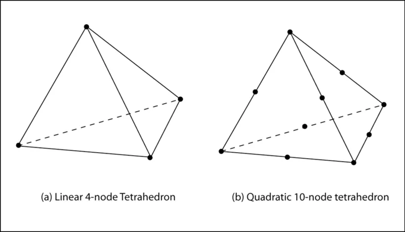
Figure-1 Typical image of 3D tetra element(First and 2nd order)
OBJECTIVES
Create a Teramesh for Housing component with the following quality criteria.
TetraMesh Generation Method: 2D to 3D Conversion
Elements sizes: Min- 2 Units, Target- 5 Units, Max- 7 Units
Tet collapse: 0.15
Model-1 (Housing Model)
For the given model, Create a 3D Tetramesh with the following quality criteria.
TetraMesh Generation Method: Quick Tetra Mesh/ Volume Tetra Mesh
Target Element size: 3 Units.
Tet Collapse: 0.15
For the given assembly model, Create a 3D Tetramesh with the following quality criteria.
TetraMesh Generation Method: Quick Tetra Mesh/ Volume Tetra Mesh
Target Element size: 4 Units.
Tet Collapse: 0.15
PROCEDURE
Model 1:
- We pursued importing the housing model into the hypermesh and start analyzing it for further processing. As we have to use 2D mesh first so we will delete unnecessary solid parts pre-attached to the hub component of the model. Without further ado, we commence with manual geometric clean-up to avoid minimum length quality criteria issues. The salient feature of 2D to 3D conversion meshing is that we reckon only min and max length quality parameters. However, a new parameter known as tet collapse is to be recognized for 3D tetra meshing in this assessment.
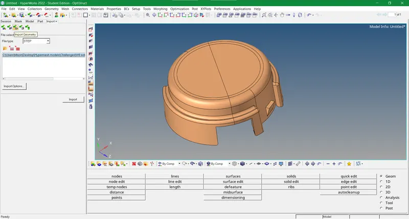
Figure-1 Import geometry of Model 1 in the hypermesh
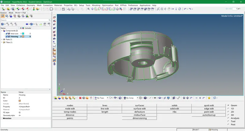
Figure-2 Start manual geometric clean-up on Model 1
- Since the manual geo clean-up of the whole model is completed, we embark forward by doing 2D meshing on the original geometry with the prescribed data of criteria and parameters file. After fixing some quality issues for minimum and maximum element length parameters we start the 3D mesh generation. For 3D we go to the tetra mesh sub-panel in the 3D panel of the tools bar and change the mesh type from mixed to tria. As the type of elements used are tetrahedrons and not Hexa's so tria’s are taken into account for this assessment. Further ahead fixing all quality issues pertaining to tet collapse our model is processed.
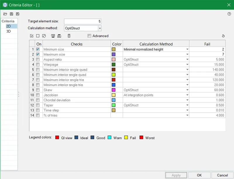
Figure-3 Criteria file with only min and max length values for 2D meshing
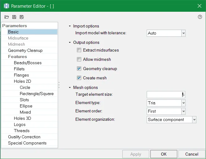
Figure-4 Parameter file editor
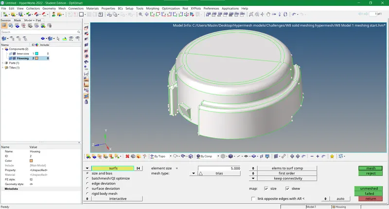
Figure-5 2D meshing with tria's in mesh type
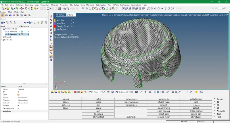
Figure-6 2D meshing of the housing component
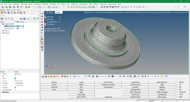
Figure-7 2D meshing of hub component
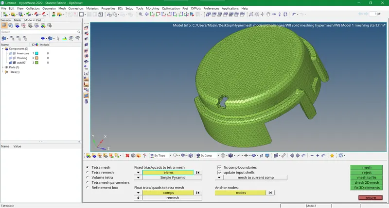
Figure-8 3D tetra meshing of housing component sectioned on the top fillet
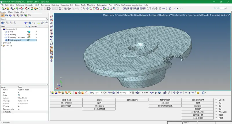
Figure-9 3D tetra meshing of hub component sectioned on the plate edge
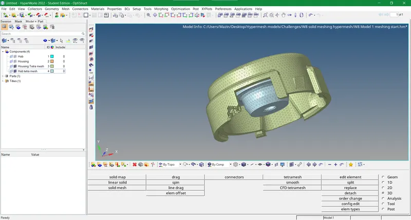
Figure-10 Final image of the 3D model generated
Model 2:
- In model 2 we need to use directly 3D tetra mesh on the component by using the quick tetra mesh method or volume tetra mesh method. Henceforth we imported the model by import geometry option as the respective file is in .IGES format.
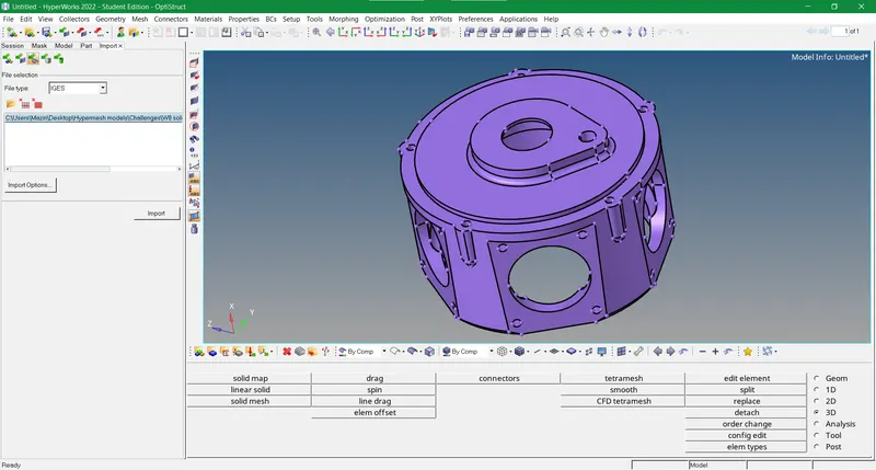
Figure-11 Import geometry of Model 2 in hypermesh
- We attempted the former method by choosing this pathway in the menu bar at the top View>Browsers>Hypermesh>Utility>Geom/Mesh>Mesh Tools>Quick tetra mesh. Putting down the prescribed data in the quick tetra mesh panel we initiated the 3D mesh. The quick tetra mesh is an automated method to do auto geometric clean-up on the component and mesh it accordingly. We achieve both 2D mesh on the component surface and 3D mesh separately with this method. The quality of the mesh is not reckoned in either the quick tetra mesh or volume tetra mesh method. It is a very fast process so recommended for quick results where time is not constrained.
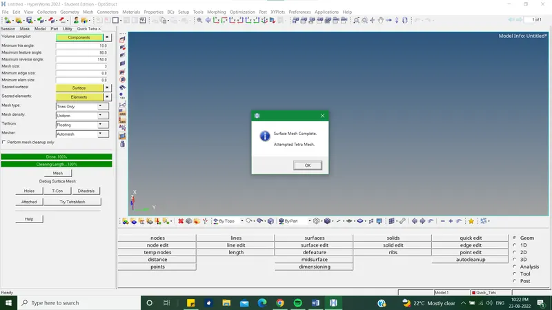
Figure-12 Quick tetra mesh method used on Model 2
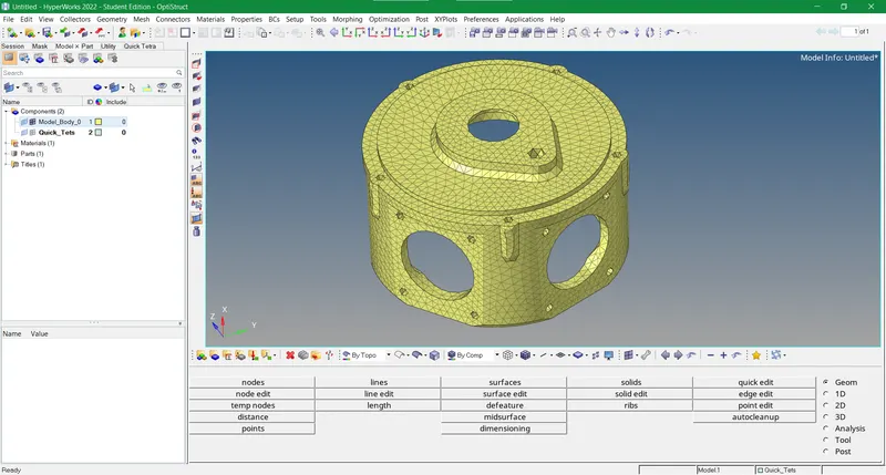
Figure-13 2D mesh generated on the surface of the model by quick tetra mesh method
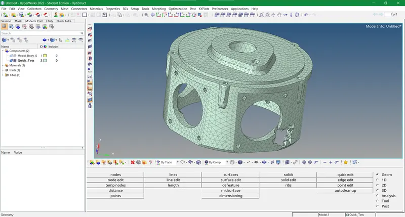
Figure-14 Final image of the 3D tetra meshed model sectioned on the lower side
Model 3:
- In this Model (Turbocharger) we approached with a blend of both operations due to improper geometry. Many closed volumes were missing in this model which was divided into 4 components viz. Casing, Hub, Supporting plate and Holder housing. The quick tetra mesh method failed in the beginning for supporting plate and hub and so did the volume tetra mesh method. The mesh type for both of them was generated in the form of quads and the associativity of 3D elements on the rest of the two components was failing as well. Although we did manual geometric clean-up and tried the quick tetra mesh and volume tetra mesh method evenly for all components. After a few trials, we achieved good results w.r.t the assigned data and mesh type.
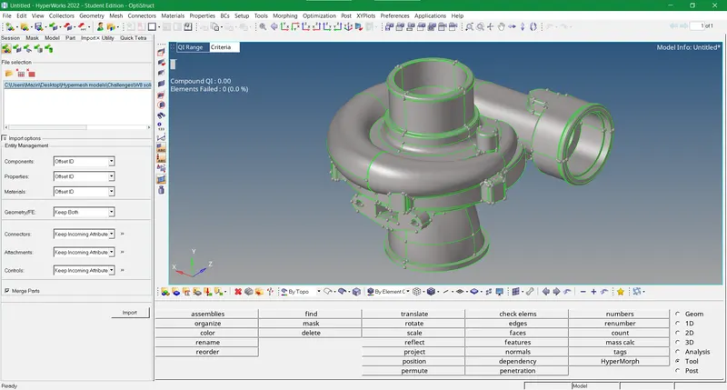
Figure-15 Import geometry of Model 3 into the hypermesh
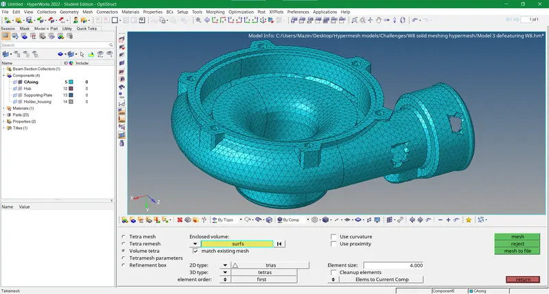
Figure-16 Casing 3D meshed using volume tetra mesh method
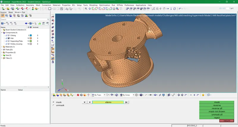
Figure-17 Hub 3D meshed using volume tetra mesh method
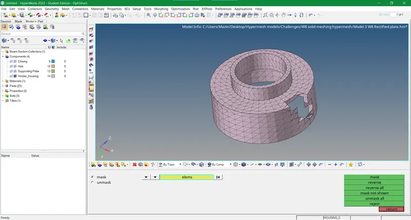
Figure-18 Holder housing 3D meshed using a blend of methods to achieve tetrahedrons on the component
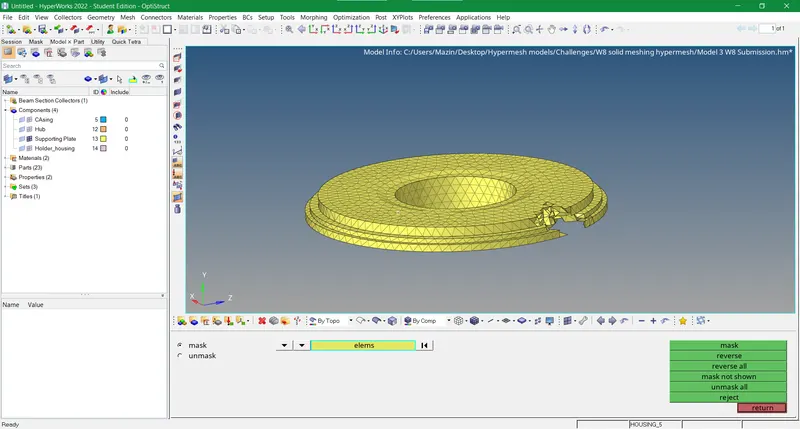
Figure-19 Support plate worked upon with manual geometric cleanup and then 3D meshed using quick tetra mesh method.
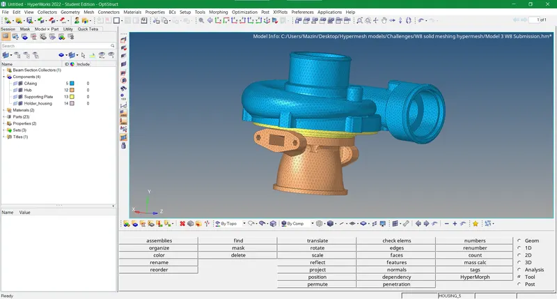
Figure-20 Final image of 3D meshed Model 3
RESULTS
- We performed 3D meshing in all the 3 models of this assignment and achieved good results.
- We used the manual 2D to 3D conversion method which gave a better insight into 3D modelling using hypermesh
- Quick tetra and volume tetra mesh provided a better perspective of using 3D mesh w.r.t different configurations.
- Tet collapse is a new quality parameter that comes into play for 3D meshing whilst the rest of the quality parameters are ignored.