Week - 4 - 2D meshing for Plastic components
BI-DIMENSIONAL MESHING OF PLASTIC BOTTLE CAP
INTRODUCTION
A bottle cap, also known as a bottle top, is a closure for a bottle's top opening. A cap may be brightly embellished with the emblem of the content's brand. Plastic caps are used on plastic bottles, whilst metal caps with a plastic backing are used on glass bottles. Plastic caps are frequently composed of Polypropylene and Polyethylene. A pour spout on plastic caps is possible. Flip-Top caps, similar to Flapper closures, provide for controlled distribution of dry products. Caps on plastic bottles are frequently made of a distinct type of plastic than the bottle itself.
AIM
Check for geometrical defects and take the mid surface using appropriate mid surfacing techniques. All mid surfaces must have their PID and thickness assigned. Mesh with the specified element Quality criteria.
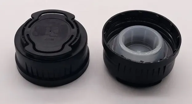
Figure-1 Image of plastic bottle cap used in the model
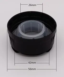
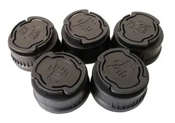
Figure 2 Dimensions of Plastic bottle cap used for practical applications. Figure 3 shows a lot of plastic bottle caps
PROCEDURE
The whole process is done sequentially and divided into a number of stages as follows:
- We approached with a geometrical checkup of the whole model and found numerous errors like needle faces, unnecessary triple cons and cracks in between some planes. After fixing the errors automatically or manually we revised the CAD model and distinguished it into smaller components for optimal Pre-processing.
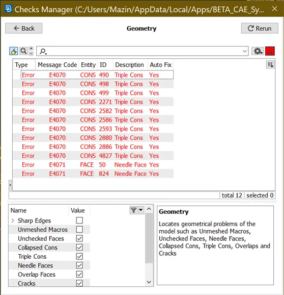
Figure-4 Geometric errors found in the CAD geometry
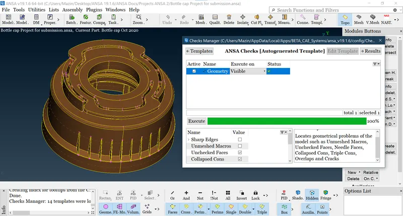
Figure-5 Geometrical defects all cleaned up for the whole model
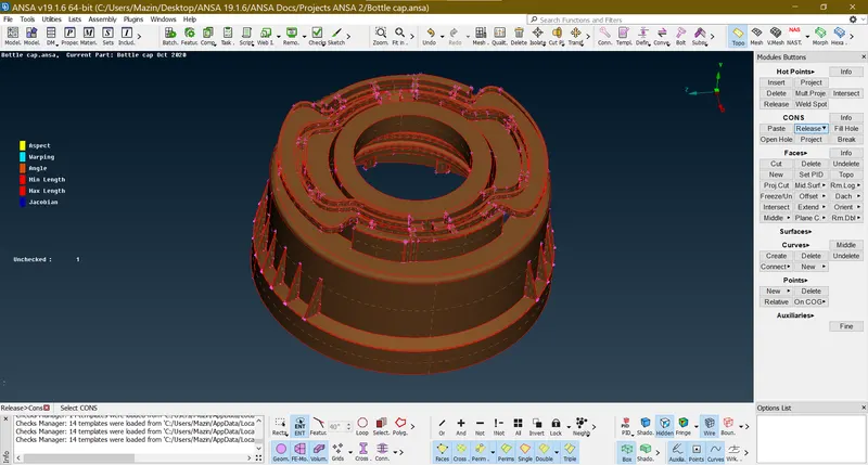
Figure-6 CAD model without topo clean up
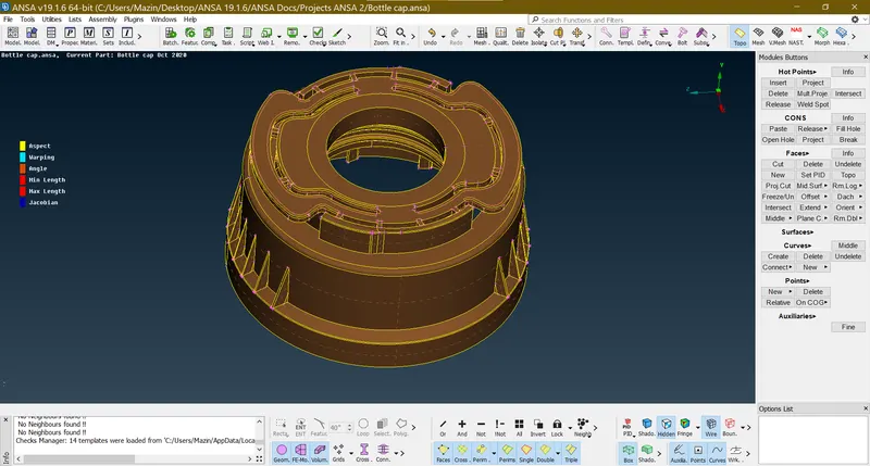
Figure-7 CAD model after Topo clean up
- Whilst arranging smaller entities of this bottle cap model for mid surface extraction we changed the thickness of the full CAD model for both perimeter as well as macros to 1 as displayed in the figures below. Because the difference between the original thickness and the allocated thickness is minimal when rounded off, the change in length has little effect on the distance between nodes.
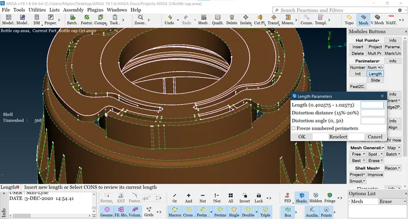
Figure-8 Parent geometry before changing the thickness
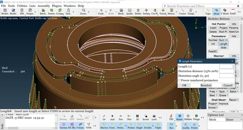
Figure-9 Parent geometry after changing the thickness
- Hence without further ado, we advance for mid surface extraction of all entities by various methods using the following commands viz.
- The offset button is used for entities whose thickness is uniform throughout and quicker results. TOPO module>FACES>OFFSET
- A middle button from the faces deck is used as an offset button to extract mid surface quickly. TOPO module>FACES>MIDDLE>SINGLE/MULTI
- We can also use a combo of Project from Cons deck, Middle from Curves deck and New from Faces deck of Topo module to obtain a mid-surface. Usually used for entities whose thickness and other dimensions are not uniform. TOPO MODULE>CONS>PROJECT TOPO MODULE>CURVES>MIDDLE TOPO MODULE>FACES>NEW>PLANNER/FITTED/COONS
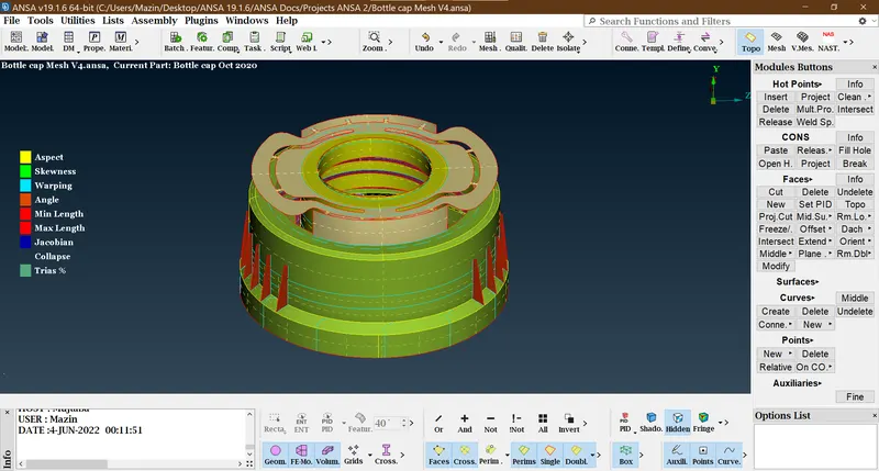
Figure-10 Mid surface extracted for full model
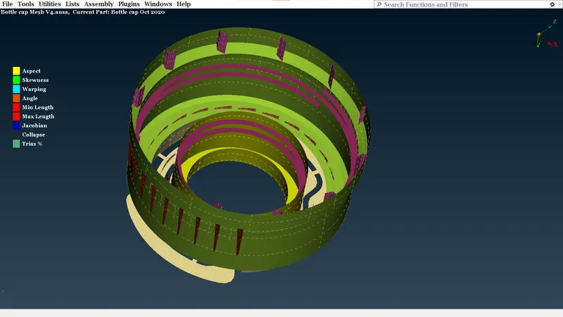
Figure-11 Isometric view for the mid surface of the full model
- We have many symmetrical entities where we use rotate command to replicate mid- surfaces like for middle teeth inside the cylindrical shell of a bottle cap model or bottom teeth on the inner periphery of the same shell. We use the transform button from Utilities Toolbar to perform this action.
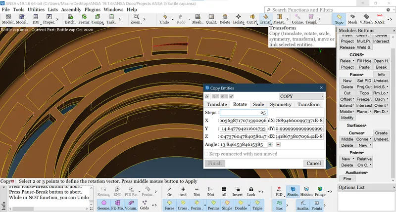
Figure-12 Transform used to extract mid surface for wedge-shaped teeth at the middle of the model
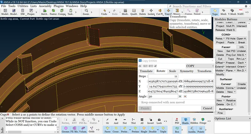
Figure-13 Transform used to extract mid surface for teeth at the bottom of the model
- After extraction of the mid surface from parent geometry is completed we advance towards the last part i.e. meshing. But before passing forward we enter the provided data in Quality Criteria and Mesh parameters. Furthermore, we set PIDs for all mid surfaces extracted from parent geometry and assign their respective thickness in order to attain a good and smooth mesh flow.
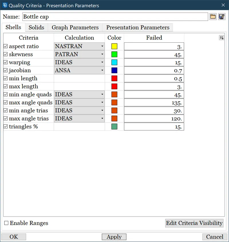
Figure-14 Quality criteria assigned for model
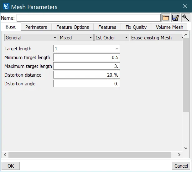
Figure-15 Mesh Parameters registered in the model
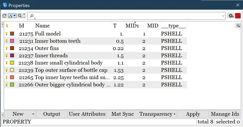
Figure-16 PIDs set for all entities of the model
- Eventually, we ended up meshing all PIDs formed lately within prescribed 5 thumb rules for tria’s by using various types of mesh. We use the best mesh or spot mesh in this model because of its intricate geometry as compared to the sheet metal model. Near few congested triple cons, 9 elements fail the requisite quality criteria that are to some extent quite acceptable. Presented below are different views of how to mesh flow for the whole model looks like after applying draw shell as solid in presentation parameters of quality criteria.
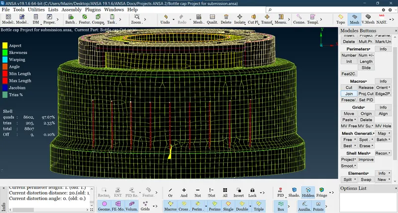
Figure-17 Complete mid surface extracted model surface meshed and drawn as solid with a specific thickness for each entity
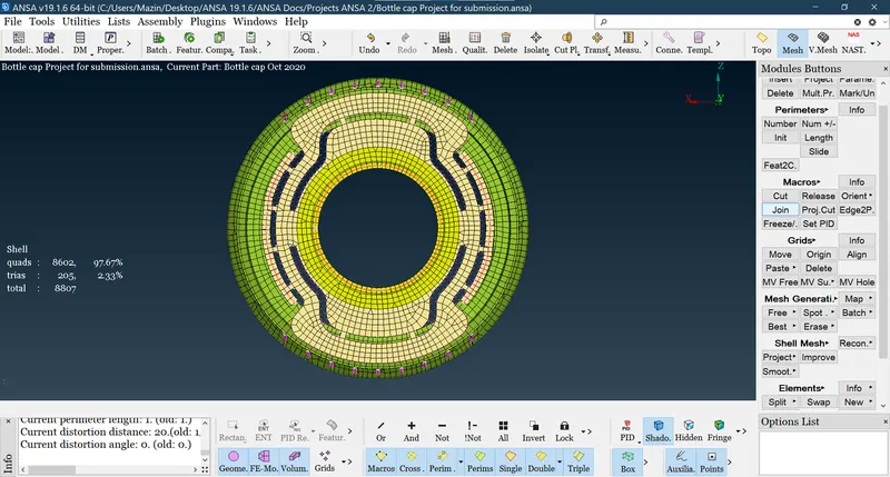
Figure-18 Top view of the complete 2D meshed model
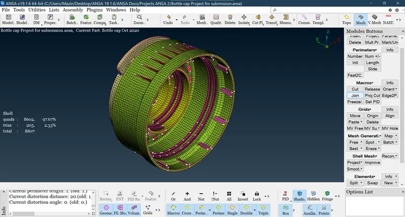
Figure-19 Isometric view of the complete 2D meshed model
LEARNING OUTCOMES
- It was a whole new level of experience to work on a component which has a blend of different surfaces with different dimensions or parameters.
- Using different methods of extracting mid surfaces with complex design parameters put us in good practice to attain a better optimization while using ANSA.
- At many points, new faces were generated with additional surfaces using a combo of New, Cut, Extend and Intersection that evaluated a better design for good mesh flow.
- To save time we used Transform>Rotate command for symmetrical entities to retrieve mid surfaces with uniform dimensions.
CONCLUSION
- Cleaned all geometrical defects in parent geometry like needless triple cons and needle faces.
- Changed length between nodes of perimeter and macros for parent geometry.
- Extracted mid surface for whole geometry and altered some gaps, voids and unnecessary surfaces with additional and needful faces and surfaces under specified limits.
- Set PIDs according to model configuration and design specifications. Input Quality criteria and mesh parameters and terminate the whole process with good meshing.
- Lastly, mark the "draw shell as solid" in the presentation parameters of quality criteria to get an overview of the thickness for a full meshed model.