Modelling Spotweld using Beam and Solid elements in LS-DYNA PrePost.
OBJECTIVE:
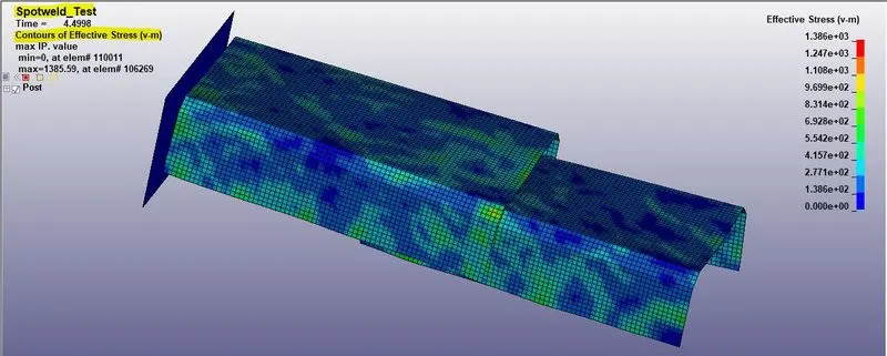
The objective of this simulation test is to compare the two weld methods Spotweld, Solid weld using the HEXA element in the provided model. The model is inputted with the LS-DYNA keywords. After checking the model, it is simulated and the results are analyzed.
PROCEDURE:
There are three steps to be followed to achieve the simulation of the drop test, they are
Model setup,
Output requests,
Results.
MODEL SETUP:
The model setup is nothing but, the input model(keyword file) is studied and inputted with the suitable parameters in the LS-DYNA PREPOST deck, they are as follows
Title,
Assigning material cards,
Section creation,
Creating Rigidwall,
Initial Velocity,
Spot weld creation,
1) Spotweld_Beam
2) Spotweld_solid
Contact interface,
Sectional_Force for nodes and elements,
Creating Control cards.
The model is opened through the command File--->open--->LS-DYNA Keyword file. or simply use the shortcut key ctrl+k. The unit system followed here is gm mm ms.
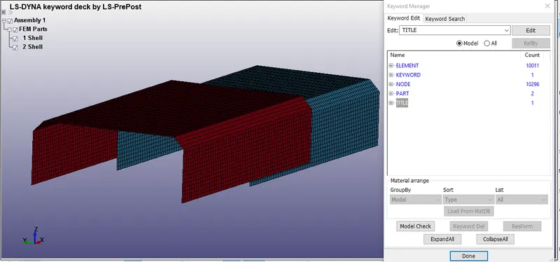
When the model is opened, it consists of only nodes and elements. The title of this test is saved as Spotweld_Test.
Assigning Section card:
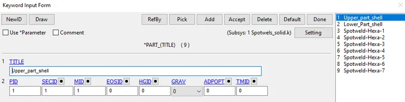
The material and the section for the shell are linked with the Shell parts through part creation. The command for the part is the Right-side toolbar--->model--->Keyword manager--->part command is used.
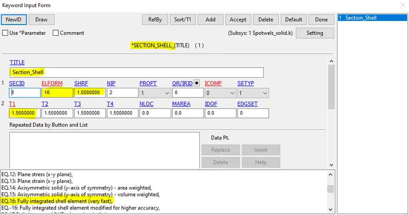
The element formulation card is represented as ELFORM=16 in this case. It means that the shell element formulation during the simulation is very fast. The section card is inserted through the command,
Right-side toolbar--->model & part--->Keyword manager--->section--->shell. The thickness of the shell component is assigned as 1.5mm. For both cases, the thickness of the shell part is fixed as 1.5mm.
Assigning Material card:
To assign the material to the parts separately, the command used is
Right-side toolbar>model>Keyword manager>Materials >001_Elastic card is used.
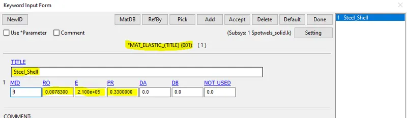
The material used for the Spotweld test is steel and the mechanical properties of the steel are listed below,
- Density= 0.00783 `(gm)/(mm^3)`
- Young's modulus=2.10 e+05 `(gm)/(mm*ms^2)`
- Poissons ratio=0.33
Finally, the Material card and the Section card for the shell parts are inserted through the command Model--->Keyword manager--->part--->insert Section/material card.
Rigid wall:
The next step is to create a Rigid wall in front of the crash box 10 mm away by using the *RIGIDWALL_PLANAR card.
This is done by selecting
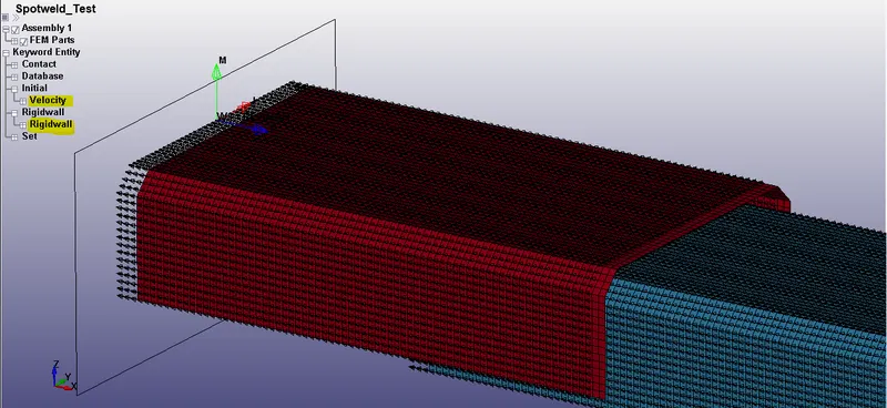
Create Entity--->RigidWall--->Create. The rigid wall type is selected as a Planar and defined vector with one point and a normal ie, 1n+NL here selected the one node, and the normal is created as a rigid wall. This rigid wall is translated/offset by 10mm from the crash box component.
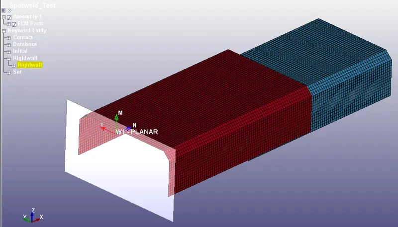
The white box in the window is a rigid wall and the normal is acting opposite to the global x-axis and it is denoted in blue color.
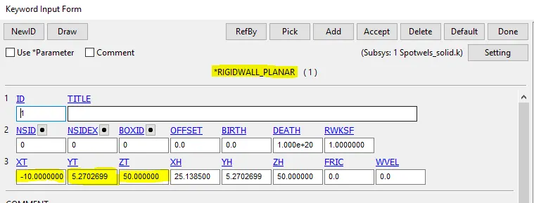
The rigid wall is placed correctly in the space where the x coordinates value is entered in a negative direction shows that the normal is acting in opposition to the crash box.
Initial Velocity:
The next step is to define a velocity of 50kmph (13.8889 mm/ms) and assigned it to each node of the selected crash box component, under
Right-side toolbar--->model--->Keyword manager--->Initial--->velocity command is used. The Crash box is selected by pick option with respect to part as shown below.
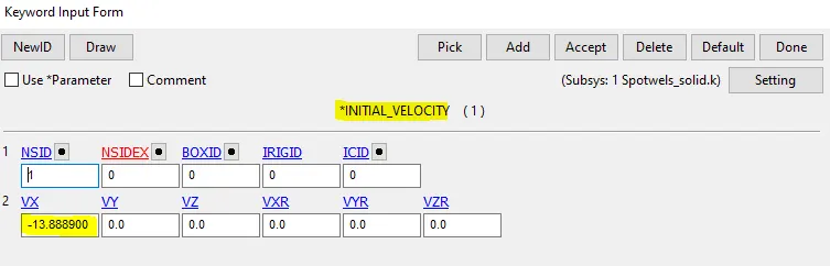
The initial velocity for the assembly is inserted in the x-axis tab in a negative direction shows that it is acting opposite to the global x-axis.
Spotweld:
The spot weld(resistive welding) is a type of electric resistive welding used to weld various sheet metal products, through a process in which contacting metal surface points are joined by the heat obtained from resistance to electric current.
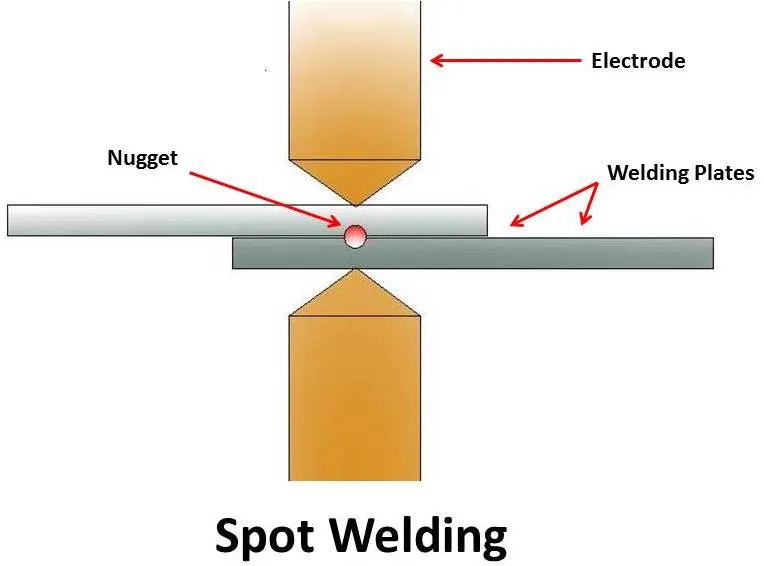
The process uses two shaped copper alloy electrodes to concentrate welding current into a small "spot" and to simultaneously clamp the sheets together. Workpieces are held together under pressure exerted by electrodes. Typically the sheets are in the 0.5 to 3 mm (0.020 to 0.118 in) thickness range. Forcing a large current through the spot will melt the metal and form the weld.
The attractive feature of spot welding is that much energy can be delivered to the spot in a very short time (approximately 10–100 milliseconds). That permits the welding to occur without excessive heating of the remainder of the sheet.
Creating spotweld:
The spot-weld can be modeled as beam and solid elements by using the following techniques,
- To represent as a beam element, we use *CONTROL_TIED_SHELL_EDGE_TO_SURFACE card.
- To represent a solid element, we use the *CONTROL_SPOTWELD card.
Spot-weld modeling using Beam element:
The spot weld modeled using beam element is created through the command,
Element & Mesh--->Ele generation--->beam--->two node sets--->create.
Now this beam element act as a spot weld.
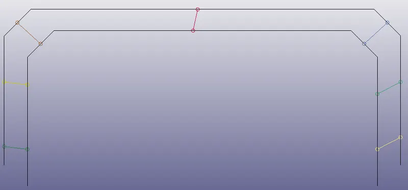
The LS-DYNA automatically creates a Section card (*SECTION_BEAM) and the Material card (*MAT_CABLE_DISCRETE_BEAM), and we need to delete these cards and assign our required material and section cards.
Defining the Material card for Beam Element
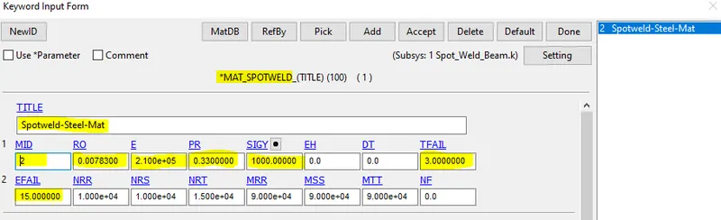
For the beam element, the material card is assigned as the *MAT_100 that is especially for the spot weld material. The values are assigned and here we are taking a time-dependent failure concept rather than the force-dependent failure concepts like Effective plastic strain, maximum axial stress, maximum shear stress, Force resultant. So to keep this problem as a Time-dependent failure we given other failure terms as a higher value.
Defining the Section card for Beam Element
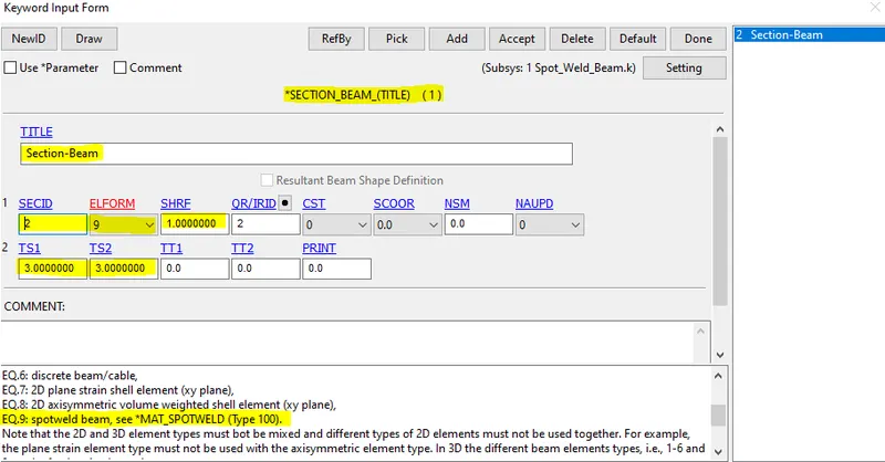
For the beam element, the section property is assigned by using the *SECTION_BEAM card. It is important to assign element formulation (ELFORM) as 9 because the *MAT_100 spot weld material model only applies for ELFORM 9 formulation in the case of the beam element. The cross-section type is selected as tubular since the default cross-section(rectangular) gives zero cross-section area during the simulation and the beam thickness at both ends is given as 3mm.
Defining the Contact card for Beam Element
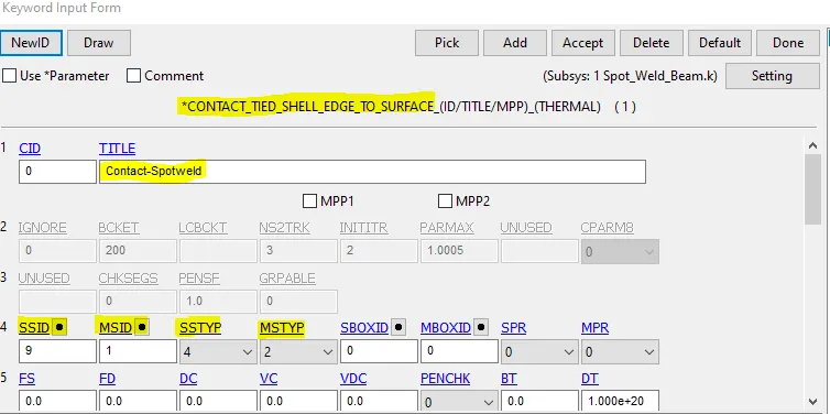
The contact for the beam element is *CONTACT_TIED_SHELL_EDGE_TO_SURFACE card.
Here the master set id will be Part id and the Slave set id will be nodes of beam weld element.
For defining the Slave set select beam nodes so as to create the set and the steps are mentioned below,
Entity Create--->SetData--->*SET_NODE--->Pick the nodes--->Apply.
For defining the Master set select both the metal sheet parts and the steps are mentioned below,
Entity Create--->SetData--->*SET_PART--->Pick the part--->Apply.The command used to create a contact interface for the beam element is
Model & part--->Keyword manager--->contact--->Tied_Shell_Edge_to_Surface. is selected.
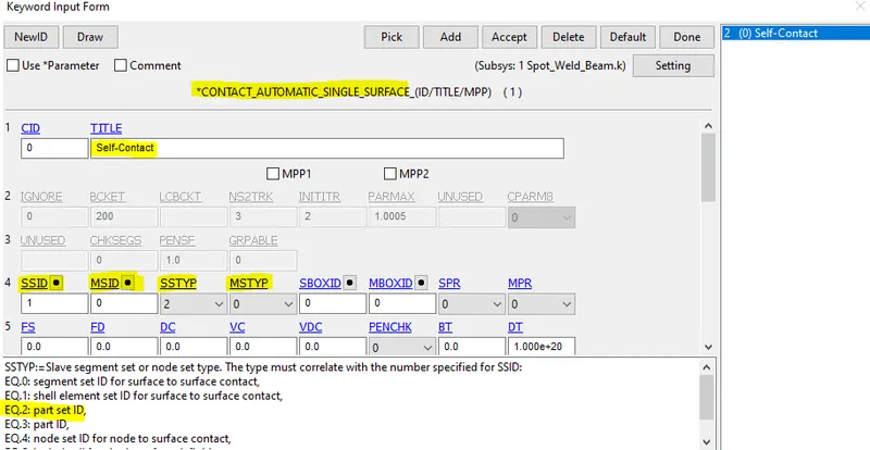
we need to create an Automatic_single_surface contact card for the shell parts to ensure that after the spot weld breaks the parts come to each other they shouldn't penetrate. Here the parts-sets are the slaves
Modeling Spotweld with HEXA elements:
The spot weld modeled using solid element is created by using the command,
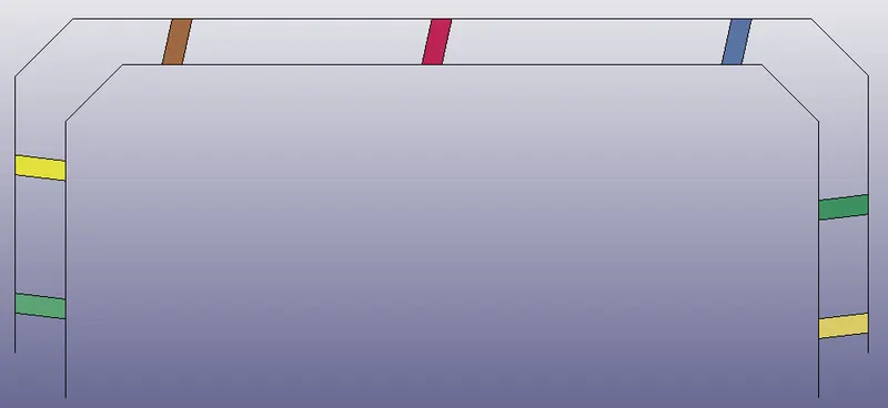
Element Tools--->Element Editing--->Create--->Hexa and select the elements from top and bottom parts respectively. Now this solid element act as a spot weld.
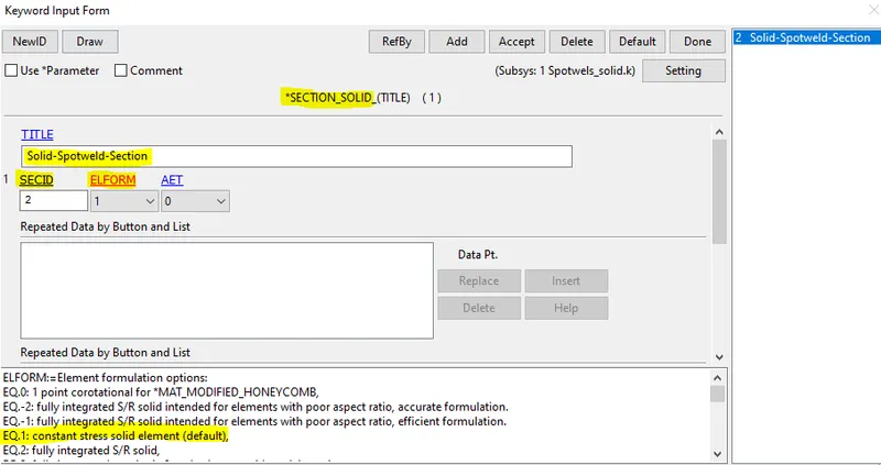
Defining the Section card for Solid Element
For the solid element, the section property is assigned by using the *SECTION_SOLID card. It is important to assign element formulation (ELFORM) as 1 because the *MAT_100 spot weld material model only applies for ELFORM 1 formulation in the case of the solid element.
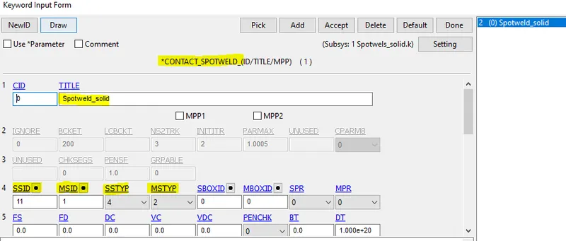
Defining the Contact card for Solid Element
Here for the solid element, the contact type to be used is the *CONTACT_SPOTWELD card.
Here the master set id will be Part id and the Slave set id will be nodes of solid weld element.
For defining the Slave set select solid nodes so as to create the set and the steps are mentioned below,
Entity Create--->SetData--->*SET_NODE--->Pick the nodes>Apply.
For defining the Master set select both the metal sheet parts and the steps is mentioned below,
Entity Create--->SetData--->*SET_PART--->Pick the nodes>Apply. The command used to create a contact interface for the beam element is
Model & part--->Keyword manager--->contact--->Spotweld. is selected.
Defining the Material card for Solid Element
The same material card is assigned for this spotweld material too. *MAT_100. Here also the time-dependent failure is inputted.
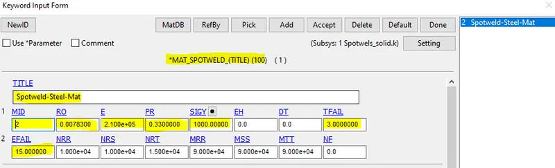
The TFAIL for the spotweld elements are at 3ms and the Effective plastic strain failure(EFAIL) value also inputted into the system.
Creating Cross_Sectional Force:
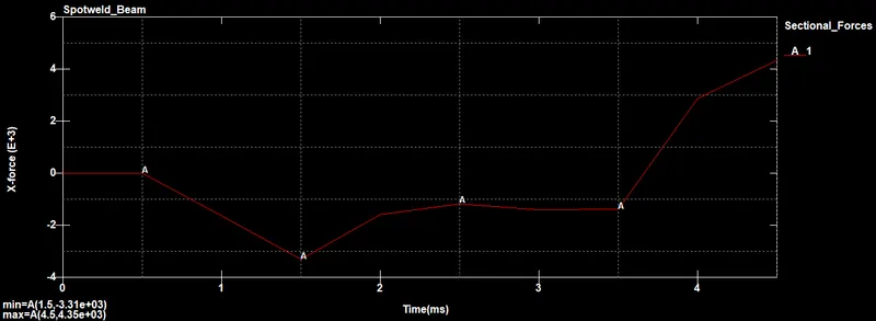
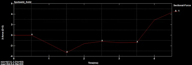
In the question, the sectional force for the nodes and elements in the shell parts along its length is to be recorded and plotted in LS-DYNA. To do that the command used here is
Model--->keyword manager--->database--->Cross_section_Set. command is used. The node set and the shell set is created using the command Model--->create entity--->set_data--->set_node/elem. is used.
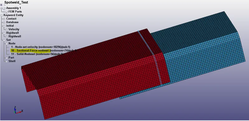
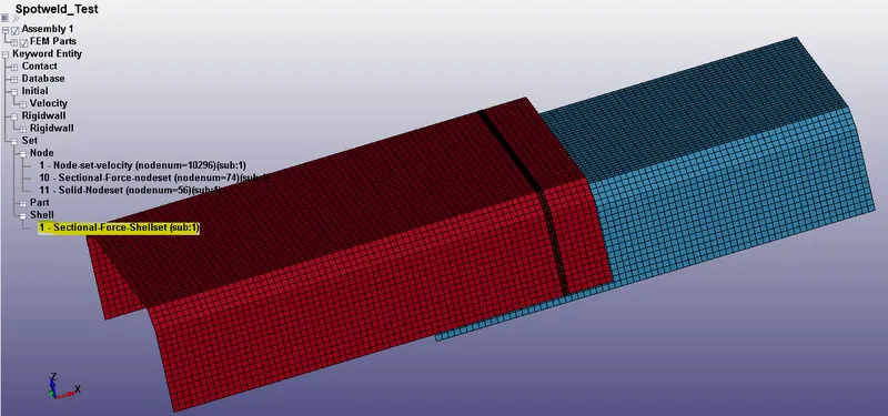
The cross-section set is created in the upper shell part of the model and the section is near to the weld elements. For both cases, the sectional forces input is the same.
Control cards:
The control cards are used to get the output plots and simulation from the
Model--->keyword manager--->database--->ASCII/binary d3plot are used. The list of control cards for the output are listed below,
DATABASE_BINARY_D3PLOT --> Used to find out the animation of the process,
DATABASE_ASCII_NODOUT --> To find the Nodal motions,
DATABASE_ASCII_ELOUT---> To find Element Output Data,
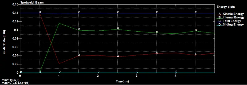
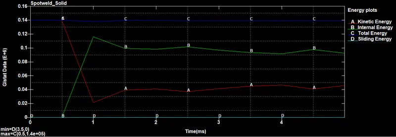
DATABASE_ASCII_GLSTAT --> To find the global statistics and energies,
DATABASE_ASCII_MATSUM --> To find the material energies,
DATABASE_ASCII_SLEOUT --> To find the Contact interface energies,
DATABASE_ASCII_SECFORC --> To find the Cross-section forces data.
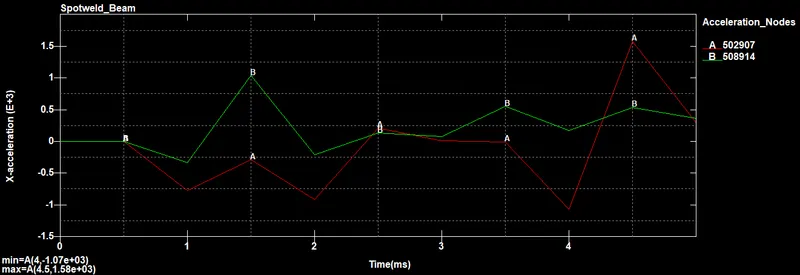
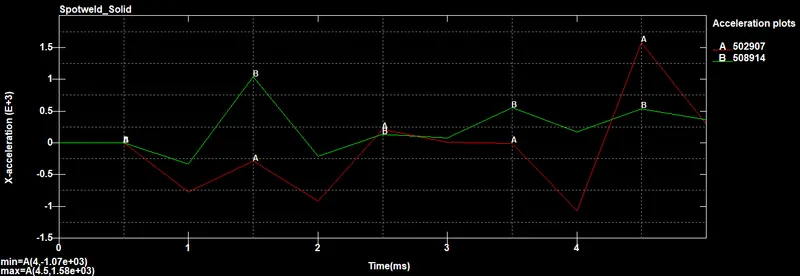
The acceleration plot of a node and element of the model can be done by picking the desired node and element by using *DATABASE_HISTORY_NODE and *DATABASE_HISTORY_SHELL card.
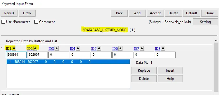
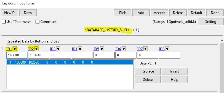
The termination time of the simulation is set to 5ms. It is set from the command
Model--->keyword manager--->control--->termination.
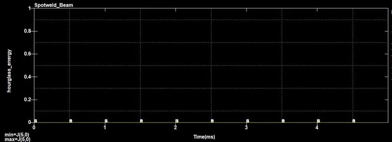
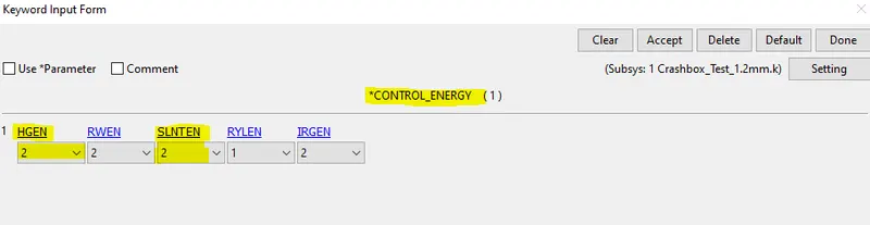
The Hourglass and the Sliding energy both are recorded and plotted using the command
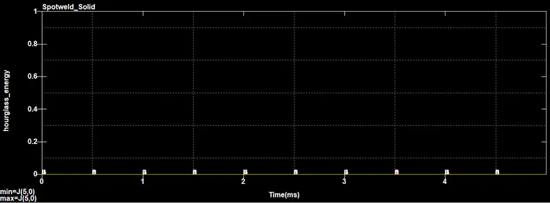
Model--->keyword manager--->control--->energy. The HG energy is inputted only for Spotweld Beam elements and in solid spot elements,the full integration takes place and no need for the HG and sliding force formulation cards.
MODEL CHECK:
The model checking is the last quality check and it is mandatory for all the methods. It highlights the errors and the warnings that present in the model.
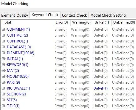
The errors are taken into concerns and not the warnings, unreffered assembllies are taken into account.
Output requests:
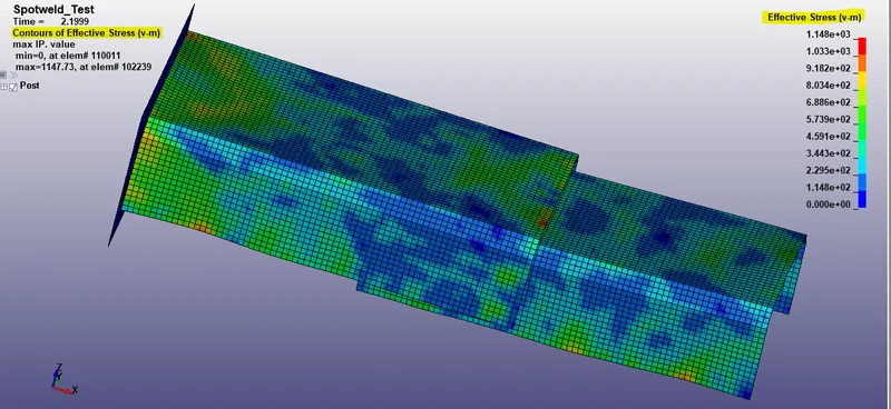
For the output request following files are loaded and displayed below through LS-DYNA.