Assignment 3
OBJECTIVE:
The main objective of this assignment is to compare the simulation result with the default input values(/Def_Shell) and the simulation with the element properties changed.
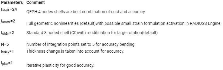
Then the plot like Hourglass energy, kinetic and Internal energy, Rigidwall Forces are compared. From that comparision we have to conclude the difference in Hourglass energy.
1.RUNNING THE SIMULATION FOR THE CRASH BEAM:
In this we have two conditions to achieve, that is;
Simulation with no change in element properties,
Simulation with changes in element properties.
Importing the input file:
The input file is imported from the local file directory by the import option in the Hyperworks tab.
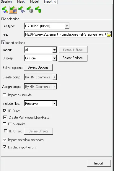
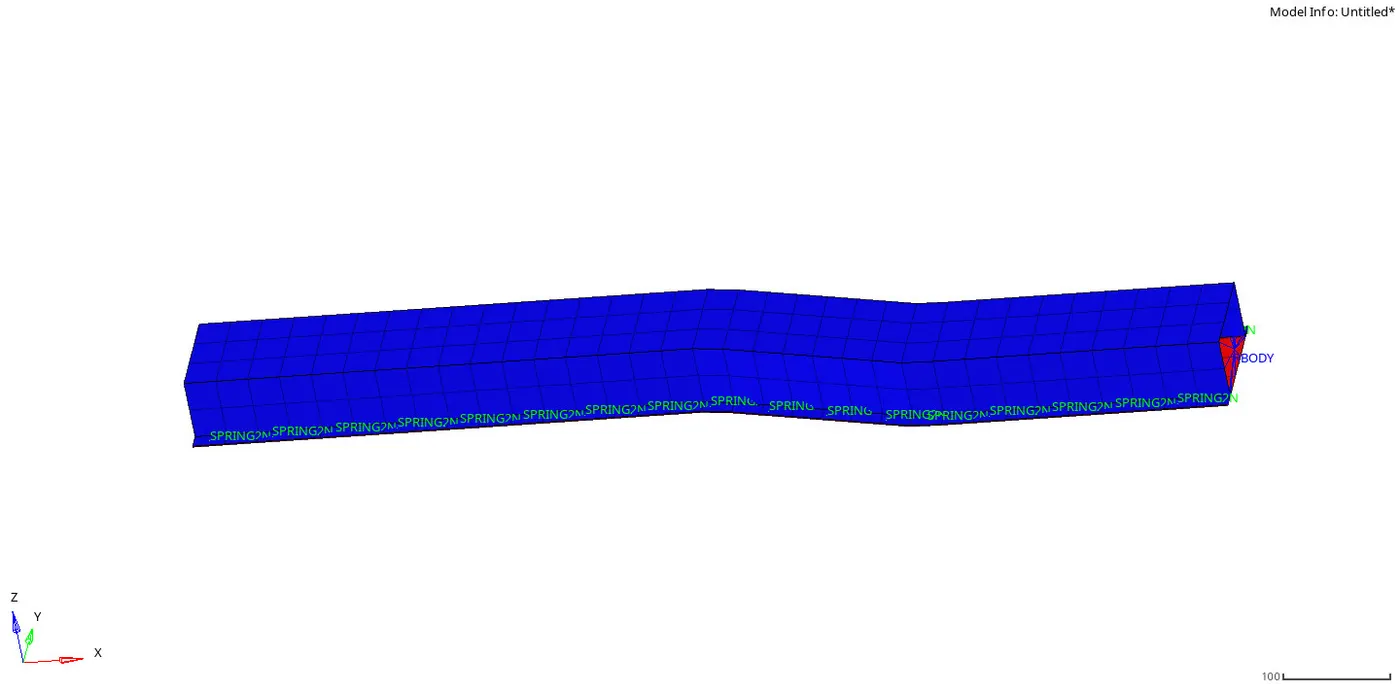
Then the run time is set to 55ms.
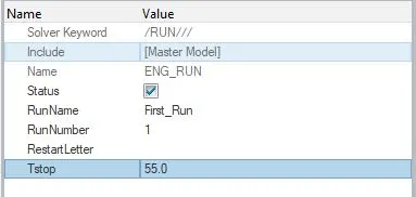
The number of animation steps during simulation is to take in between minimum of 25 and maximum of 60. So i take the mid value of 45. so the calculation is like;
Animation o/p time = Total run time/no.of steps
=55/45
Animation o/p time = 1.2222.
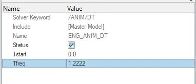
For the first condition the element properties are set to default values(/Def_shell) and the plot like Rigid wall force, Kinetic energy, contact energy and the Hourglass energy are plotted.
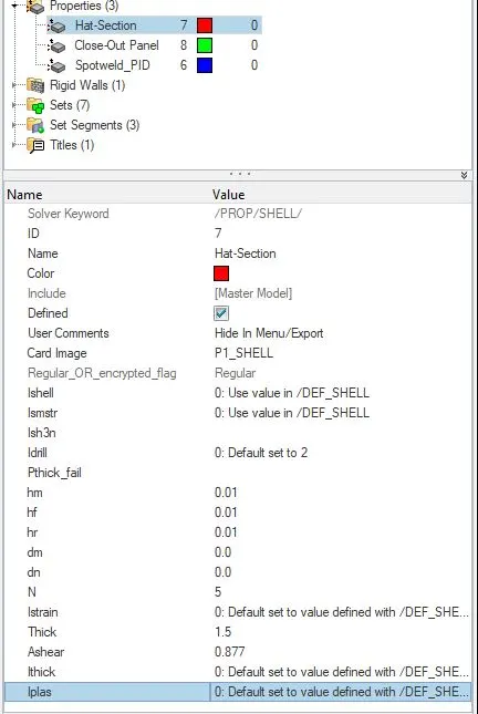
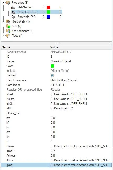
After this step the simulation is initiated by going to the command prompt Analysis--->RADIOSS--->Save the directory file.
 The output file is stored in the local directory and the _0001.rad file is opened to check the Energy error and the Mass error.
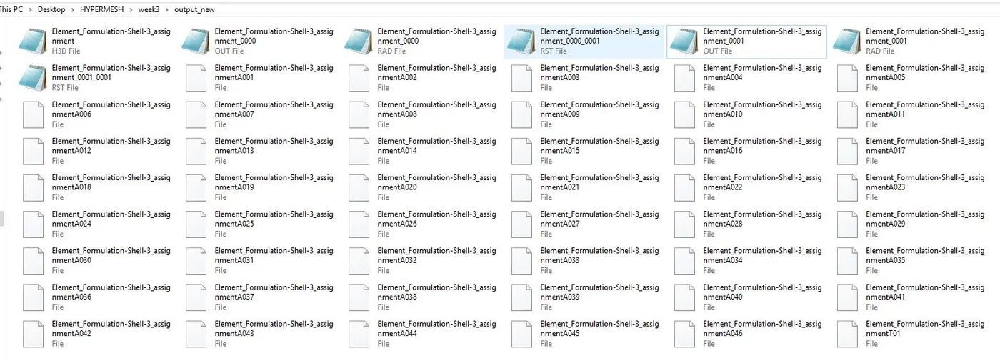
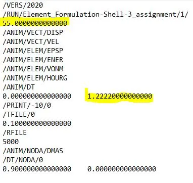
The frequency for the simulation we taken is about 45 and the solver creates 46 files and it is created properly.
ENERGY ERROR:
The error that occur due to hourglass effect in the element. Due to hourglass effect without absorbing no energy from the deformation the energy value is always in negative value.
This value shouldnot exceeds +15% and less than this at the end of the computation. For good results +5% is acceptable values.
For most accurate results to be expected the values should be between -5% to -15% .
In QEPH shell element formulation the energy can be slightly positive in nature because there is no Hourglass energy is formed and acuuracy is more.
KINETIC ENERGY:
The energy created by the movement of the beam by giving some external force. It is the energy of mass in motion. The kinetic energy of an object is the energy it has because of its motion. Always that energy is a scalar quantity, that it does not depend on direction, and it is always positive.
They are transverse and rotaional in nature. Both are recorded in the output file. In this problem only transverse motion presents.
INTERNAL ENERGY:
It is also known as potential energy. Potential energy is a type of energy an object has because of its position. It is the energy that is stored in an object due to its position relative to some zero position.
CONTACT ENERGY:
When a deformation is done in between the nodes by the external force applying, the energy created by the contact is called sa contact energy.
It may be both in positive and negative values.
HOURGLASS :
Hourglassing is an instability that happens in reduced integrated elements.
The reduced integration has two benefits;
Faster computation,
Can give better bending results (less stiffness).
But it can also produce a shearing mode that has no strain energy associated with it and as a result the elements can form an hourglass shape with no strain energy.
HOURGLASS ENERGY:
Hourglass ( HG ) modes are nonphysical, zero-energy modes of deformation that produce zero strain and no stress. It occurs only in under-intetgrated (single integration point) solid, shell, and thick shell elements.
This is easily removed by either selective reduced integration where the shear mode is fully integrated or by the addition of hourglass energy stabilization(by adding an extra external force to the elements subjected to the hourglass effect).
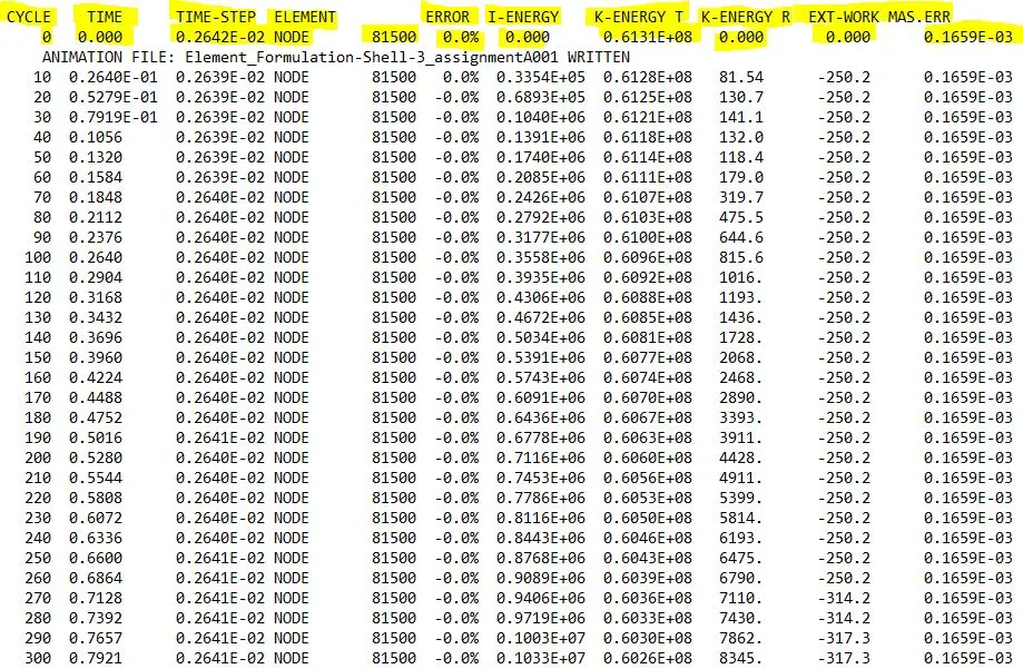
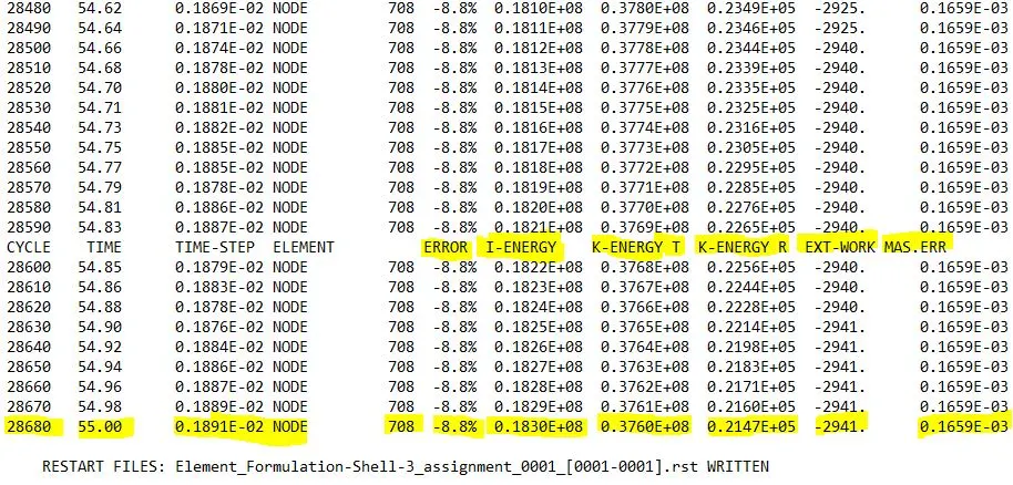
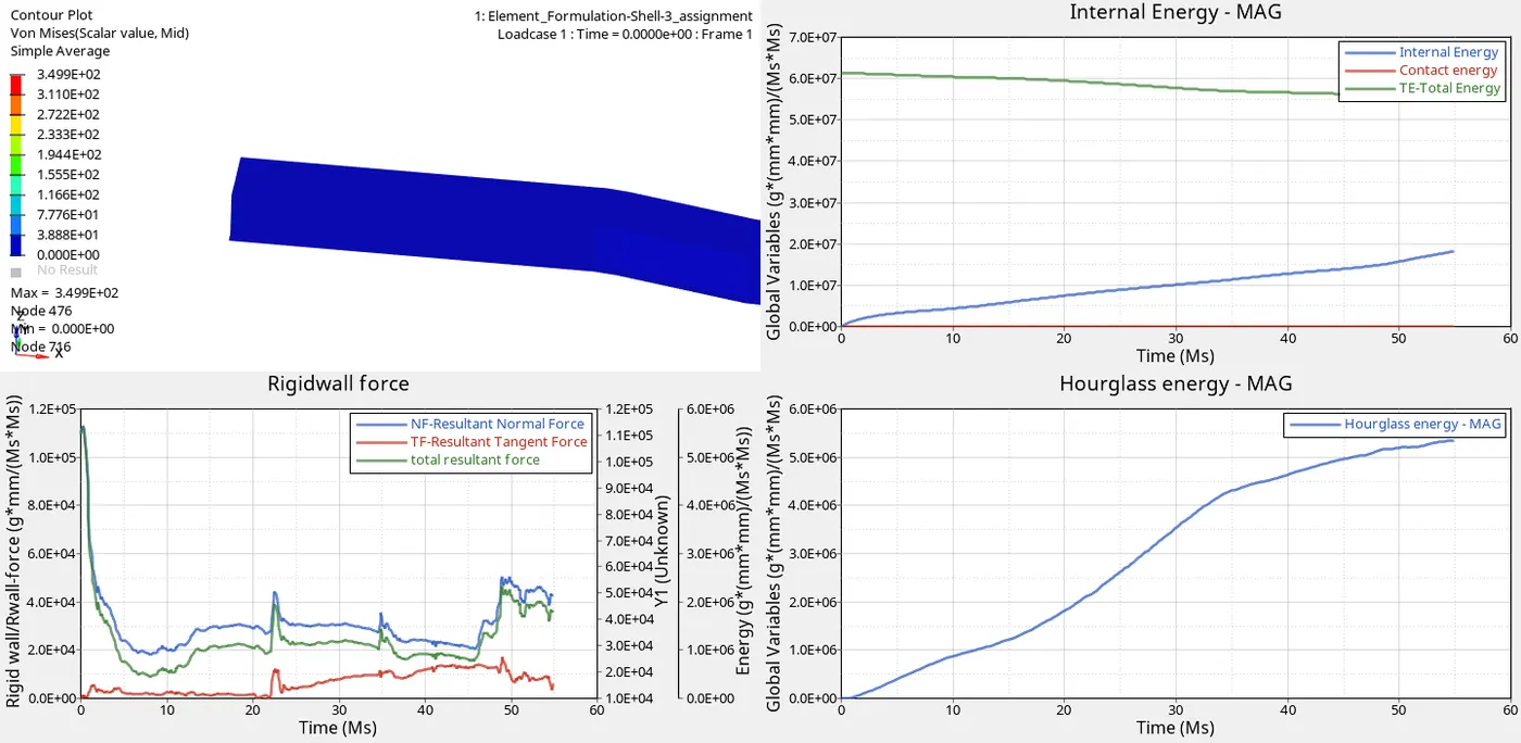
The energy error in the start is about +0% and at the end of the simulation it is about -8.8%.
The Kinetic energy with transvertional movement onlt recorded by the solver because the movement is transverse in nature not rotational in nature.
The total time of 55ms was ran for the cycle of 28680 are recorded.
PLOTTING THE RESULTS:
From the above computations energy plots like hourglass energy, contact energy, internal energy, total energy are plotted.
And forces like Rigidwall forces/Rwall force are also plotted.
To plot this graphs open Hyperview--->open .h3d file from the local directory saved.

After importing the results of the simulation the .h3d file runs the simulation for deformation effects in the crash beam.
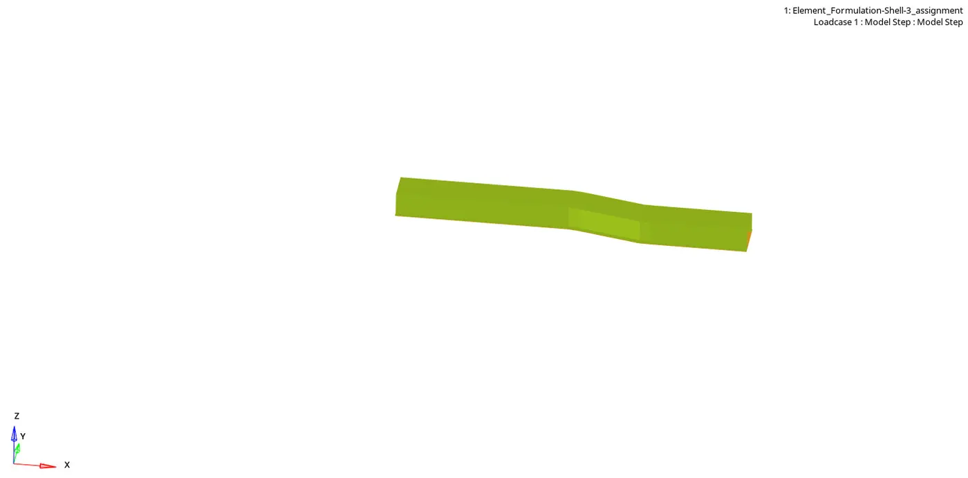
After hiding the fixed siuface the weld spots are vizulaised larger and it is not affected from the deformation.
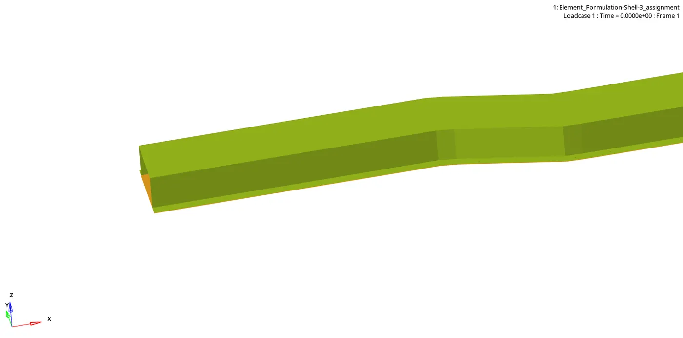
From the input file the one end is fixed and the other end is only subjected to some external push.
From this the graphs are plotted by opening the Hyperview 2D---> open T01 file(time history file).

From this tab the global variables is selected ang variables like hourglass energy, internal energy, contact energy are selected.
The Rwall forces are also selected. In that tab resltant force, tangent force(frictional force), normal force are also selected.
CONTOUR TAB:
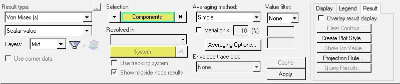
The contour tab is used to differentiate the deformation effect in different areas of the element during the external push applied.
In that tab the von mises stress is plotted and the maximum value of 3.499E+02 in the node 476 is reached.
VON MISES STRESS:
Von Mises stress is a value used to determine if a given material will yield or fracture. The von Mises yield criterion states that if the von Mises stress of a material under load is equal or greater than the yield limit of the same material under simple tension then the material will yield.
The theory states that a ductile material starts to yield at a location when the von Mises stress becomes equal to the stress limit. In most cases, the yield strength is used as the stress limit.
FINAL RESULT:
CONDITION 2:
In condition 2 we have change the element properties and run the simulation like the first condition.
The run time 55ms and the animation steps with the frequency of 45 is set as default values.
The crash beam that we take is same as in the second condition and that is imported from the same file directory.
The only change is to change the element properties in the properties list in the model view.
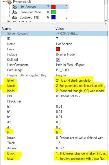
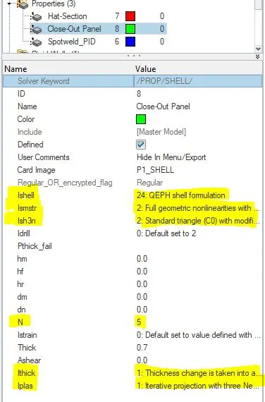
After changing the values the simulation gets initiated and the new output file(_0000.rad) saved in the new file directory.

After the import is complete the RADIOSS engine starts the simulation and saved it in the directory file.
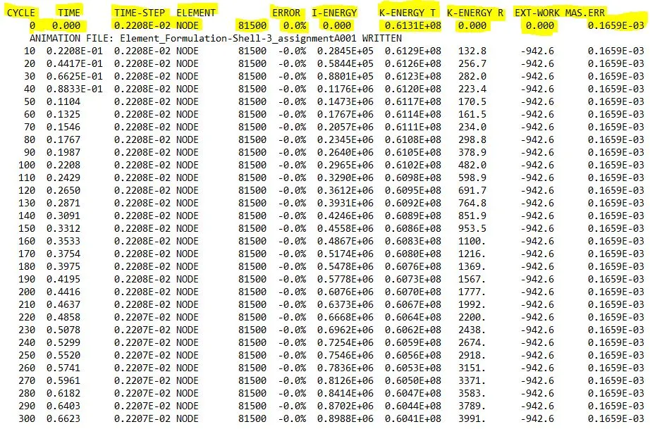
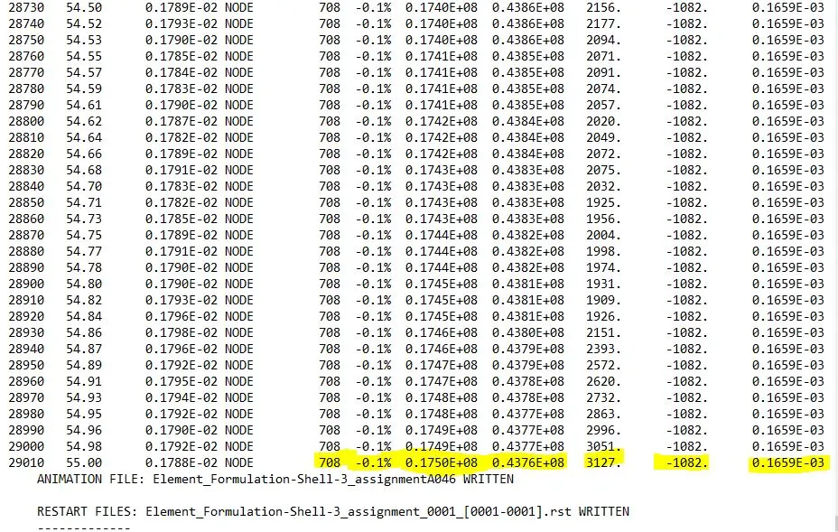
By using the QEPH shell formulation and other changes in the element properties list makes the energy error to come up with accurate values. This means the Hourglass effect and the Hourglass energy is approximately zero in this condition.
By the start of the simulation the energy error is about -0% and at the end it is about -0.1%.
This means the energy absorbtion of the element due to hourglass is almost nil in this simulation condition.
PLOTTING THE RESULTS:
From the above computations energy plots like hourglass energy, contact energy, internal energy, total energy are plotted.
And forces like Rigidwall forces/Rwall force are also plotted.
To plot this graphs open Hyperview--->open .h3d file from the local directory saved.

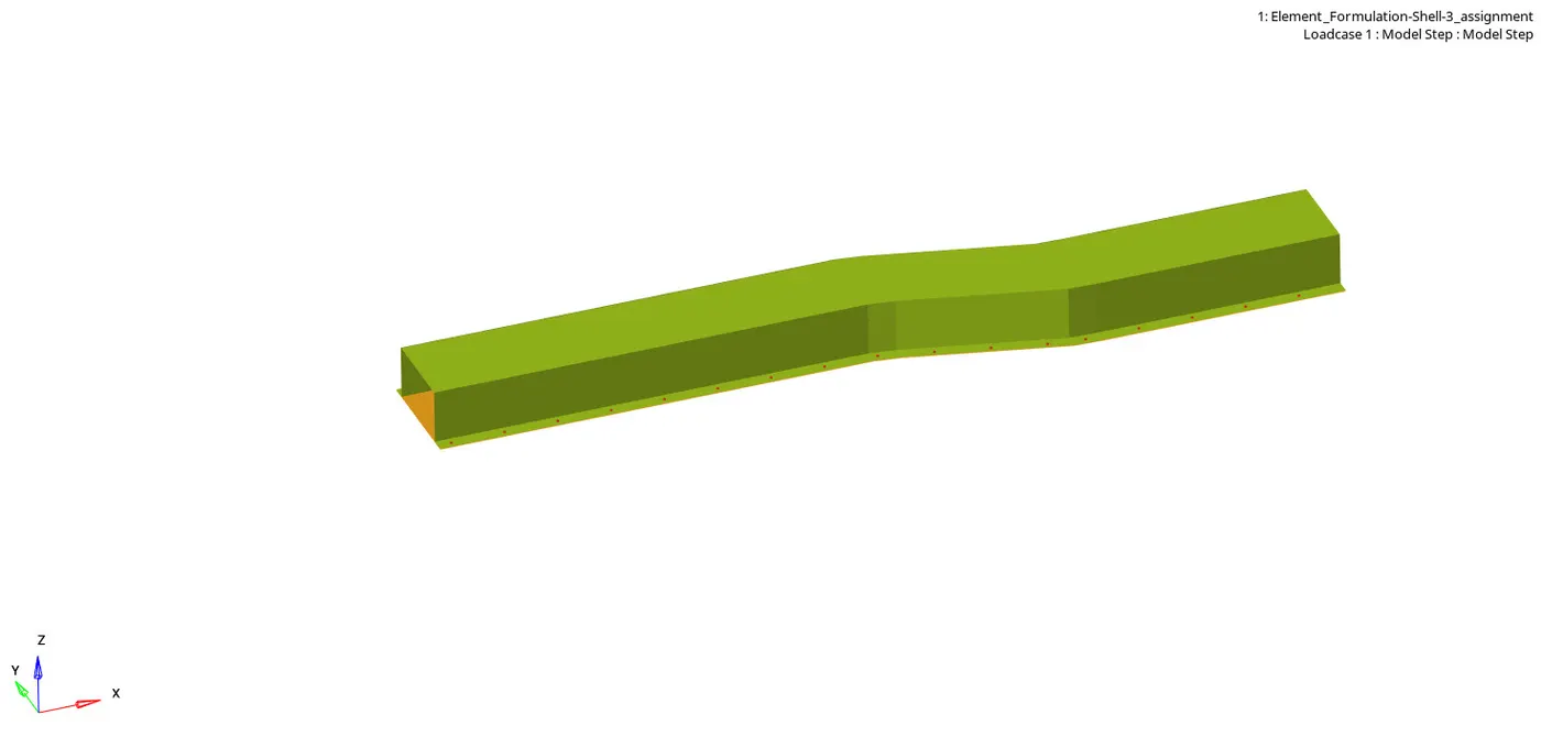
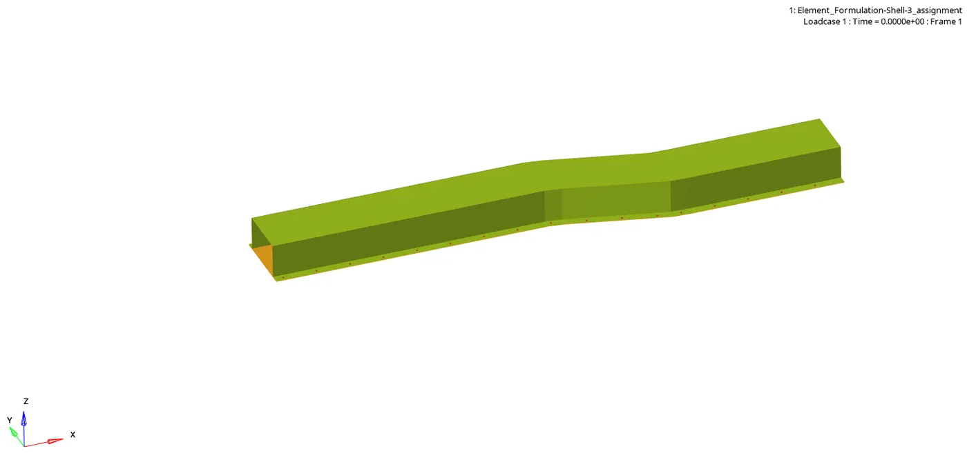
From the input file the one end is fixed and the other end is only subjected to some external push.
From this the graphs are plotted by opening the Hyperview 2D---> open T01 file(time history file).

From this tab the global variables is selected ang variables like hourglass energy, internal energy, contact energy are selected.
The Rwall forces are also selected. In that tab resltant force, tangent force(frictional force), normal force are also selected.
CONTOUR TAB:
The contour tab is used to differentiate the deformation effect in different areas of the element during the external push applied.
In that tab the von mises stress is plotted and the maximum value of 3.499E+02 in the node 707 is reached.
FINAL RESULT:
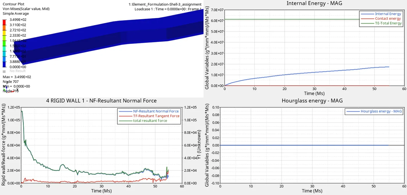
Due to the element properties change the hourglass energy is almost zero in this case. the peak value of the hourglass effect is about -0.1%.
Both Normal force and the total resultant force is in same parallel line because of the uniform deformation is done all over the system.
In both the case the frictional force is almost same because it is a resistance force relative to the moving of the object.
CONCLUSION:
From condition 1 and 2 we have to conclude that when the hourglass effect is formed due to the less stiffness to the system.
By assigning the QEPH shell formulation the energy error is reduced to -8.8% to -0%
The element properties are changed for the below purposes, they are;
Ishell= 24 (QEPH): Formulation with hourglass physical stabilization for general use.
Ismstr - Small strain formulation=2: Small strain formulation is activated from time t = 0. It may be used for a faster preliminary analysis.
Ish3n =2: 3-node shell formulation flag. This property is used for standard triangle with large modification in rotation.
Ithick = 1,It is used to shell resultant stress calculation. The small strain option is automatically deactivated in the corresponding type of element.
Iplas =1,It is used to shell resultant stress plasticity calculation. The small strain option is automatically deactivated in the corresponding type of element.
The change in Mass error is not so different in both the cases because it is independent of the element properties changes.
The von mises stress in both the case are same but in both condition it acts in different nodes. The max stress is about 3.499E+02 and for case 1 it acts on node 476 and for case 2 it acts on node 707.
LINK TO OPEN THE STARTER FILE AND ENGINE FILE:
https://drive.google.com/drive/folders/1wZINul5HYOC9QDAEC7Iusx-axLLB6d7C?usp=sharing