Child Pedestrian Head Impact Test on a Car Hood and calculated the HIC value using LS Dyna.
OBJECTIVE:
In this challenge, a children's head foam model is provided and supposed to replicate a scenario where this head foam will impact a car bonnet. The hood model is an elasto-plastic material card that has to be used. From the simulation, the head impact coefficient must be calculated manually and with the help of LS-PrePost. There are three cases that are simulated and compared to each other.
Case1: Simple head model and rigid wall.
Case2: Child head-foam and rigid wall.
Case3: Child head-foam and Hood.
INTRODUCTION:
Child Head Impact:
The car-pedestrian accidents account for a considerable number of automobile accidents in industrialized countries. Head injury continues to be more concerned with Automobile impacts. Because the head is the most seriously injured part in many collisions including in pedestrian automobile collisions. To reduce the severity of such injuries International safety committee has proposed subsystem tests in which head foam impactors are impacted upon the car hood.
Currently in India, Automotive Indian Standard (AIS) 100, Amendment 1 is used to evaluate the performance of vehicles against pedestrian safety. This standard has been harmonized from the International evaluation standard Global Technical Regulation No. 9 (GTR 9), whose purpose is to bring about an improvement in the construction of the fronts of vehicles and, in particular, those areas which have been most frequently identified as causing injury when in collision with a pedestrian or other vulnerable road user. The tests required are focused on those elements of the child and adult body most frequently identified as sustaining an injury, (i.e. the adult head and leg and the child's head). To achieve the required improvements in the construction of vehicles, the tests are designed in such a way that they will represent the Real-world accident scenario.
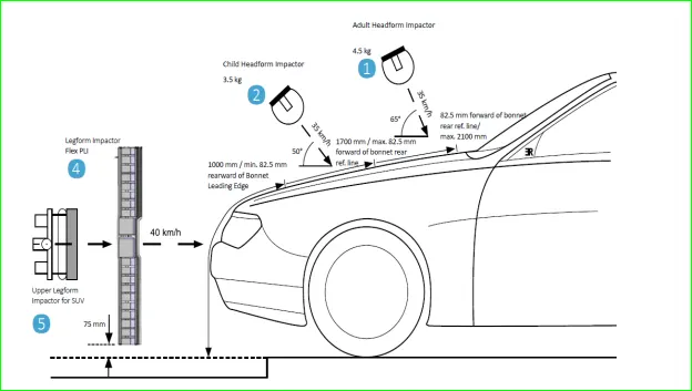
The different impactors used in predicting the performance against pedestrian safety are the lower leg foam and upper leg foam impactors (representative of the adult leg) and the adult and child head foam impactors (representative of the adult head and child's head). Head injury is a more life-threatening and most common cause of pedestrian deaths in pedestrian vehicle collisions. It was decided to focus on these impactors and test procedures as a part of this study.
Wrap Around Distance (WAD):
When a car crashes on the pedestrian, the whole human body wraps around the front shape of the car, and the head impacts on the bonnet or the windscreen. The distance at which the head impacts on the car from the ground is mentioned as Wrap Around Distance (WAD).
To be specific the Wrap Around Distance is a measurement of the distance from the ground to the head impact zone over the outer surface of the car. The wrap-around distance is measured longitudinally in the center of the vehicle from the ground.
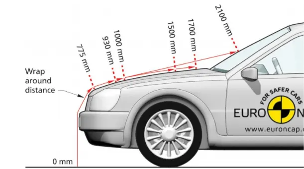
The severity of the injury caused by the frontal crash depends on the type and shape of the vehicle, the speed of the vehicle, and the movement of the pedestrian relative to the vehicle. In addition to these parameters, the wrap-around distance plays a major role in the safety measures of a pedestrian.
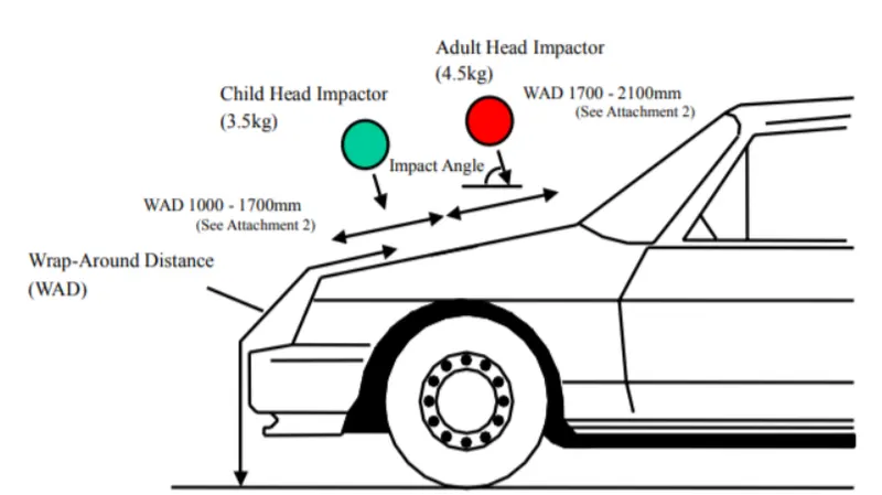
During the crash analysis, based on the Wrap Around Distance(WAD), two test areas will be created namely the Child head impact zone and the Adult head impact zone. The child head impact zone is between 1000 to 1700 mm WAD and the adult head impact zone ranges between 1700 to 2100 mm WAD respectively.
Head injury criteria (HIC)
The head foam impactors are used to test the behavior on vehicle structures such as the hood. In a pedestrian-vehicle impact, the kinematics and severity of pedestrian injuries are affected by the impact locations on the vehicle and body velocities after impact. The objective of this project is to analyze the pedestrian kinematics in a Pedestrian-Car accident scenario and determine the Head Injury Criteria (HIC) from the head resultant acceleration, for head impacts on the vehicle hood.
The equation used for the measurements of the head injury of the whole model for the pedestrian head impact was Head Injury Criteria (HIC). It has been used to predict the risk of engine hood to a pedestrian during the collision.
HIC is calculated according to the below Equation

Where
a: the Resultant Acceleration (as a multiple of 10 ms-2 or about 1 g
t1, t2: two-time instants (in seconds), which define the start and end of the recording when HIC is at maximum. Values of HIC at the time interval t1-t2.
For example, At HIC=650,
90% probability of level 1,
55% of level 2,
20% of level 3,
5% of level 4.
Abbreviated Injury Scale (AIS):
Level 1: Slight damage to the brain with headache, dizziness, no loss of consciousness, confusion.
Level 2: Concussion with or without skull fracture, less than 15 minutes of unconsciousness, detached retina, face, and nose fracture.
Level 3: Concussion with or without skull fracture for more than 15 minutes of unconsciousness without severe neurological damage, multiple skull fractures, loss of vision, multiple facial fractures, cervical fracture without damage to the spine.
Level 4: Multiple skull fractures with severe neurological damage.
For the whole simulation, the unit system followed is kg/mm/ms.
CASE-1; Simple head model and rigid wall:
Opening the model:
The model is opened through the command File--->open--->LS-DYNA Keyword or by pressing the shortcut key ctrl+k.
Creation of Rigid wall:
The planar rigid wall is created normal to the Z-axis and placed 20 mm away from the simple head foam geometry.
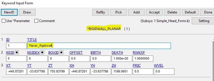
The command used for the Rigidwall creation is Model--->keyword Manager--->Rigidwall.
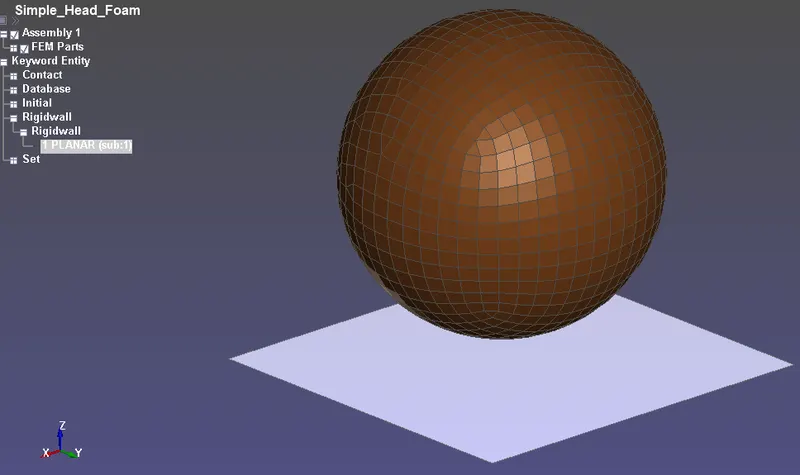
The rigid wall is translated to the exact location by the tran option present in the
Create entity--->rigid wall--->planar--->Tran--->Translate+/-.
Creation of section card:
Since the head-foam is the shell in nature, the shell section is created using the command
Model&part--->Keyword Manager--->Section--->Shell--->create.
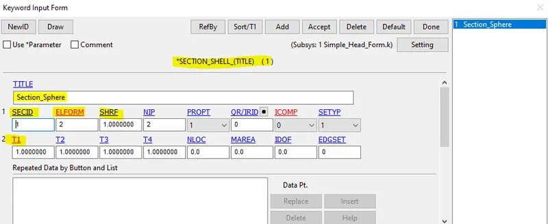
The parameters like Nodal thickness, Shear factor, and ELFORM are selected and entered the suitable values in it.
Creation of Material card:
The material used for the head-foam is *MAT_ELASTIC and the command used to create the material card is Model&part--->Keyword Manager--->MAT--->001-ELASTIC--->create.
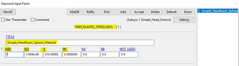
The elastic material properties like Density, Young's modulus, Poisson's ratio are inserted into the system.
Assigning Initial Velocity:
The velocity for the head-foam is inserted through the command
Model--->Keyword Manager--->Initial--->Velocity--->Create.
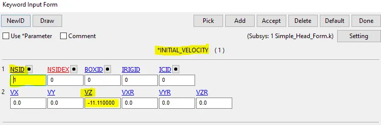
The Nodeset is created using the Create Entity--->Set data--->Set node option is used.
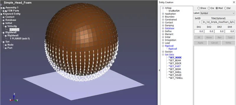
The white arrow mark shows that the velocity is acting in negative normal to the global z-axis.
Creation of Contact Interface:
The Contact_Automatic_Single_Surface is defined with the only slave. The Rigid wall is always going to act as very high stiffness with a zero deformation mode. The command used to create a contact is
Model--->Keyword manager--->Contact--->Automatic_Single_Surface--->create.
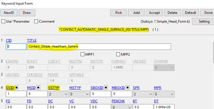
The slave set type is set to 2 which means the whole part is selected.
Output request:
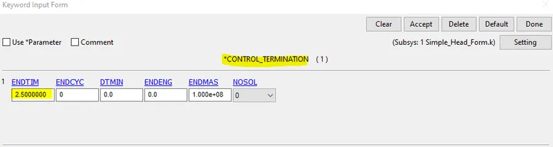
The termination time is inputted through the command
Model--->Keyword Manager--->Control---Termination. The termination time of the simulation is set to 2.5ms.
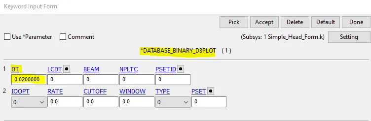
The Binary_D3_plots are obtained through the command
Model--->Keyword Manager--->Database--->Binary_D3 plot. The time interval DT is set to 0.02ms.
The ASCII plots are obtained through the command
Model--->Keyword Manager--->Database--->ASCII. The keywords like GLSTAT, RWFORC, MATSUM
are inputted into the system for the final simulation.
Model check:
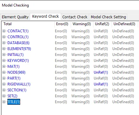
Since the model doesn't contain any errors it is ready for simulation. The final simulation is run through the command File menu--->Run LS DYNA option is used.
RESULTS:
Max Effective Stress:
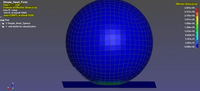
The maximum effective Stress(von-mises) is about 2.681 Gpa.
Max Effective Plastic Strain Rate:
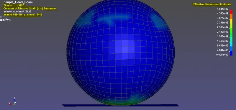
The maximum Effective Plastic Strain rate is about 0.0484(no unit).
Energy plot:
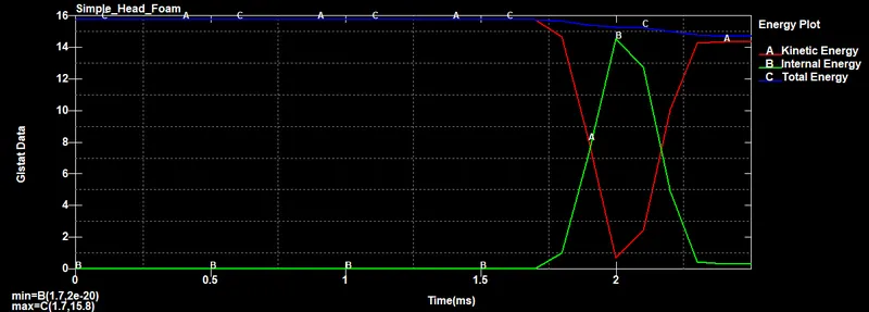
HIC-15:
The simulation span is very small so that we need to go with the HIC-15 rather than HIC-36. Here both the terms will try to capture the time span of a specific peak acceleration area in the graph. The HIC -15 value for a simple head model which impacted with a Rigid wall is measured from a node on the simple head model.
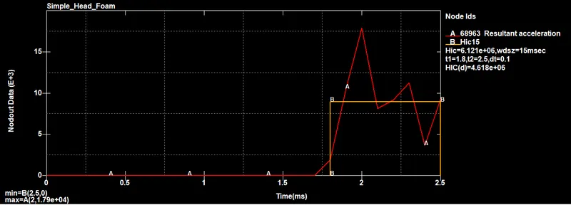
From the graph, it can be seen that resultant acceleration is increased and then decreased after the impact because the body comes to halt and again bounces back from the rigid surface at the bottom.
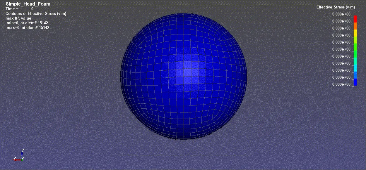
FINAL SIMULATION:
CASE-2; Child Head-foam and Rigid Wall:
Geometry setup:
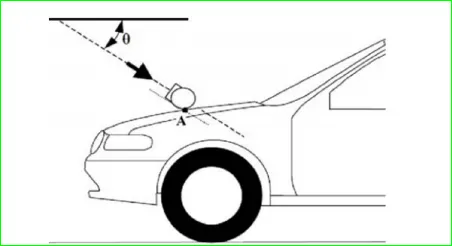
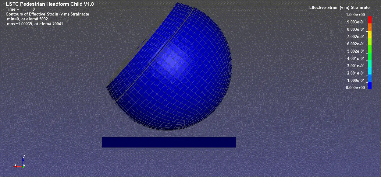
The test setup as per AIS 100. The release angle was 50⁰ for the Child head foam. The head-foam velocity at impact was 11.1mm/ms (40 km/h) for head foam. Here in this case impact point on the Rigidwall instead of a car hood.
Steps for importing Child Headform file:
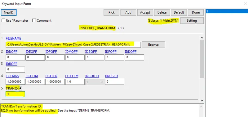
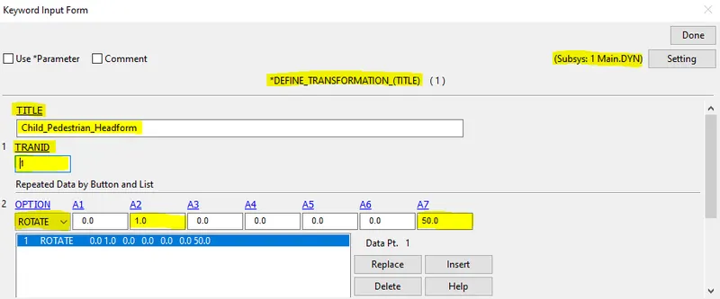
Here the *INCLUDE_TRANSFORM card is necessary for the file to be transformed and step up for the analysis. In this card, the original geometry is called through filename and defined transformation is carried out on that geometry. Transformation ID (TRANID) is set to 1 for this card. The original input file is not changed but only called for transformation.
Since the transformation of the original geometry is necessary to replicate the real impact situation. So *DEFINE_TRANSFORMATION card is used to rotate the original body about Y-axis and the A1 to A6 are direction cosines values.
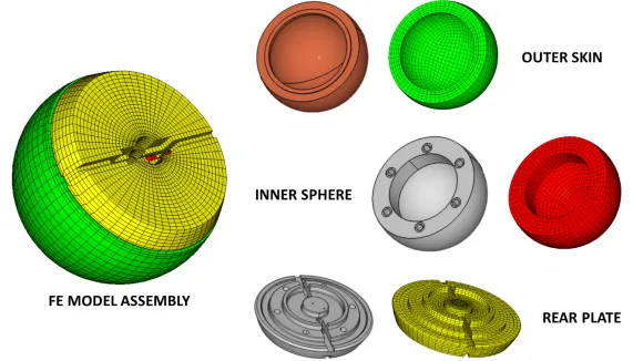
The Child head FE assembly model is imported and consists of the following parts:
The accelerometer element was placed on the rear plate inside the inner sphere which is at the same location as its counterpart in the physical head foam. There are some default keywords defined in the head-foam and that are not changed or edited in the simulation, they are listed below.
*CONSTRAINED_EXTRA_NODES_SET was used to assign contact between the outer skin and inner sphere of head foam.
*CONSTRAINED_RIGID_BODIES was used between the backplate and Sphere and accelerometer block.
*CONTACT_AUTOMATIC_SURFACE_TO_SURFACE_ID was used to assign contact between the outer skin and inner sphere.
Each component of the physical head-foam and the complete assembly were weighed to obtain their masses. Density values of each component were adjusted based on the geometry scanned and total mass weighed. The final FE child head foam model masses were 3.51 kg. These were within the allowable tolerance as per AIS 100 (+/- 0.07 kg for Child head foam).
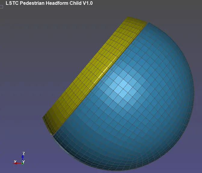
Creation of Rigid wall:
The planar rigid wall is created normal to the global Z-axis and placed 20 mm away from the rotated Head-foam geometry.
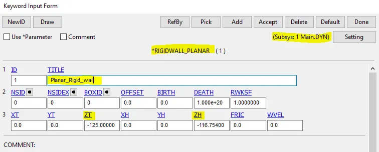
The command used for the Rigidwall creation is Model--->keyword Manager--->Rigidwall. Since it is placed normal to Z-axis only the Z-axis coordinates are entered.
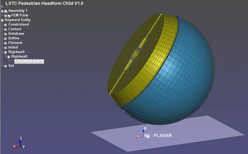
The rigid wall is translated to the exact location by the tran option present in the
Create entity--->rigid wall--->planar--->Tran--->Translate+/-
Assigning Initial velocity:
The Initial Velocity is defined along the X and Z direction to the Head-foam to impact the rigid wall. An initial velocity of -11.11mm/ms is with which the Head impacts the rigid wall but here it will be a resultant motion. So, the component motion in the x and z direction has to be calculated.
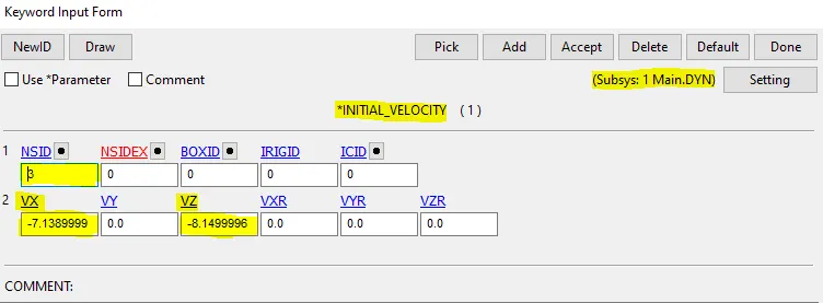
We can assume in this case that the initial velocity is 40kmph i.e 11.11 mm/ms which is a resultant velocity and so resolve the velocity component in the negative X-axis(mag. 7.1399999) and negative z-axis (mag. 8.5100002). In this case, the head is tilted at an angle of 50 deg and the values inputted are as shown above. The command used to assign the velocity is,
Model--->Keyword Manager--->Initial--->Velocity--->Create.
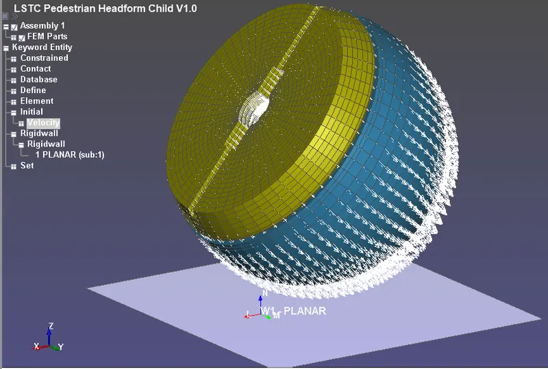
We can assume in this case that the initial velocity is 40kmph i.e 11.11 mm/ms which is a resultant velocity and so resolve the velocity component in the negative X-axis(mag. 7.1399999) and negative z-axis (mag. 8.5100002). In this case, the head is tilted at an angle of 50 deg and the values inputted are as shown above.
Output requests:
Control_Termination is defined at what time the simulation ends or the end time of the simulation. It is set to 4ms.
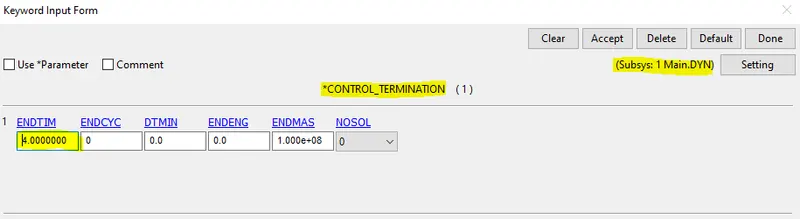
Control Time step: calculates the time step automatically for all the elements and uses the minimum value for the analysis.
TSSFAC (Scale factor for computed time step) = 0.9
DT2MS(Time step size for mass scaled solutions) = - 0.0011000.
DT2MS - Negative: Mass is added to only those elements whose time step would otherwise be less than target time step size =(TSSFAC*|DT2MS|.)
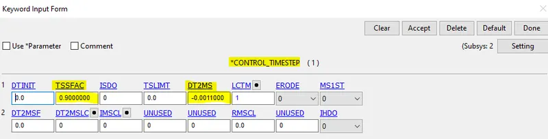
BINARY_D3PLOT - It defines the frequency at which the animation file is to be created and is set to 0.1ms
DATABASE_HISTORY_NODE A nodes on the Acceleration Block of the head were defined to measure the acceleration and calculated HIC value
ASCII_option keyword
The output request in ASCII format, The following keyword like GLSTAT, MATSUM, NODOUT, RWFORC are Activated.
Model Check:
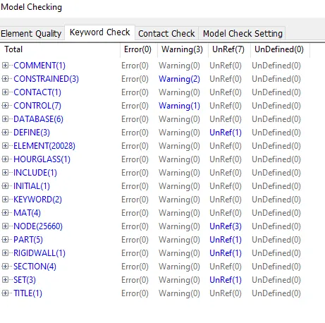
Since the model doesn't contain any errors it is ready for simulation. The final simulation is run through the command File menu--->Run LS DYNA option is used.
Results:
Effective stress:
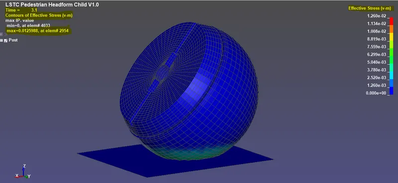
Effective Stress Plot:
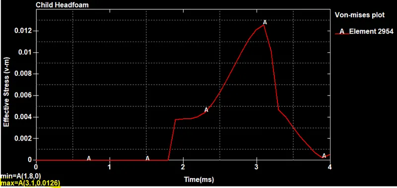
The maximum stress of 0.0126 GPa at 3.10ms at the element 2954 and after that the head-foam rebounds and decreases drastically at the end of the simulation.
Effective strain values:
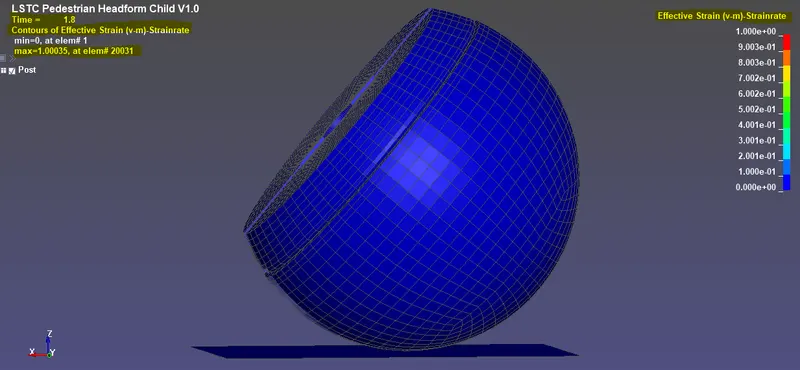
Effective Strain plot:
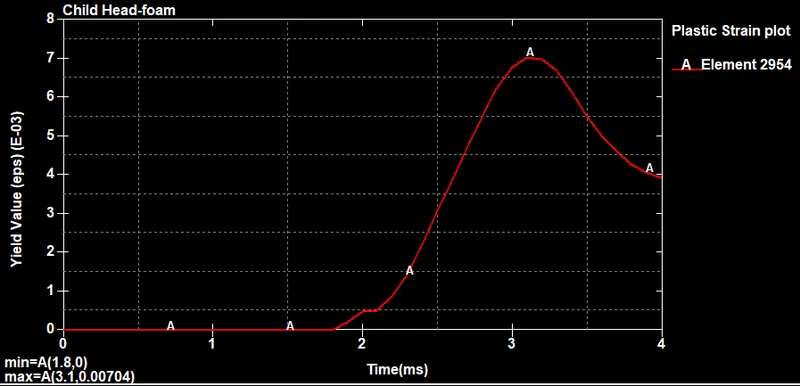
The maximum plastic Strain value is about 0.00704
In this case, the head-foam is impacting a rigid wall which is having infinite stiffness and so nondeformable, so all the stress acting on the head foam eventually form a deformation on head foam and we can see the total strain increases gradually doing the impact and drops due to Hyperelastic property of the Headfoam at the end of the simulation.
Head Injury Criteria (HIC):
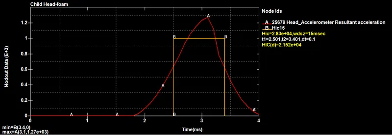
The HIC -15 value for head foam impact is measured from an accelerometer placed in the component. From the graph, it can be seen that resultant acceleration is increased and then decreased after the impact because the body comes to halt and again bounces back from the rigid surface at the bottom.
The maximum HIC value (HIC): 2.83e+04.
Energy Plot:
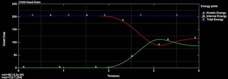
In the energy plot for head-foam impact on a rigid wall, the kinetic energy decreases as internal energy increases and the total energy remain constant. So the Laws of conservation are proved.
FINAL SIMULATION:
CASE-3; Child head-foam and Hood:
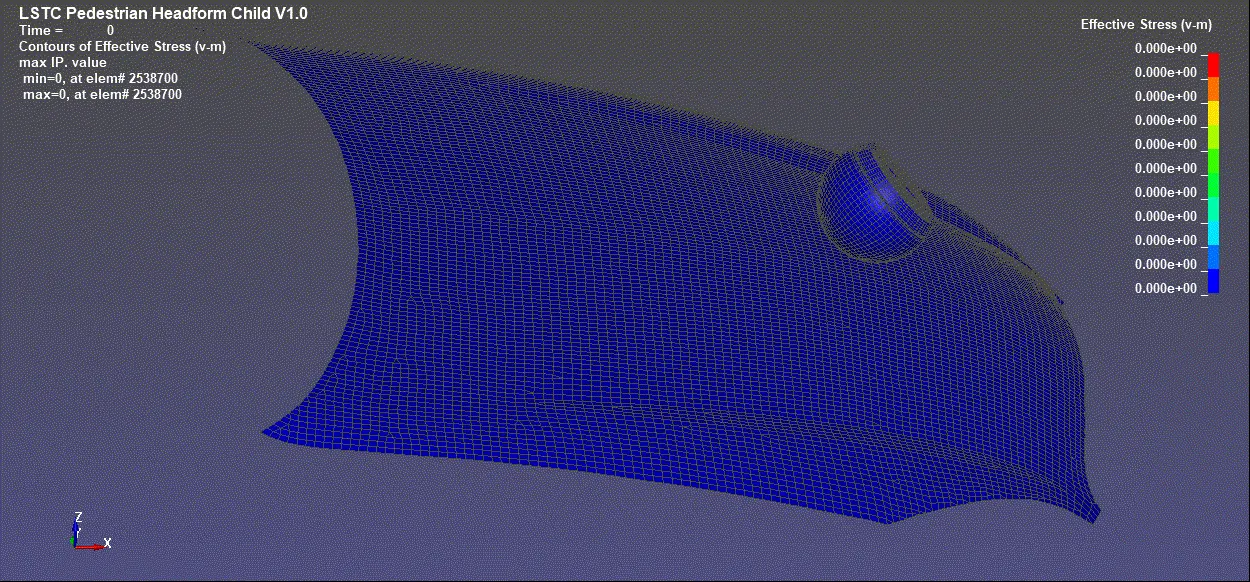
In this case, the rigid wall is replaced with a Hood to study the real-life situation of child pedestrian head impact simulation.
Importing The Geometry:
The meshed hood model in imported and The test setup is the same as per AIS 100 with the release angle was 50⁰ for the child head-foam so like the previous case we will use *DEFINE_TRANSFORMATION and *INCLUDE_TRANSFORM to define the position of the child's head.
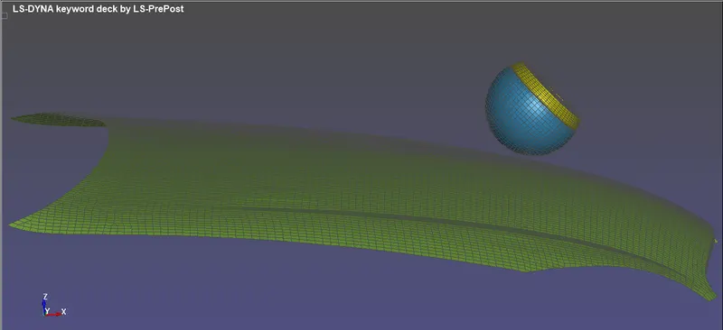
Since the Material properties and section properties are pre-defined only for the child head assembly and have to be defined for the car hood.
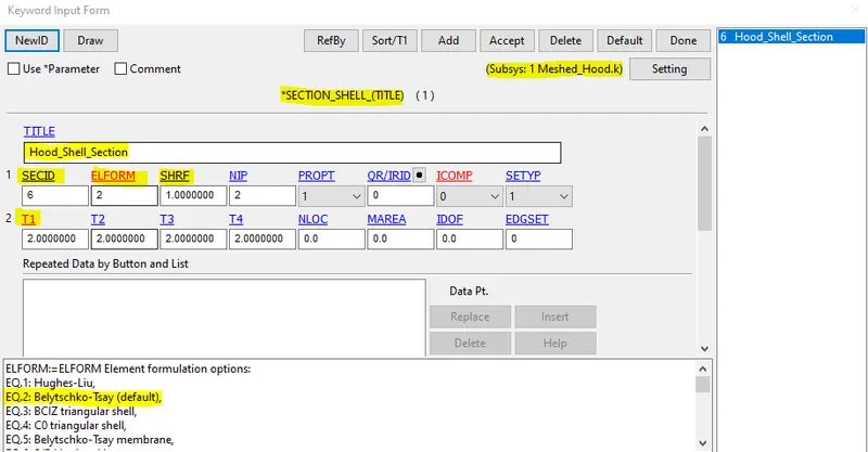
Creating Section card:
Since the head-foam is solid in nature, and the Car Hood are meshed using 2d element we will define them with SECTION_SHELL card. The command used to create the section card is,
Model&part--->Keyword Manager--->Section--->Shell--->create.
Creating Material card:
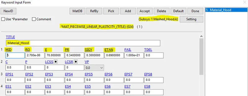
We will use Aluminium Material Properties for the Car Hood. Although many material models exist for metals, one of the most robust models is *MAT_024 or *MAT_PIECEWISE_LINEAR_PLASTICITY. This material model is recommended and it is the starting point for elastic-plastic simulation of metals and general plastics since it can also handle viscoelastic behavior (i.e., strain-rate dependency). The command used to create this is
Model&part--->Keyword Manager--->MAT--->024_MAT_PIECEWISE_LINEAR_PASTICITY.
Creating Contact Interface:
An AUTOMATIC_SURFACE_TO_SURFACE contact has been defined between Hood and head-foam. Hood as master and the head foam as a slave. As the head foam has 5 components in it, the slave node-set type is given as Part Set ID and hood as master segment type is also given Part set ID. The command used to create contact is
Model--->Keyword manager--->Contact--->Automatic_Surface_to_Surface--->create.
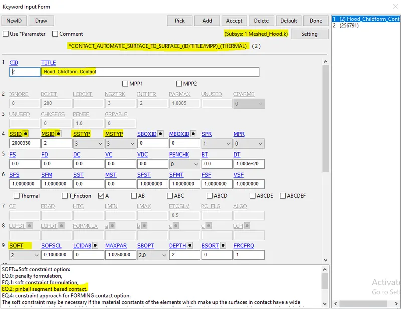
Since the skin of the Head-foam is hyper-elastic material and the hood is metal in nature. So, when two different materials came into contact, the segment-based contact algorithm is introduced(i.e., pinball segment-based contact).
Assigning initial velocity:
The Initial Velocity is defined along the X and Z direction to the Head-foam to impact on the car hood. An initial velocity of 11.11mm/ms is with which the Head impacts the rigid wall but here it will be a resultant direction. So, the component motion in the negative x and negative z-direction has to be calculated.
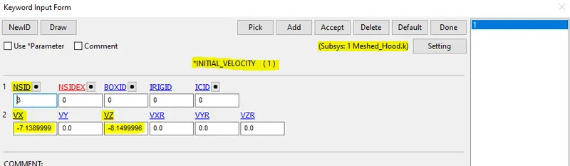
Model--->Keyword Manager--->Initial--->Velocity--->Create.
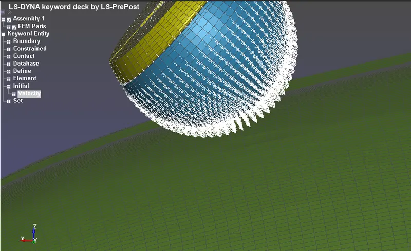
We assume in this case the initial velocity is 40kmph i.e 11.11 mm/ms which is a resultant velocity and so resolve the velocity component in negative x (mag. 7.1399999) and negative z-axis (mag. 8.5100002). In this case, the head is tilted at an angle of 50 deg.
Creating Boundary SPC card:
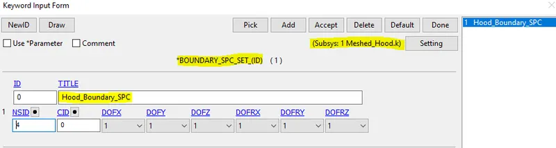
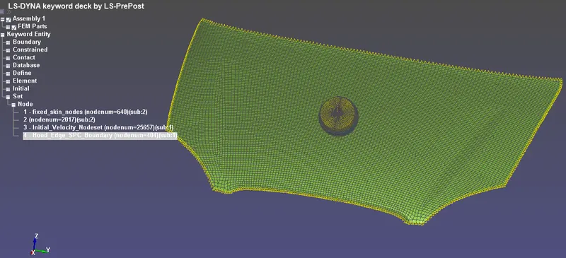
The Boundary SPC is defined for the Hood to constraint all the Degree of Freedom(DOF) for the set of nodes (NSID) on the edges of the hood.
Output requests:
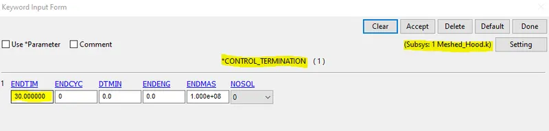
Control_Termination is defined at what time the simulation ends or the end time of the simulation. It is set to 30ms.
Control Time step: calculates the time step automatically for all the elements and uses the minimum value for the analysis.
TSSFAC (Scale factor for computed time step) = 0.9
DT2MS(Time step size for mass scaled solutions) = - 0.0011000.
DT2MS - Negative: Mass is added to only those elements whose time step would otherwise be less than target time step size =(TSSFAC*|DT2MS|.)
BINARY_D3PLOT - It defines the frequency at which the animation file is to be created and is set to 0.5ms.
DATABASE_HISTORY_NODE /SHELL. A node/element on the Acceleration Block of the head was defined to measure the acceleration and calculated HIC value.
ASCII_option keyword
The output request in ASCII format, The following keyword like GLSTAT, MATSUM, NODOUT, RWFORC and ELEOUT are Activated.
Results:
Effective stress Hood:
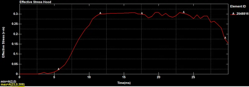
The maximum value of Effective stress in the hood is 0.3087GPa at the element 2547996.
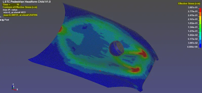
Effective stress plot for Hood:
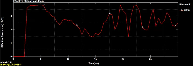
Effective stress plot Head-foam:
The maximum Effective stress value in the head-foam is about 0.00384GPa.
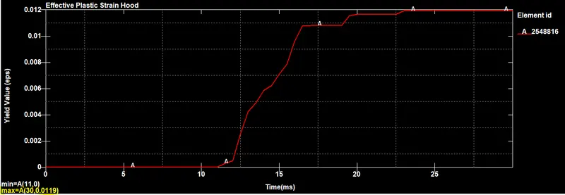
Effective Plastic strain plot hood:
The maximum Effective plastic strain value for the hood is about 0.0119.
In this case, the hood is defined with a Piecewise linear plasticity material card which is deformable, so during the head foam impact, the hood deforms significantly and reduces stress and strain on the head foam, and saves the child pedestrian from huge impacts. The effective plastic strain showed on the graph is for the hood part because the deformation in the head-foam is nearly zero or no deformation.
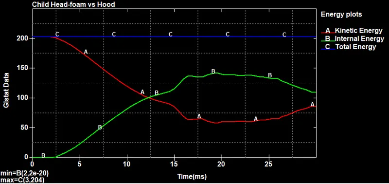
Energy plot:
Here since the hood deforms and kinetic energy decreases and the internal energy increases gradually but in the previous study we can able see an abrupt change in these energy values at impact.
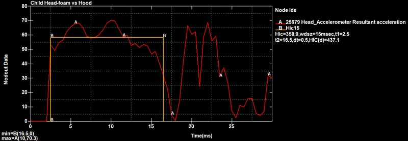
Head Injury Criteria (HIC):
The HIC -15 value for head foam impact is measured from an accelerometer placed in the component. From the graph, it can be seen that resultant acceleration is increased and during the initial impact stage decreased after 15ms because the hood deforms gradually and slows down the head velocity, not in a quick time but in a margin of time which will save our head from several injuries.
The maximum HIC value is about 358.9 and the maximum HIC(d) is about 437.1.
FINAL SIMULATION:
Manual calculation:
Trying to find the HIC value manually:
From the above graph we can take time span = t2 - t1
= 16.5 - 2.5
= 14.0ms
Equation to find the HIC value is,
Here,
`t_2-t_1=`14.0ms = 14.0/1000 s
HIC = ([(1/14.0)*58.4*14.0]^2.5)*[14.0/1000]
HIC = 364.89, which is nearly equal to the value that we got from the solver in case-3. This a real-life crash situation.
Observation from the results:
First case; Simple head model and rigid wall:
The simple head model was defined with MAT_ELASTIC material card which implies the material is pure elastic that’s why the max stress is only there in the time of the impact there is no significant deformation in the simple head geometry. That’s why the HIC values are too high.
Second case: Child head-foam and rigid wall:
The standard model of the child head-foam with proper material was used, Since the rigid wall is undeformable so the total stress is transferred to the head and deforms the head foam geometry severely the HIC values are lower than case 1.
Third case: Child head-foam and bonnet:
With the standard head model but in this case, it impacts on the car hood to study the real-life situation the hood was defined with a piecewise linear plasticity material model (Mat_024) which is a deformable model so during the impact the hood deforms significantly and reduces stress and strain on the head foam and thus reduces HIC values and the value are lower than case 2.
CONCLUSION:
Thus the Child pedestrian Head-foam material model with the hood is compared with the different crash simulations and the results are compared using the plots with various parameters. Three cases are compared with each other and the real-life crash scenario is followed on the model to find the maximum HIC value during the impact. We also compared the manual calculations of HIC with the plot results from the simulation. Bothe the results match approximately with each other.