2D meshing on the instrumental Panel using ANSA
OBJECTIVE:
The main objective of this challenge is to achieve the good mesh quality for the given component. The CAD geoemtry is cleaned with the useful tools in the ANSA and the mid surface is extracted. Then the new midsurface is subjected to meshing where the component is discritesized and then good flow, quality and geometry capturing is done. Finally the thickness is assigned to the meshed component.
2D SHELL MESH:
The 2D Mesh module is used to construct two-dimensional finite element meshes. The mesh consists of nodes that are grouped together to form elements.
In 2D meshing there are some element types involved to decide what type of analysis to be done on the model, they are
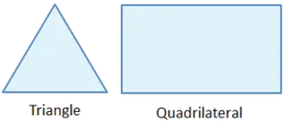
Tria element:
This cell shape consists of 3 sides and is one of the simplest types of mesh. A triangular surface mesh is always quick and easy to create. It is most common in unstructured grids.
Quadrilateral/Quad element:
This cell shape is a basic 4 sided one. It is most common in structured grids. Quadrilateral elements are usually excluded from being or becoming concave.
INPUT MODEL:
The given input model is Instrument panel. There are five steps to acheive the quality mesh in the model, they are
Cleaning the geometry,
Extracting the midsurface,
Meshing,
Quality checking,
Assigning thickness.
CLEANING THE GEOMETRY:
The geometry is cerified with the option called checks manager. It is in the
menu bar--->tools--->checks--->geometry.
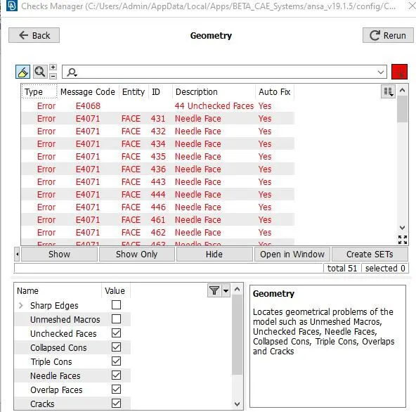
The checks manager used to say all the errors in the model and listed it in the window according to the list of input clenup parametres we given.
Then the model is cleaned with the unwanted lines, points and removing the unwanted surfaces using the following tools.
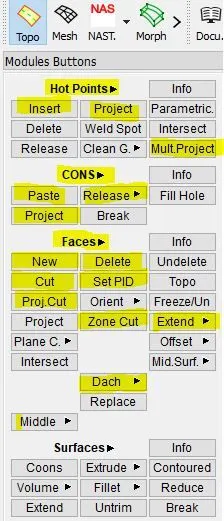
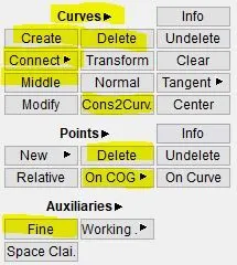
The above mentioned tools are used for the geoemetry cleanup process and the most frequently used tools are listed below,
topo--->hot points--->insert/project,
topo--->CONS--->paste/release/project,
topo--->Faces--->new/delete/cut/dach,
topo--->curves--->create/cons2curve/connect,
topo--->auxiliaries--->fine.
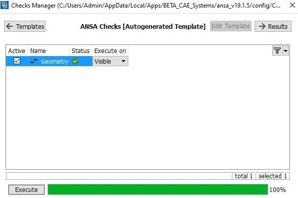
After the checks manager verification, the model is subjected to midsurfacing process.
EXTRACTING THE MIDSURFACE:
Though it is a plastic component it has variable thickness all over the component. So the component is not subjected with the automid option. The only tool to take midsurface for the variable thickness components are offsetting.
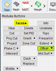
For offsetting there are two steps followed, they are
offsetting the outer surface,
offsetting the ribs and the doghoses.
The outer surface is having an uniform thickness and the ribs, doghoses are having different thickness. The command used for the offset is topo--->faces--->offset.
Before offsetting the thickness of the component is checked in various places and according to that data midsurface is done.
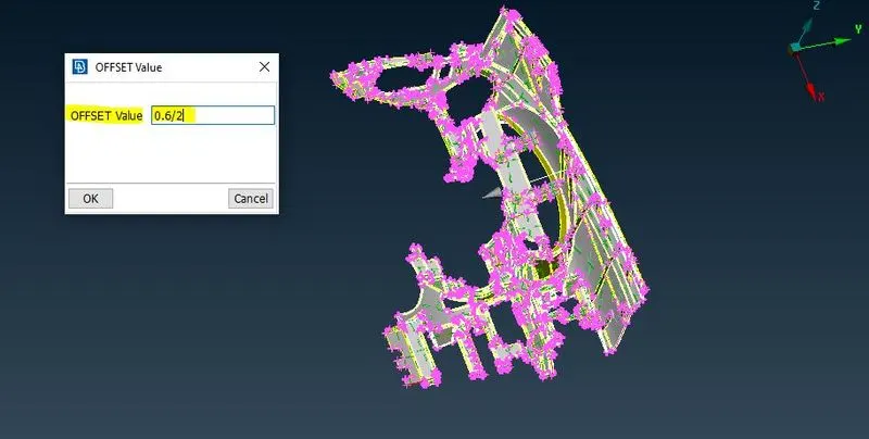
The input value is entered in the dialouge box and the new mid component is saved seperately in a new PID in the dataview tab.
First the ribs are defeatured using the command topo--->faces--->dach.
Then the one side of the defeatured face is offseted to the middle of the component using the command topo--->faces---> offset.
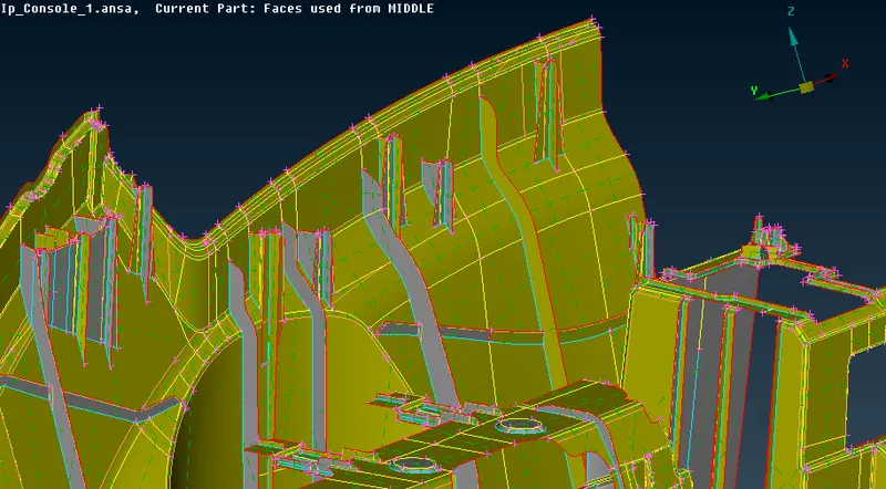
There are triple cons present in the model because it is sharing more than two surfaces. The extend option is used to connect the rib with the surface. The command used for the extend is
topo--->faces--->extend.
Finally the doghoses are taken mid using the command callend curves. This command extracts the middle line from the doghose. The command for this process is topo--->curves--->create/middle.
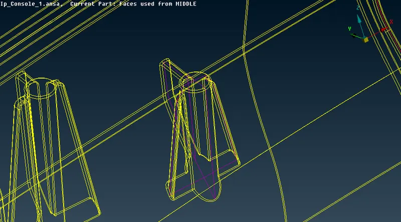
The above mentioned figure is the example of how the midsurface is done for the doghoses. The yellow lines are shared edges and the purple lines are curves created for the midsurface. The same procedure is followed for all other doghoses. Then the new mid surfaced doghoses are extended to the surfaces using extend option.
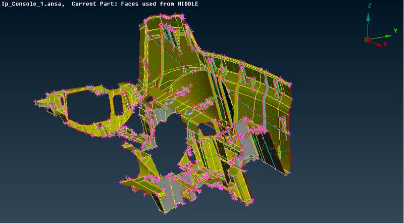
The component is divided into similar parts and set into a PID for easy meshing. The command for this option is topo--->faces--->set PID.
MESHING:
After the middle surface extraction the geometry of the model is checked again for the error. Then the meshing is done through the command
menubar--->mesh--->mesh generation--->best.
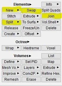
After the mesh was deployed to the surface, the element edit options like split, swap, join, paste, are used.
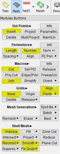
For whole modification of the mesh present in the surface mesh edit options like improve, reconstruct are used.
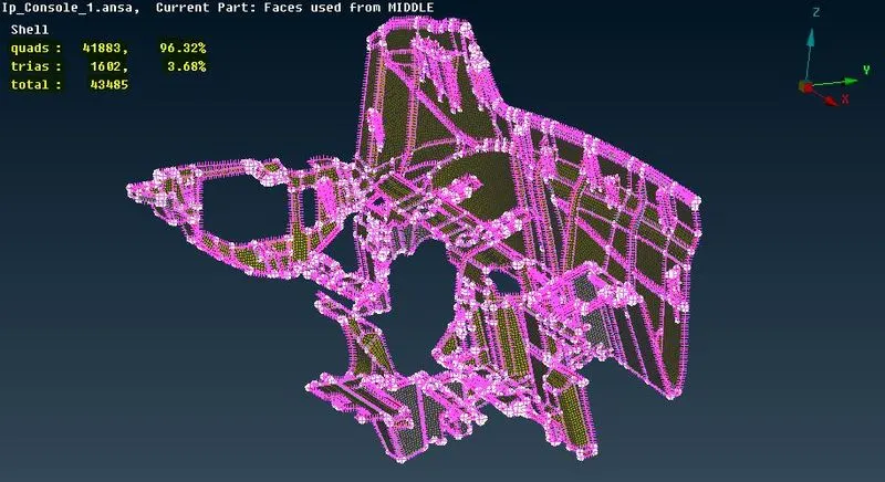
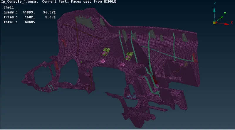
The top left corner of the figure shows the total no.of. quad and tria elemnts present in the component.
QUALITY CHECKING:
The quality checking is the most important step in the meshing. It helps in the analysis part to finish the analysis faster. The element quality is checked through hidden option in the drawing style in the below deck.
The below mentioned are the input quality parameteres that is to be followed in the meshed model.
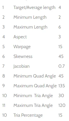

This specific tool is used to find the off elements that violates the mesh quality and cleared using the above mentioned mesh editing tools.
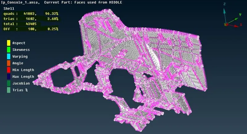
The left top corner of the window show the off elements. The total number of 108 off elements are present in the component. This happens when the geometry capturing is taken into account.
The final check is the edges. The important quality checking is edges because each and every element in the model should be connected with each other to obtain the accurate results in the analysis part.
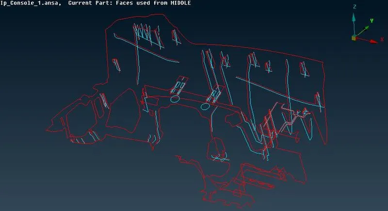
The red lines shows the free edges in the component and the blue lines are shared edges in the component.
ASSIGNING THICKNESS:
The elements that are associated with the CAD is assigned a thickness value. For that the each and every part of the model is put in the new PID using the tool topo--->faces--->set PID.
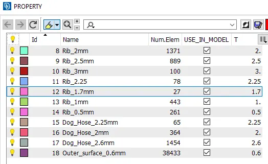
By switching to the PID mode the thickness assigned components are displayed with different colours.
Each and every time the ANSA itself assign a thickness to the newly created component.
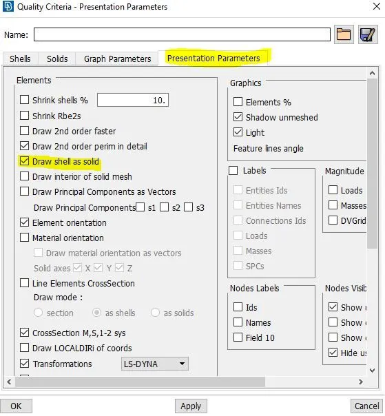
The command for assigning the thickness to the component is from the option through
menubar--->tools--->quality--->presentation parametres--->draw shell as solid option is used.
The last step is to check the percentage of tria elements in the model and it is available in the top left corner of the window.
The total number of tria elements present in the model is about 3.68%(1602 nos.).
CONCLUSION:
The given plastic component with variable thickness is meshed by cleaning the geometry, taking the midsurface and then the quality of the mesh is improved using some tools in the ANSA. The minute features present in the model are captured accurately and meshed with the appropriate tools in the meshing tab. The thickness for the meshed model is verified and the qaulity of the mesh also checked.