Mobile phone Drop test using LS-DYNA
OBJECTIVE:
The aim of this challenge is to simulate the drop test of the cell phone falling in the rigid plate using the LS-DYNA. The model is set with suitable input parameters. After running the model, the plots are reviewed.
PROCEDURE:
There are three steps to be followed to achieve the simulation of the drop test, they are
Model setup,
Output requests,
Results.
MODEL SETUP:
The model setup is nothing but, the input model(keyword file) is studied and inputted with the suitable parameters in LS-DYNA PREPOST deck, they are as follows
Title,
Part creation
Assigning material cards,
Section creation,
Contact interface,
Initial velocity,
Boundary conditions.
TITLE:
A suitable title is given to the model using the command
Right-side toolbar--->model--->Keyword manager--->Title.
PART CREATION:
In LS-DYNA part is more important because each and every assembly of the component is addressed here. To create a part
Right-side toolbar--->model--->Keyword manager--->part command is used.
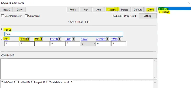
On the right side of the window, part names are displayed. Each part has its own PID, TITLE, SECID, and MID.
To view the part in the assembly, a browser tree on the top left corner in the LS-DYNA is used.
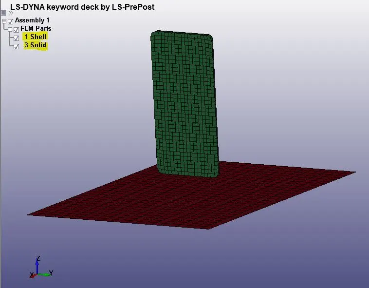
It shows the assembly, FEM parts, input parameters, etc. In our challenge there are two entities are used they are plate(shell), phone(solid). When the model is opened it consists of both shell and solid elements in the plate. To run the simulation either shell or solid is used. I used the shell element type because of easier computation.
ASSIGNING MATERIAL CARD:
To assign the material to the parts separately, the command used is
Right-side toolbar--->model--->Keyword manager--->Materials
--->024_piecewise_linear_plasticity card is used.
*Mat_024_Piece_Wise_Linear_Plasticity:
This is Material Type 24, which is an elastoplastic material with arbitrary stress as a function of strain curve and arbitrary strain rate dependency can be defined. Failure based on the plastic strain or a minimum time step size can be defined. The input values like density, young's modulus, Poisson's ratio, yield stress, and tangent modulus are inputted to the system.
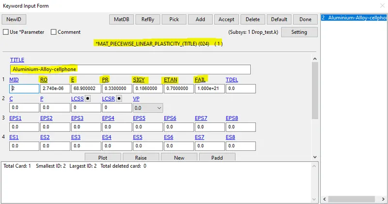
The failure card flag with a non-zero value entered into the system. This means when the plastic strain value exceeds the failure value, the corresponding element will be deleted from the system.
Similarly, the same procedure is followed for the other part to assign the material property card. But only the material card is changed to rigid type.
Right-side toolbar--->model--->Keyword manager--->Materials--->rigid command is used.
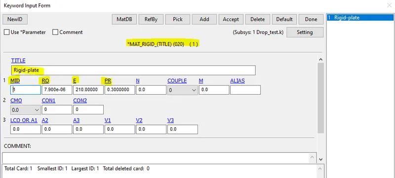
*Mat_020_Rigid:
This material type is because we don't want the results for the plate at the bottom. The plates ate constrained at four ends and no output is viewed in the plate. This material card also needs mass density, Poisson's ratio, and Young's modulus.
CREATING SECTION:
In this section, the element formulation, integration rule, nodal thicknesses, and cross-sectional properties are defined. Each section is defined by a unique number called SECID is used with the appropriate title for the section. In our case two sections are created, they are solid section, shell section.
Solid section:
The command used to create the section is
Right-side toolbar--->model--->Keyword manager--->section--->solid.
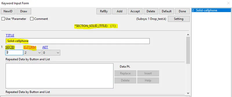
The main option is element formulation and it is selected as 2. It means it avoids the pressure locking and assumes that the pressure is constant throughout the element during the nearly compressible flow of the elements.
Shell section:
The command used to create the section for shell elements are,
Right-side toolbar--->model--->Keyword manager--->section--->shell.
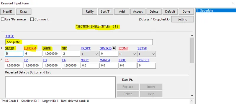
The parameters like element formulation, thickness, and SECID are inputted to the plate.
CONTACT INTERFACE:
The objective of inputting the contact is to see how the nodes are reacting to external forces acting on the body. This gives us the exact solution to the problem. The surface-to-surface contact interface is used for the simulation. The command used for creating the contact interface
Right-side toolbar--->model--->Keyword manager--->Contact--->Automatic-surface to surface type is used.
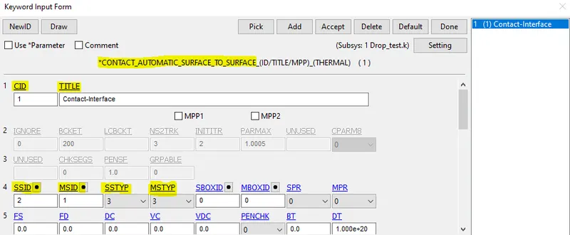
To input the slave and master segment, the phone part is assigned as the slave segment and for the master segment, a rigid plate is used. The slave and master are inputted as partID's.
INITIAL VELOCITY:
The objective of this challenge is to drop the phone from a certain height at some speed and see the results of the stress and strain rates in the phone. Since the distance between Cellphone and plate is around 20 mm so velocity is
`V=sqrt2gh`
Right-side toolbar--->model--->Keyword manager--->Initial--->velocity command is used.
The velocity of 5.94mm/ms Is given to the Mobile Phone. As the phone is dropping along a negative z-direction so Vz= -5.94 mm/ms is given as initial velocity by selecting all the nodes of the Mobilephone.
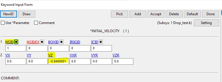
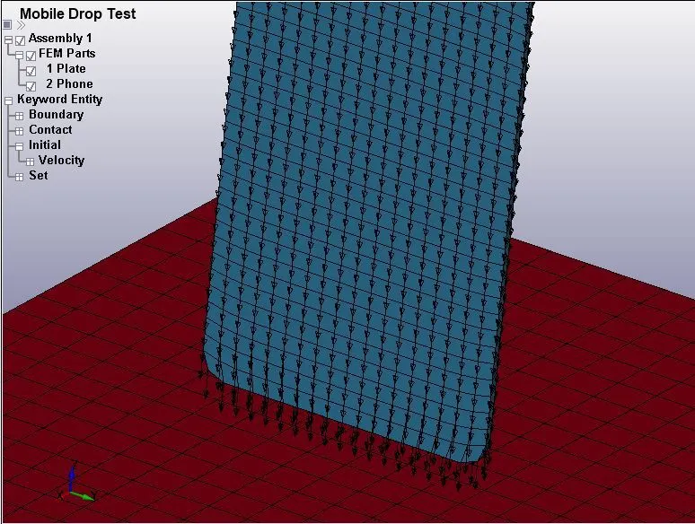
The arrow mark in the image shows that all the nodes in the phone part move in the negative Z-direction at a speed of 5.94mm/ms
BOUNDARY CONDITIONS:
As the plate is Not Fixed it's Fixed Using SPC ( Single Point Constrained )Nodes at each Corner of the plate. To Create Spc go to
Right-side toolbar--->Create entity---> Boundary---> Spc---> Create .
Select Four Nodes At each Corner and Their DOF's are set to 1, Dof=1 means It's movements are Locked in all Direction both translationally and Rotationally.
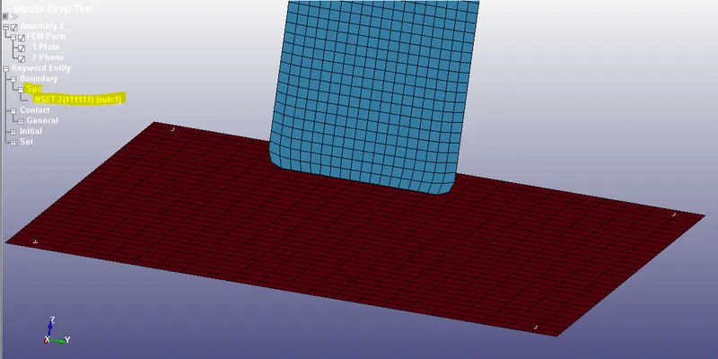
The white color marks at four corners denote the constrained nodes of the rigid plate. The right side of the window shows the nodesetID with all the translational and rotational movements are locked.
CONTROL CARDS:
Control cards such as Control Termination, Control energy are specified. Termination time defined by using *CONTROL_TERMINATION card
To set control card
Right-side toolbar--->model--->Keyword manager---> control---Termination command is used. The simulation time is set to 5ms.
OUTPUT REQUESTS:
To view the results of Simulations Following Steps are Specified.
Go to Keyword Manager---> Database--->ASCII--->GLSTAT with DT 0.5.
GLSTAT(GLOBAL STATICS)card is enabled with 0.5 output time interval which gives global energy data like Kinetic Energy, Internal Energy, and other types of energy.
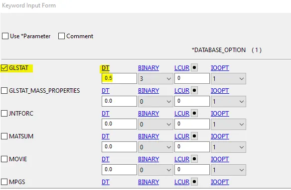
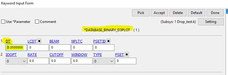
Similarly, to get the results of the Binary plot,
Keyword Manager--->Database--->Binary D3plot--->DT 0.5 It prints the Output file at each 0.5ms. The D3PLOT card gives animation and other post-processing data after the simulation.
MODEL CHECK:
After setting all the parameters to run the simulation, it is necessary to check the model to avoid instabilities in the simulation. The command used is
Right-side toolbar--->model--->Model check--->keyword check.
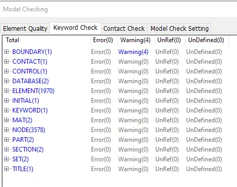
Once the model is no errors we are good to go with simulation.
Simulation:
Save the Keyword In a separate Folder And Run the Simulation In LS-Dyna manager.
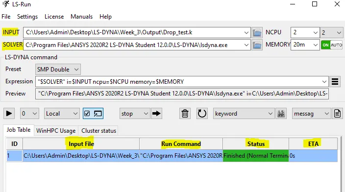
After Running the Simulation Open the Binary D3plot file in Ls Dyna pre-post through the command File--->open--->LS-DYNA binary file.
After opening the simulation file, the stress like vonmises stress, energy plots like Kinetic energy, internal energy are plotted.
VON MISES STRESS
MAX STRESS
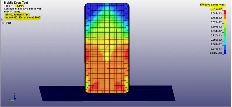
The Maximum Stress acted on the element is 9.316gpa at 3.2496 sec in element ID 7005.
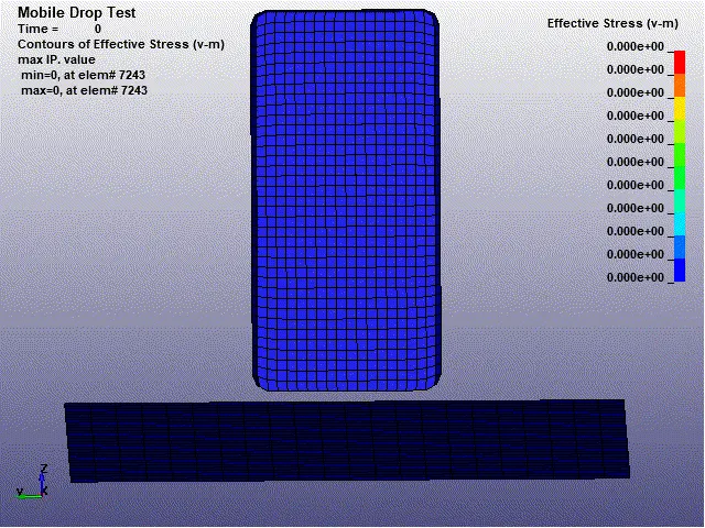
The Minimum stress on the element is 0.000+00 at element ID 7243.
ENERGY PLOT:
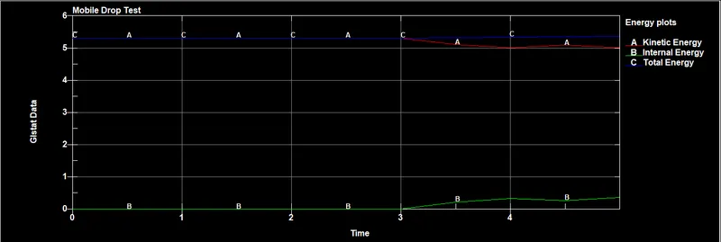
There is no impact till 3ms, After 3ms we can see Deflection in Both Kinetic energy and Internal energy. As we can see the Internal energy produced By the Rigid Plate is Exactly the inverse of the same as the Kinetic energy. The Total energy is remaining constant Throughout the process. The law of conservation of energy is satisfied.
FINAL SIMULATION:
CONCLUSION:
By running the simulation for drop test, the keyword file is generated and stresses like von mises stress, energy plots are analyzed through the LS-DYNA PrePost deck.