Assignment 2
1.CALCULATING THE SPEED OF SOUND IN THE STEEL RAIL:
TIME STEP(dt):
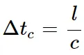
The time step (dt) is the time required for the shockwave (speed of sound) to propagate across the smallest distance in an element.
Only one time step is applied and passed to the only one element or node otherwise the calculation is unstable.
Based on the material property the speed of the sound is approximately 340m/s at vaccum.
The stability of the computation is based on the size of the element and the speed of the sound propagation.
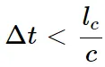
where,
Delta_t=Critical time step,
l_c=critical length,
c=speed of the sound.
CHECKING THE MATERIAL PROPERTIES :
The density and the young's modulus of the material is taken into account for the calculation.
E = 210Mpa = 210N/mm^2.
Rho=0.0078g/mm^3
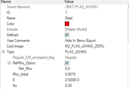
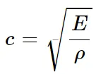
c=root2(210000/0.0078)
c=5188.745
c=5188.745m/s or 5188.745mm/ms.
2.CALCULATION OF TIME TAKEN FOR THE SHOCK WAVE TO TRAVEL FROM ONE END TO THE OTHER END OF THE RAIL:
The length of the rail is about 1000mm.
 = 1000/5188.745
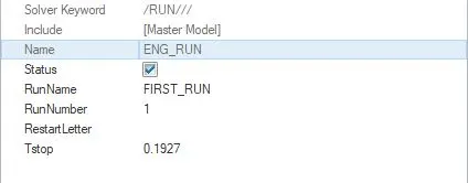
=0.1927 ms
The time taken for the shock wave to travel from one end to the other end of the rail is about 0.1927 ms.
3.TIME FOR SOUND TO TRAVEL THE LENGTH OF THE RAIL:
It is same as the previous question that the time taken to the shock wave (sound) to travel from one end to the other is about 0.1927ms.
4.Edit the engine file so that the stress wave can be monitored, moving from one end of the rail to the other during impact -this will require a termination time equal to the time it takes for the sound to travel the length of the rail(set on/RUN card):
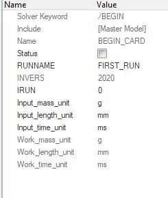
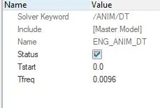
The main objective of this is to run a simulation in RADIOSS with an animation of 20 steps and run time of 0.1927ms.
So the calculation be like;
Animation o/p time = Total time/no.of steps
=0.1927/20
=0.0096
PROCEDURE:
1)Importing the Input file:
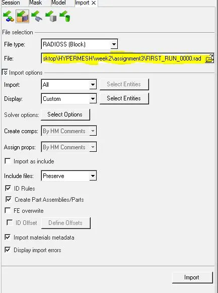
This tab shows us file path from where the _0000.rad format file is opened.
2)Assigning the values to the materials:
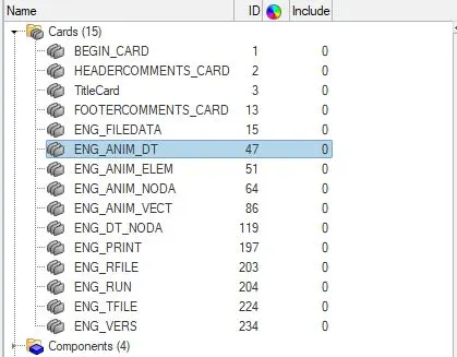
From the above calculation the animation file frequency value and the stop time value for the simulation is assigned.
3)Running the simulation:
To run the simulation we used the command Analysis--->RADIOSS--->Save the directory file and click RADIOSS.

4)Results:
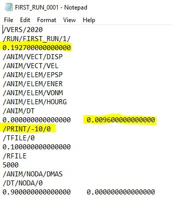
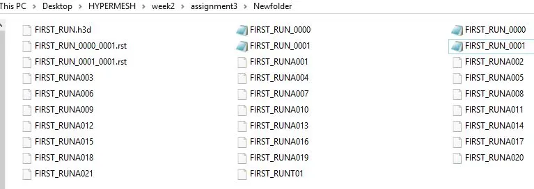
From the above image the print value is 10. It is nothing but the amount of iterations that run and saved in the _0001.rad format file in the local directory.
7.HEX MESH AND TETRA MESH IN 3D MESH:
3D MESH:
A 3D mesh is the structural build of a 3D model consisting of polygons. 3D meshes use reference points in X, Y and Z axes to define shapes with height, width and depth.
The polygons used are typically quadrangles or triangles; these geometric shapes can be further broken down into vertices in X, Y, Z coordinates and lines. They all have triangular and quadrilateral faces.
There are four types of 3D mesh elements, they are.
Tetrahedron,
Quadrilateral pyramid,
Triangular prism,
Hexahedron.
TETRA MESH:
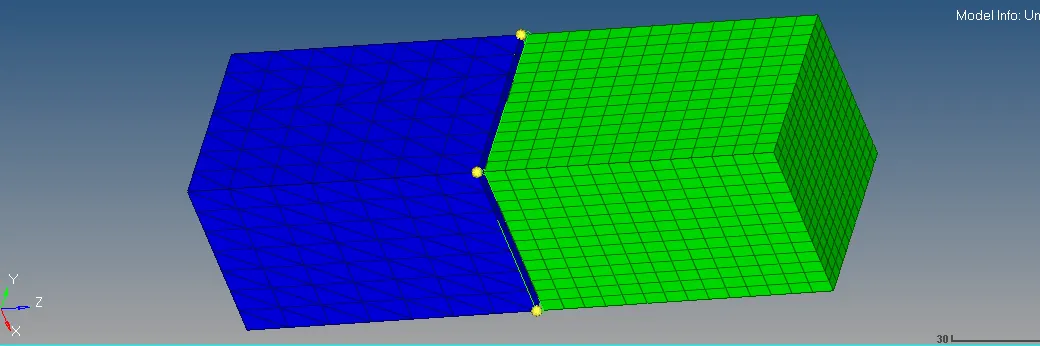
A tetrahedron has 4 vertices, 6 edges, and is bounded by 4 triangular faces. In most cases a tetrahedral volume mesh can be generated automatically.
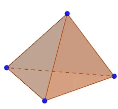
Tetrahedral is a four- nodded solid element which can be generated through the tria element by creating a volume and also through the existing volume of the geometry. These elements are used where the geometry has high thickness and complexity.
HEX MESH:
A hexahedron, a topological cube, has 8 vertices, 12 edges, bounded by 6 quadrilateral faces. It is also called a hex or a brick. For the same cell amount, the accuracy of solutions in hexahedral meshes is the highest.
HOUSING:
1)creating 2D mesh:
For tetra meshing the 2D auto mesh is devoloped over the surface first. Then only the tetra mesh is applied to the surface.
After creating the mesh over the 2D mesh the tria elements are deleted all over the entity.
There are two parts meshed seperatedly.
cover part:
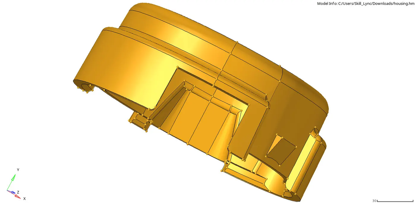
After the input is opened the 2d mesh id done through 2D--->Automesh--->Create.

After that the tetra mesh is done through 3D--->Tetra mesh--->Selecting the surface and adjust the tetramesh input parametres.
It includes Tet collapse and min mesh size.

TET COLLAPSE:
Tet collapse is one of the quality parameters, which will be checked while generating Tetrahedral elements. It can be calculated by measuring the distance of a node from the opposite face, then each of the four values will be divided by the Square root of the opposite face's area.
To get the accurate tetra mesh the value of the tet collapse should be 0.15.

Meshing:
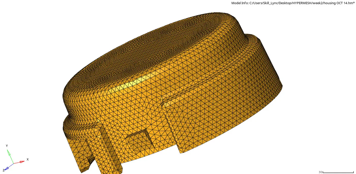
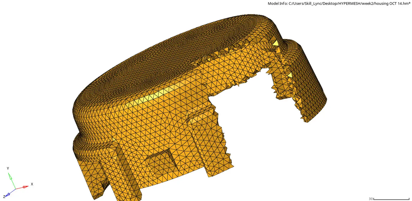
After creating the tetra mesh the 2D mesh id deleted using the delete option.
HEXA MESH:
The same procedure is followed for the hexa mesh.
First the 2D mesh is created and offsetted.
After creating the mesh the 2D mesh is deteled using the delete option.
Tools used in the mesh creation:
In the 2D panel, the option like solid map, linear solid, elem offsetting, spin options are used.
By using this options proper mesh is creted.
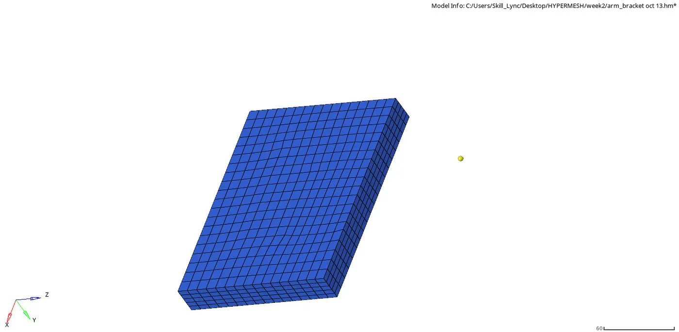
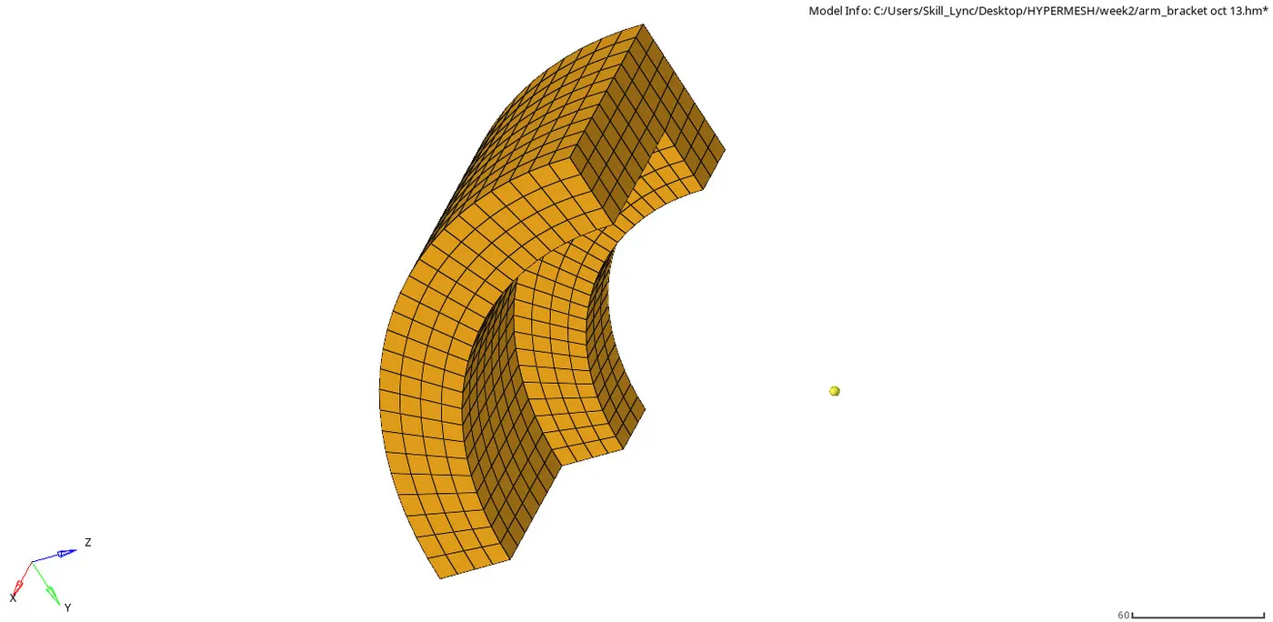
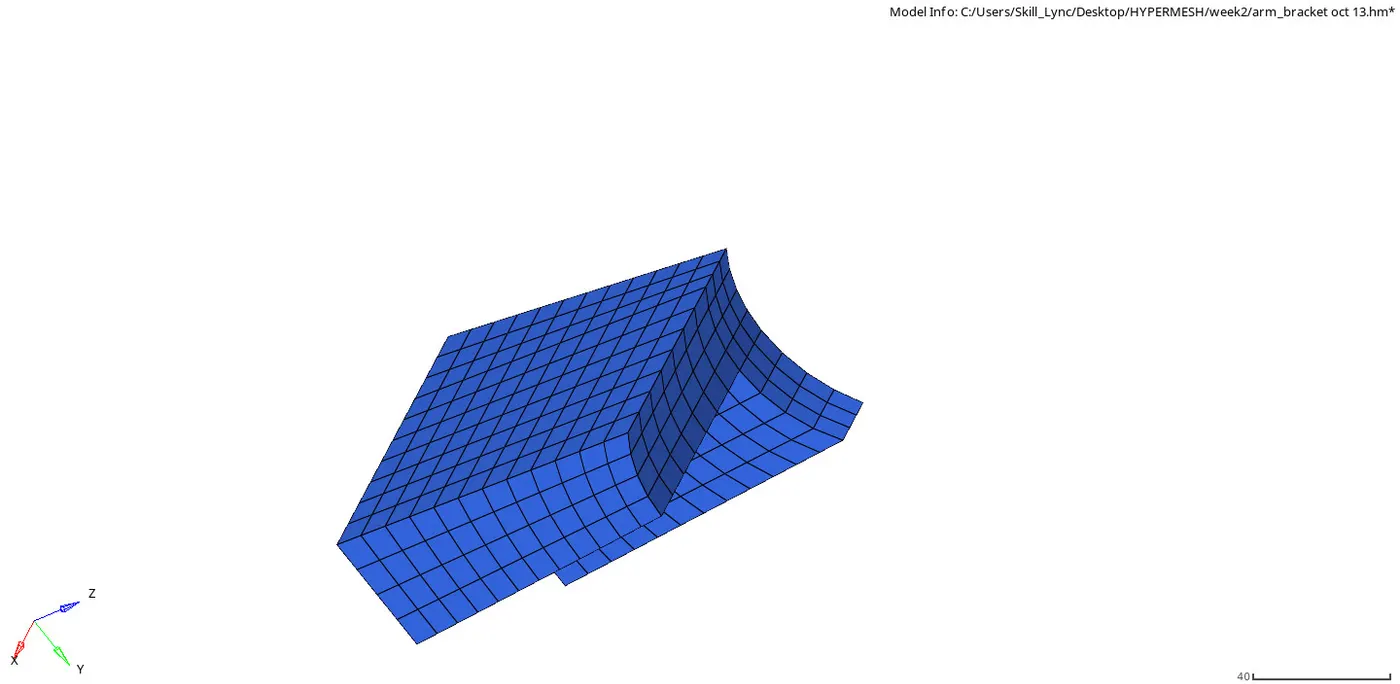
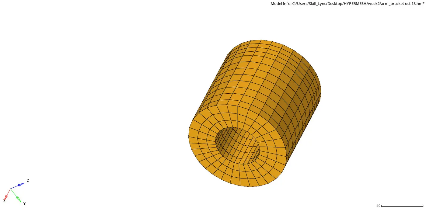
There are four parts are divide into,they are;
base, arm_straight, arm_curve, boss.

The highlighted are used for creatin the hexa mesh.
Base:
Arm curve:
Arm straight:
Boss:
OUTPUT FILES LINK:
https://drive.google.com/drive/folders/1u3mc9g-ue6QgqIB-ZqdfhH1hCRnZdvJW?usp=sharing