Calculation of the Stretch Ratio by comparing the ELFORM (-2,-1,1,2) with Ogden_Material Model.
OBJECTIVE:
Create a block of 10mmx10mmx10mm dimension with 10 elements for each direction and use the material card attached (Ogden_Material.k) that is representative of the material properties. Use appropriate boundary conditions to simulate tensile behavior for the model and finally compare the results from your simulation to the plot above up to stretch ratio 5. Only the uniaxial plot is to be compared. Compare the results for the simulation using ELFORM = 1, 2, -1, -2.
STRETCH RATIO:
The stretch ratio is basically the ratio of the current length of the part and the original length of the part. Then the engineering stress is also called nominal stress which basically considers the constant area of cross-section. This will not consider the reduction of cross-section as the component is stretched. Here in hyperelastic material also the area of cross-section reduces as we stretch it.
Stetch ratio = Current length /orginal length
Stretch ratio = (L+dL)/L
Stretch ratio = 1 + Engineering strain. [since the Engineering strain = dL/L]
So stretch ratio will always be greater than unity.
True strain = ln(1 + Engineering strain)
1 + Engineering strain = e^ True strain = Stretch ratio
True stress = Engineering stress ( 1 + engineering strain )
Engineering stress (nominal stress) = True stress /Stretch ratio
STEPS FOLLOWED:
Creating the cube:
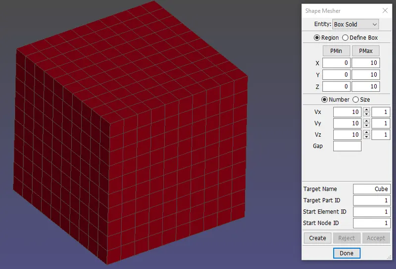
As per the given question, the cube with dimension 10mm*10mm*10mm with the element size as 1mm. The command used for the cube creation is Mesh module--->shape mesher--->box solid. is used.
Section creation:
Since the solid material is used we have to create a solid section and insert the given Element Formulations in the Keyword. The command used is
Model--->Keyword Manager--->Section--->Solid. The SECID and ELFORm tabs are filled.
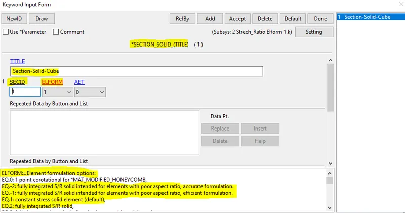
The highlighted ELFORM's 1,2,-1,-2 are used.
EQ 1: Constant stress solid element: default element type.
EQ -1: Fully integrated S/R solid intended for elements with poor aspect ratio, efficient formulation.
EQ 2: Fully integrated S/R solid, if element aspect ratios are poor, shear locking will lead to an excessively stiff response.
EQ -2: Fully integrated S/R solid intended for elements with poor aspect ratio, accurate formulation.
Creating Node-Set for Boundary conditions:
To simulate the real tensile test here we need to apply the boundary conditions on the cube. Here we need to consider the compression in other lateral directions of the material when one direction (ie, Y-direction) is pulled by a force. This we know by the generalized Hooke's Law.
So here we are applying the boundary constraint in such a way that the middle nodes along the vertical and horizontal direction will be constrained in their orthogonal directions. For this, we are creating two node sets in which one is formed with the middle nodes in the vertical direction and the other one is formed with the middle nodes along the horizontal direction. The command used to create SPC is Model--->Create entity--->Boundary--->SPC--->Create. Then the Constrained Nodeset is inserted through the command Model--->Create entity--->Set Data--->Set-Node--->Create.
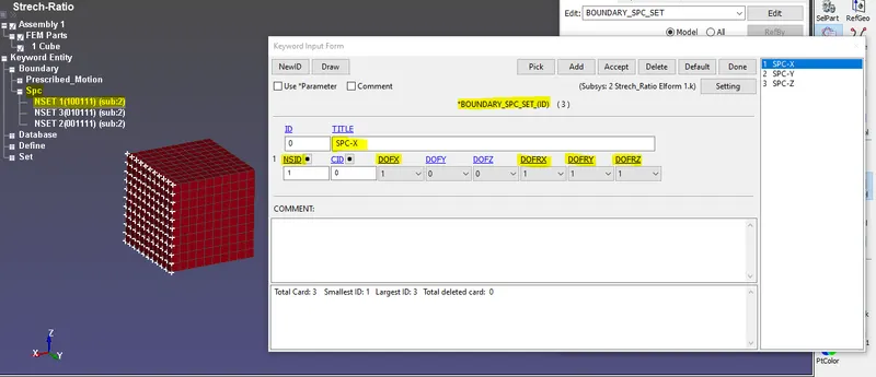
Figure 1- Showing Boundary SPC set constrained in the X-direction.
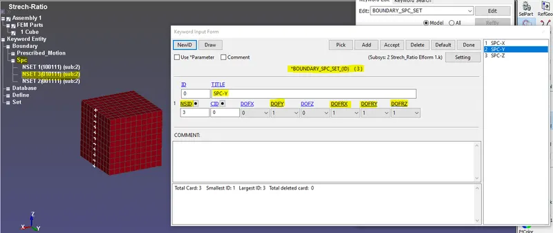
Figure 2- Showing Boundary SPC set constrained in the Y-direction.
In all SPC sets the rotational movements are strictly constrained since the system follows the tensile load.
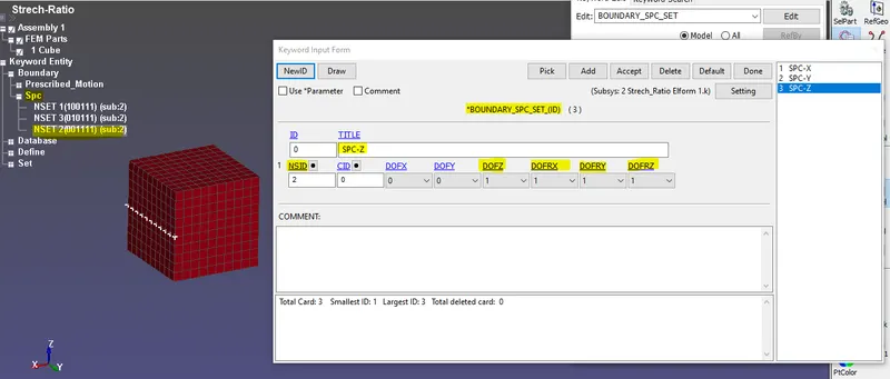
Figure 3- Showing Boundary SPC set constrained in the Z-direction.
Then we need to restrict those nodes along their orthogonal direction only using an SPC card. this will restrict those nodes in the two directions and then all the nodes in the constraining face are again selected as another node-set and set SPC in the Y direction so that the nodes will be restricted in the y-direction.
In all the keywords in SPC-Sets the DOF tabs are having Zero and One. Zero means not constrained and one means constrained in the respective directions.
Odgen material card:
The input .k file consists of a Material keyword card only. There is no change to be done to this card.
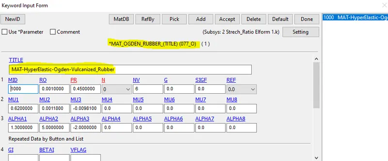
It is viewed through the command Model--->Keyword Manager--->MAT--->MAY_ODGEN_RUBBER. It is the HYPER-ELASTIC Material in nature.
Creating Boundary SPC-Set for Displacement:
The next step is to compare the graph which should have a stretch ratio of a minimum of 5 as a value, so we know the equation;
Stretch ratio = 1 + Engineering strain
Stretch ratio = 1 + dL/L
Let's substitute the stretch ratio as 5 and L = 10 mm
5 = 1+ dL/10
dL=40mm
The displacement value for the cube face is 40mm and here we need to input the load curve as a 50mm curve so in order to get the value way beyond the desired value.
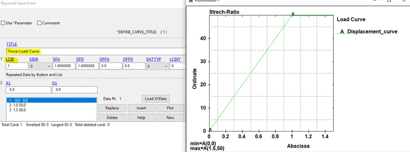
Then we will be defining a curve that ramps up from 0 to 50 in 1 millisecond. Then we define a node-set in the face in which we need to apply the displacement. And we will be defining this node-set in the Prescribed_motion_Set card. This will ensure that our model will behave as it is under the real tensile test.
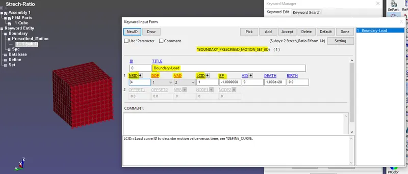
The command used for creating Nodeset is Create entity--->Set Data--->Set-Node--->Create. Then the Nodeset is inserted in the Boundary SPC set through the command
Model--->Create entity--->Boundary--->Prescribed Motion Set(BPM)--->Create.
The keyword cards like DOF are switched to 1-(X-directional translational). Then the VAD(Velocity, Acceleration, Displacement) is switched to 2-(Displacement only.) In the load curve, the displacement extends constantly after 1millisecond. This is done to avoid instabilities in the system during simulation.
IMPLICIT CARDS:
We need to convert the card for Implicit Analysis. So we need the implicit cards needed to be included in the deck. There are three important cards to be inserted to the system, they are
*Control_IMPLICIT_GENERAL,
*Control_IMPLICIT_AUTO,
*Control_IMPLICIT_SOLUTION.
The command used to create Implicit cards are from
Model--->Keyword Manager--->Control--->Implicit_Auto/General/Solution. are created.
*Control_IMPLICIT_GENERAL:
Here in IMPLICIT_GENERAL, we need to set the IMFLAG as 1 which tells the solver to switch to Implicit analysis mode.
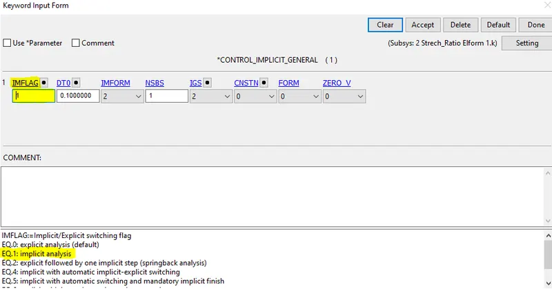
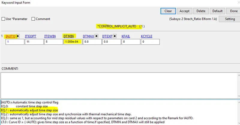
*Control_IMPLICIT_AUTO:
Then we need to create an IMPLICIT_AUTO Card. In this card, we need to set IAUTO as 1 which basically means the automatically adjusted time step size. Also in this card, we need to set DT_min. It means Minimum allowable time step size. The simulation stops with error termination if the time step falls below DTMIN.
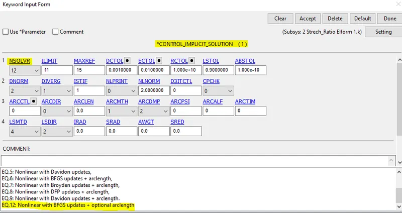
*Control_IMPLICIT_SOLUTION:
It is used for Non-Linear problems. Normally this solution card is used where the deformation is 100 to 500 times the original length value.
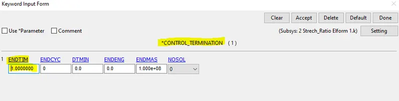
*Control_Termination card:
This card is inserted to terminate the simulation with the inputted stop time of the simulation. Based on this value only the time intervals are divided.
Similarly Database--->ASCII, Binary_d3plot and also select an element from the load face and set a card of History_Solid and we can get the values at the elout file for the data study like stress and strain of that defined element.
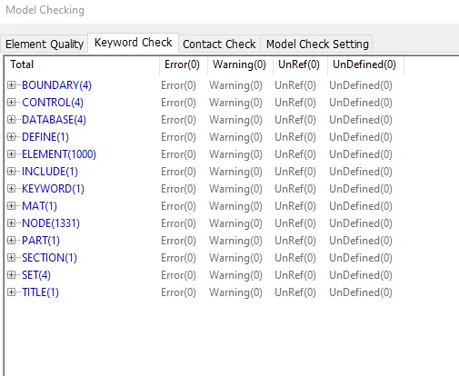
MODEL CHECKER:
It is opened through the command Model---> Model checks--->Keyword check.
SIMULATION:
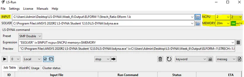
The model is saved in the local directory file and opened through the LS-RUn Manager. The deck will be given memory as 20M, if enough memory is not available, then the program will run out of core which will slow down the run. So we give 20M memory to ensure that doesn't happen. Then Set the number of CPU as 2, which will set the solver to solve the problem using a double-precision solver.
SIMULATION RESULTS:
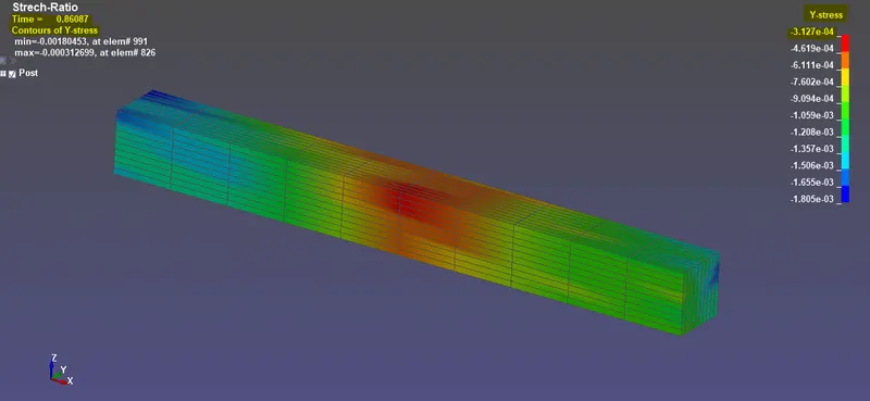
Stress in Global Y- direction:
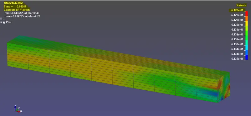
Strain in Global Y- direction:
CALCULATION OF ENGINEERING STRESS AND STRAIN:
To find the Engg. stress and strain from the True stress-strain data we have to copy and paste all the time step data and the true stress and strain value into Microsoft Excel. The value of Engineering stress and strain and the stretch ratio can be done with the following equation,
Engineering_strain = e^(True strain-1)
`epsilon_(E)=e^(epsilon_(t)-1)`
Stretch ratio = 1 + Engineering strain
Engineering stress (nominal stress) = True stress /Stretch ratio
The calculation for the ELFORM=1:
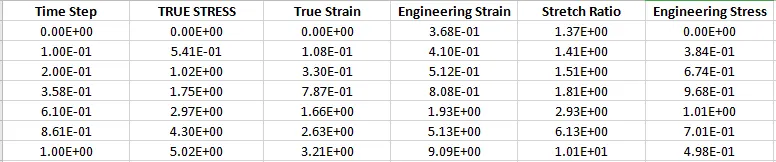
Similarly for other Element formulation calculations and simulations are done using the above steps. The simple way to edit all the (.K files) is to open in Notepad++ and edit the ELFORM division there and save it with the different file names in the local directory files.
Excel sheet Results:
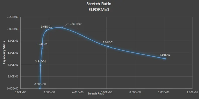
ELFORM=1:
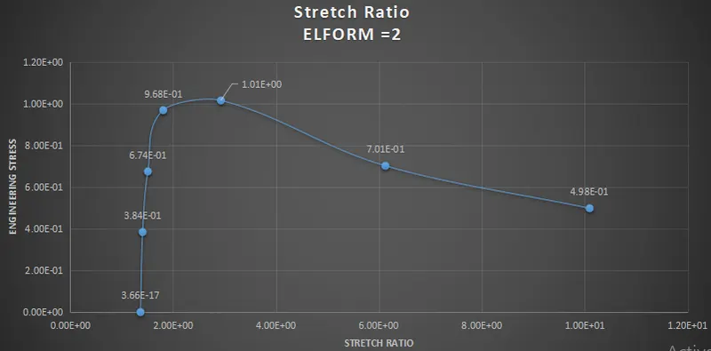
ELFORM=2:
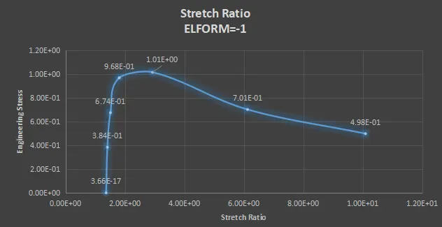
ELFORM= -1:
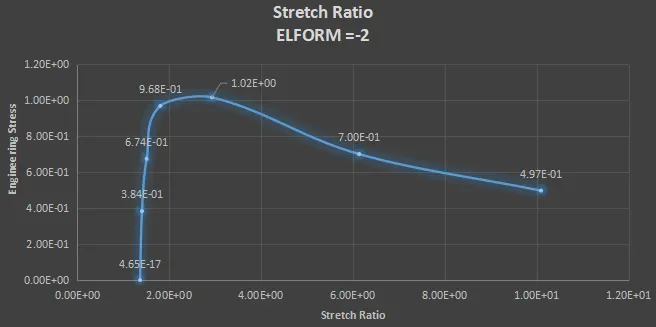
ELFORM=-2:
EXPLANATION:
The graph we got here for different ELFORM values is nearly the same. Different ELFORM serves different purposes. Since the problem is not so complex every element formulation succeeds in giving almost the same results. All the plots above show the maximum Engineering stress value of 1Mpa.
CONCLUSION:
The Cube of 10x10x10mm is created and the Section and material keyword cards are assigned. Boundary conditions are created for a simple tensile test. The Implicit control cards are used because it gives accurate solutions for simple components in Non-Linear analysis when compared to Explicit method.