Meshing on the Rear suspension Assembly using ANSA
ABSTRACT:
The objective of this challenge is to attempt a solid mesh on the given rear wheel suspension system and create suitable connections for the solid mesh. The CAD geometry is cleaned and meshed with the given quality criteria to achieve good mesh.
SUSPENSION SYSTEM:
The suspension system on a vehicle is between the frame and the road. The suspension system's primary function is to maximize the overall performance of a vehicle as it cruises down the road. The suspension system also helps to absorb bumps in the road and provide a safe and comfortable ride.
There are three main components present on all types suspension system, they are linkages, springs, shock absorbers. The conventional suspension came with both the shocks and the springs.
The given suspension system for the challenge is similar to independent suspension system(rear).
INDEPENDENT SUSPENSION SYSTEM:
The Independent suspension is any automobile suspension system that allows each wheel on the same axle to move vertically (i.e. reacting to a bump on the road) independently of the others.
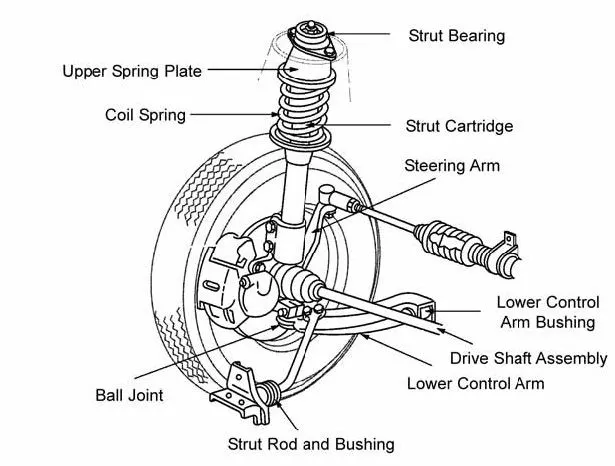
Many vehicles also have an independent rear suspension (IRS). IRS, as the name implies, has the rear wheels independently sprung.
PROCEDURE:
For the given component, there are both 1D, 2D, 3D meshing has to be done because it is having variable thickness all over the component. The following steps are followed to achieve the better mesh flow.
Geometry cleanup,
Midsurfacing 2D components,
Meshing 1D, 2D, 3D,
Quality checking,
Connections,
Reflecting Geoemtry.
GEOMETRY CLEANUP:
The component is opened using the command filemenu--->open. The component is opened from the local directory folder saved.
After the file is opened the geoemtry of the model is checked through the command
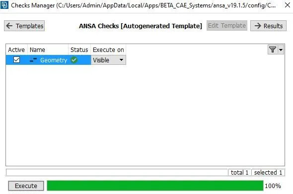
filemenu--->tools---> checks manager--->geometry.
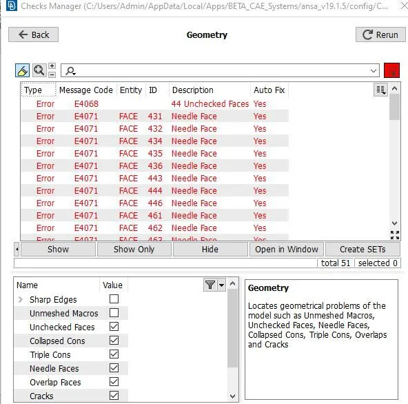
The checks manager used to say all the errors in the model and listed it in the window according to the list of input clenup parametres we given. The red coloured highlighted are the errors in the model and it is fixed by both the auto and manual way. After clearing the errors, the model is verified again for the no error confirmation.
Then the model is cleaned with the unwanted lines, points and removing the unwanted surfaces using the following tools.
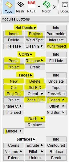
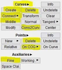
The above mentioned tools are used for the geoemetry cleanup process and the most frequently used tools are listed below,
topo--->hot points--->insert/project,
topo--->CONS--->paste/release/project,
topo--->Faces--->new/delete/cut/dach,
topo--->curves--->create/cons2curve/connect,
topo--->auxiliaries--->fine.
After the checks manager verification, the model is subjected to midsurfacing process.
EXTRACTING THE MIDSURFACE:
The giiven component is measured primarly to seperate the non uniform thickness and uniform thickness parts each other. The components with the thickness less than 5mm falls under the shell mesh and the rest comes under the solid tetra mesh. The command used for the measure is
filemenu--->utilities--->measure. The measured component is having thr thickness of 3mm. The uniform thickness components are offsetted manually through the command topo--->faces--->offset.
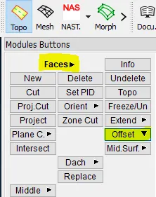
Before offsetting the thickness of the component is checked in various places and according to that data midsurface is done.
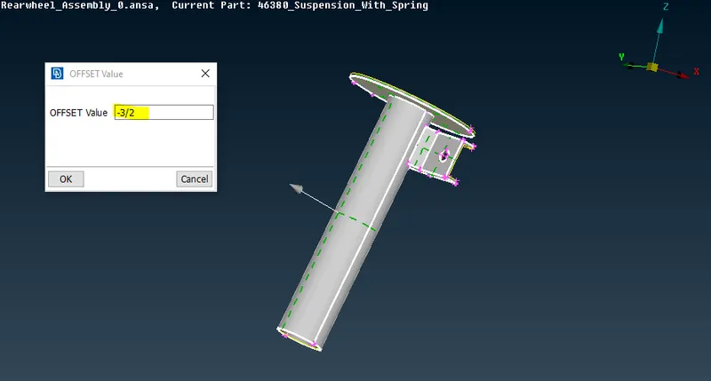
The input value is entered in the dialouge box and the new mid component is saved seperately in a new PID in the dataview tab.
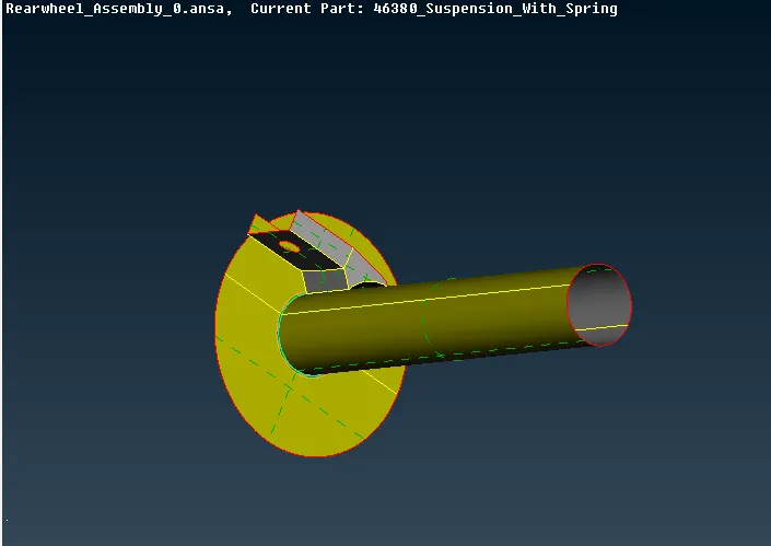
MESHING:
For the meshing process it is divided into three different meshing methods, they are
1D meshing,
2D meshing,
3D meshing.
1D meshing:
The spring component for the suspension system is designed with the 1D element.
Procedure for 1D meshing:
Generate a middle curve for the spring. By using the command topo--->curves--->middle.
Create a COG point for the curve to define the orientation. The command for the COG is
topo--->points--->on COG.
Select the CBAR element from the modules--->Nastran--->elements--->CBAR.
Then the spring is selected and then the orientation node is selected(COG point). The element size is inputted for the spring component as 3mm. The PBAR PID is created and the cross sectional area of the spring is entered. Then finally the 1D elemnts on the spring is created.
To see the representation of 1D bar elements as 3D (Solids) in menubar--->utilities--->
quality--->presentation parametres.
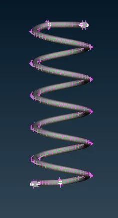 ---->
----> 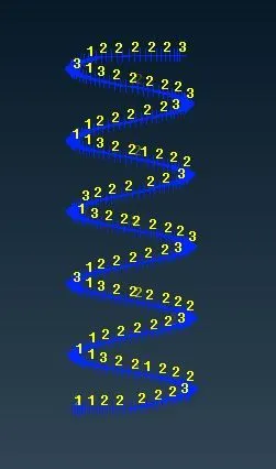
Before 1D meshing After 1D meshing
2D meshing:
For 2D meshing the element size is about 4mm and minimum, max length of the element are assigned in the quality criteria file. The mesh type is mixed in nature(tria and quad elements) are preferred.
After the middle surface extraction the geometry of the model is checked again for the error. Then the meshing is done through the command menubar--->mesh--->mesh generation--->best/spot mesh
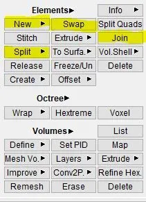
After the mesh was deployed to the surface, the element edit options like split, swap, join, paste, are used.
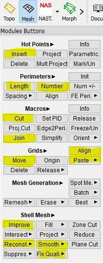
For whole modification of the mesh present in the surface mesh edit options like improve, reconstruct are used.
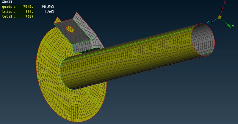
The top left corner of the figure shows the total no.of. quad and tria elemnts present in the component.
The goal is to create a mesh that accurately captures the input domain geometry, with high-quality, well-shaped, elements. The mesh should also be fine in areas that are important for the subsequent calculations. The 3 dimensional meshed elements are clasified into two different types, they are
Structured mesh (or) mapped mesh,
Unstructured mesh.
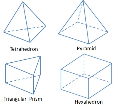
Structured mesh:
Structured grids are identified by regular connectivity. The possible element choices are quadrilateral in 2D and hexahedra in 3D.
This model is highly space efficient. Some other advantages of structured grid over unstructured are better convergence and higher resolution.
Unstructured mesh:
An unstructured grid is identified by irregular connectivity. It cannot easily be expressed as a two-dimensional or three-dimensional array in computer memory. This allows for any possible element that a solver might be able to use.
Compared to structured meshes, this model can be highly space inefficient since it calls for explicit storage of neighborhood relationships. These grids typically employ triangles in 2D and tetrahedral in 3D.
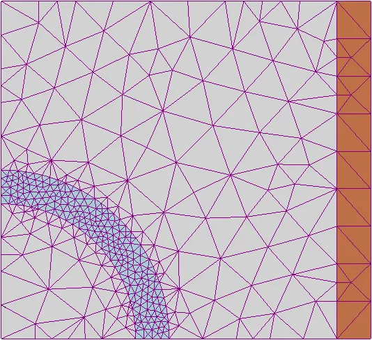
In this challenge , the followed mesh type is volume tetra meshing.
TETRA MESHING:
Tetrahedral is a four- nodded solid element which can be generated through the tria element by creating a volume and also through the existing volume of the geometry. These elements are used where the geometry has high thickness and complexity.
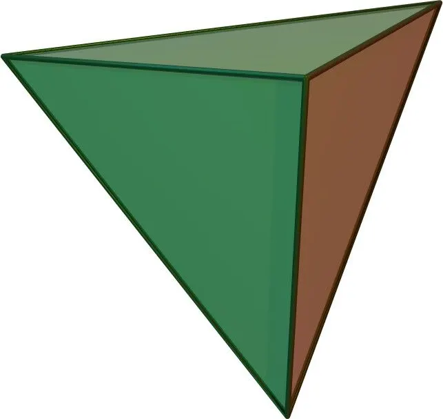
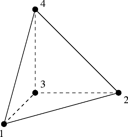
To achieve 3D meshing there is no need to take mid surfacing because the component has variable thickness in it.so, unable to take a midsurface and directly the 3d tetra mesh is done.
procedure for tetra meshing:
There are two steps followed for the solid meshing,they are 2D meshing, 3D meshing. The only difference in 2D mesh is the mesh type followed is tria only(ortho tria and tria).
Ortho tria vs tria elements:
The ortho tria elements are more accurate than the tria elements. The ortho tria are used in the curved regions and for the plane flat surfaces the tria elements are used.
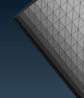
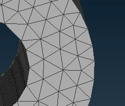
The 2D meshing is same as the above procedure. For solid meshing only two important criteria is followed for the shell mesh generation they are, minimum element length and maximum element length.
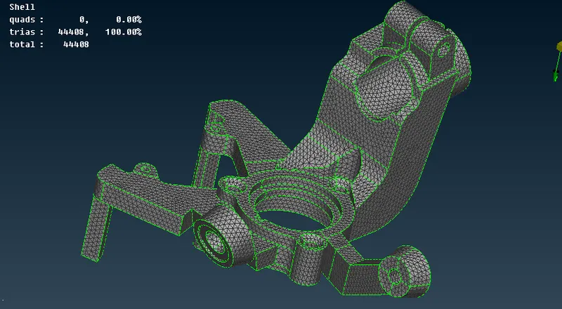
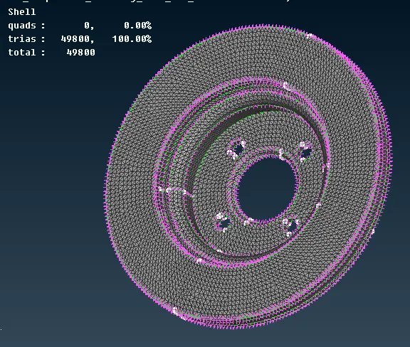
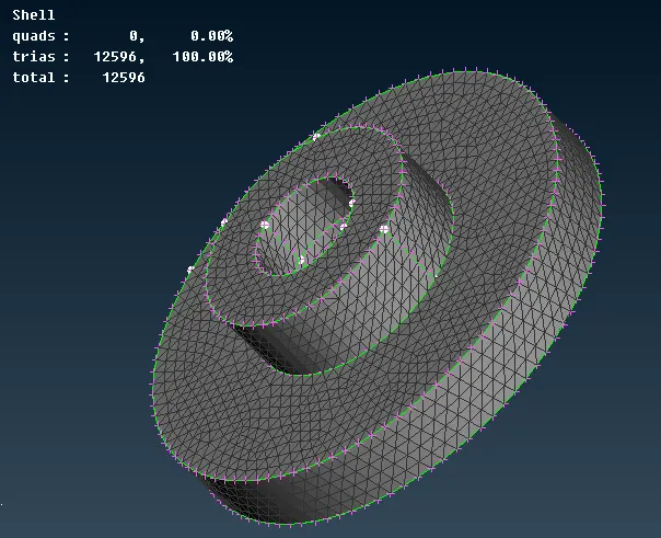
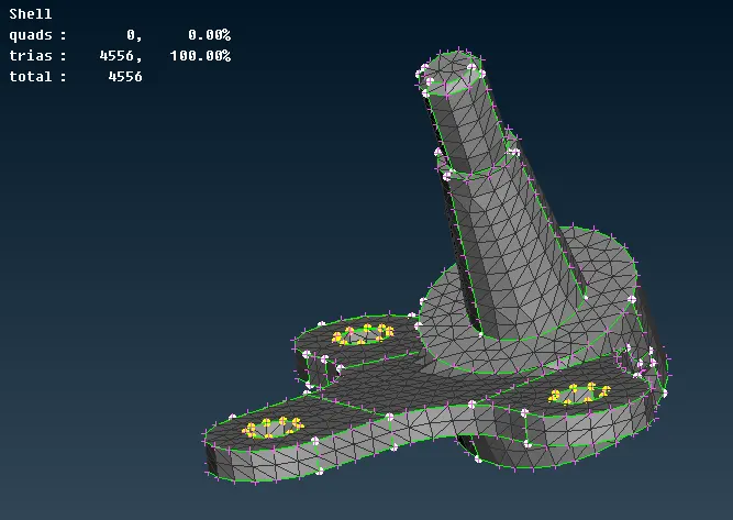
The above displayed figures are some of the shell meshed components. After shell meshing the tetra volume mesh is done through the command
menubar--->modules--->V-mesh--->volumes/unstructed mesh. are used.
Tetra rapid vs tetra fem:
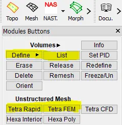
The main difference between Tetra Rapid and Tetra FEM is that in tetra fem mesh the volume mesh follows the certain steps of mesh which we have done on the surface and in tetra rapid mesh it does not follow it and to it rapidly.
After this the model is defined for the volume mesh and it is done from the volume mesh module--->volumes--->define--->manual.
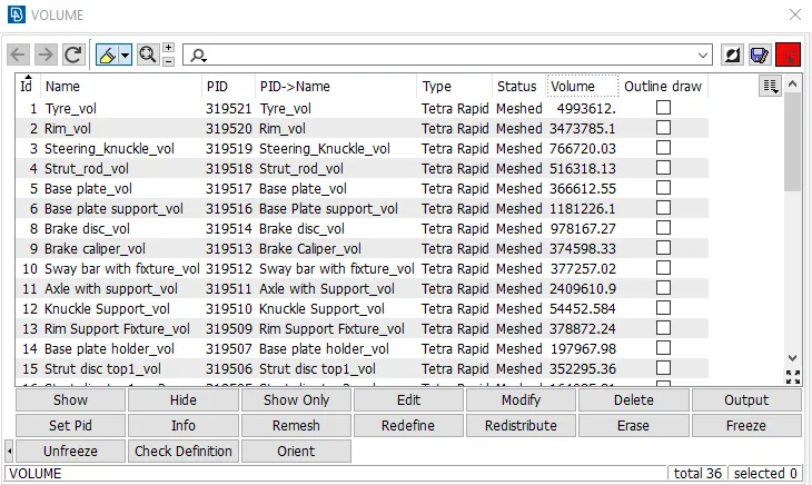
Then the volume is defines as an unmeshed property. Finally the tera mesh is deployed in the component through v-mesh module--->unstructured mesh--->tetra fem/tetra rapid option is used.
QUALITY CHECKING:
For quality checks the 1D elements are not included. Only 2D and 3D elements in the model is included. For 2D elements only minimum and maximum length of an element is considered. For 3D elements only tet collapse is taken for the consideration.
TET COLLAPSE:
3D tetra mesh created were checked for Tet collapse (defect generated when the height of tetrahedron 3D element is less than the target element length).
Tet collapse defects were cleared by re meshing the failed elements and changing the height of tetra element by translating nodes. The industries follow the default tet collpase value should be greater than 0.15.
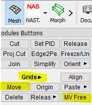
The tool used to clear the tet collapse is MV free. The command for this tool is
menubar--->modules--->mesh--->grids--->MV free.
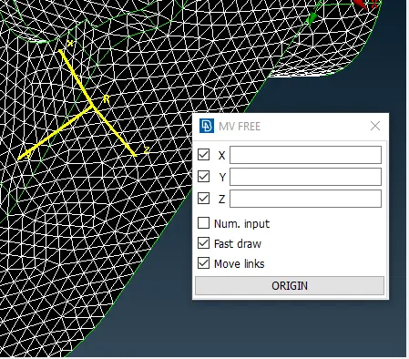
The direction where the node is moved is not constrained and the element is moved according to the axis selected. The move option is also used to move the node independently by the user.
CONNECTIONS:
The connections are executed for the model to ensure zero errors during the analysis part. If the connections are not deployed to the components then the model is diverged in the analysis part and becomes unstable. To avoid that connections like RBE2 elements are used on the model.
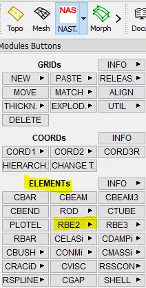
The command for RBE2 connection is menubar--->modules--->Nastran--->elements--->Rbe2.
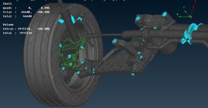
All the RBE2 elements are saved as PID in the database as RBE2.
REFLECTING THE GEOMETRY:
Finally the meshed geometry is reflected to the other side using the command
menubar--->utilities--->transform--->copy.
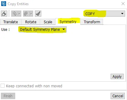
The default symmetry plane is used to reflect the model .This option just reflect the meshed model as it is the default global axis of the component orientation.
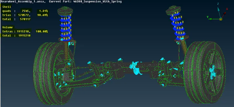
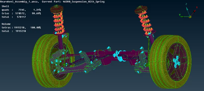
FINAL MESHED MODEL:
CONCLUSION:
The given component is geometry cleaned and then the whole component is seperated into small parts for easy access during the meshing. Then 1D, 2D, 3D meshing is done on the components respectively according to thier geometry nature. The quality for all themesh is checked and verified with zero errors in the meshed model. Finally the model is completed by giving suitable connections and the one side of geometry is refelected to other side using some tools in ANSA.