MESHING OF CAR HOOD IN HYPERMESH
OBJECTIVE:
The main objective of this model is to create a proper mesh for the given hood model. For that the model is cleaned and taken a middle surface.
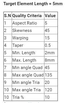
The flow of the mesh is taken into concern and the quality criteria is also assinged to the model.
QUALITY CRITERIA:
GIVEN MODEL:
For us the given model is Hood model.
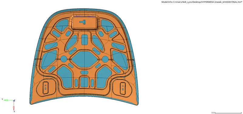
STEPS FOLLOWED:
Geometry cleanup,
Midsurfacing,
Meshing,
Quality checking,
Connectivity check.
Geometry cleanup:
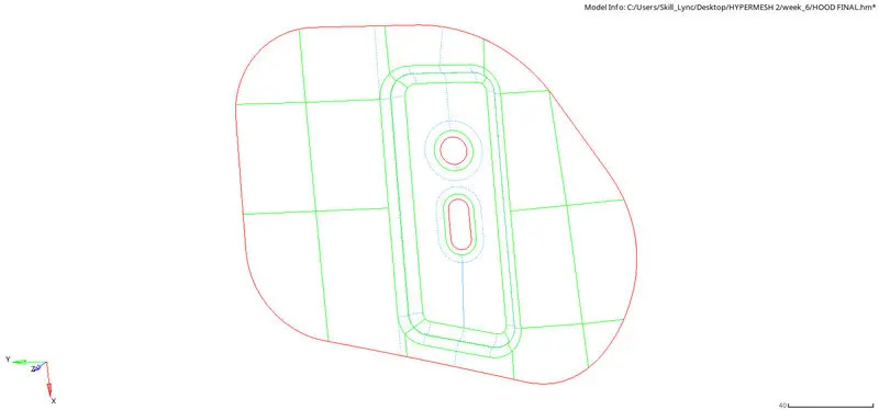
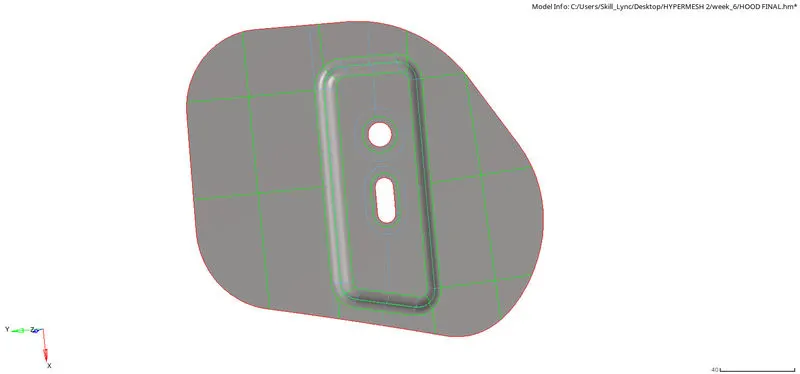
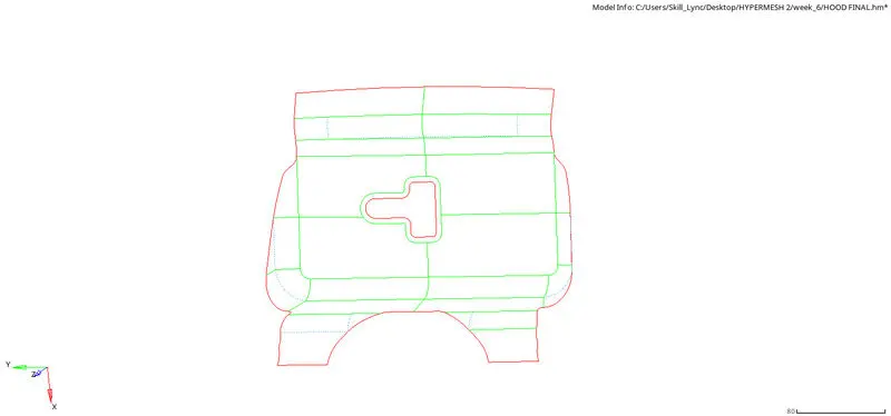
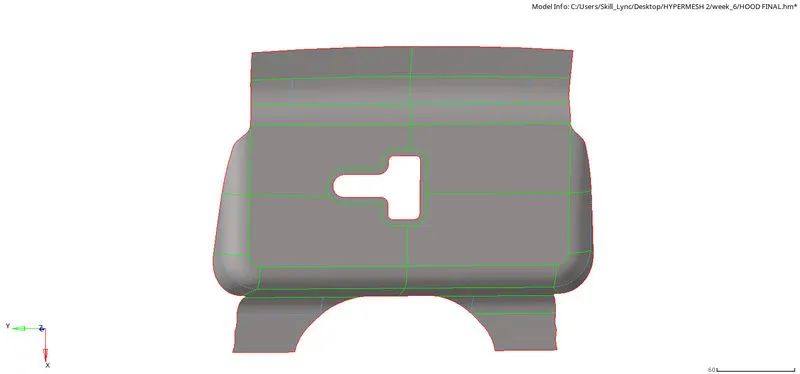
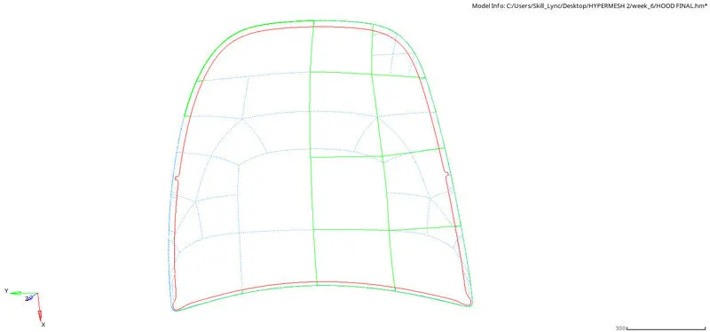
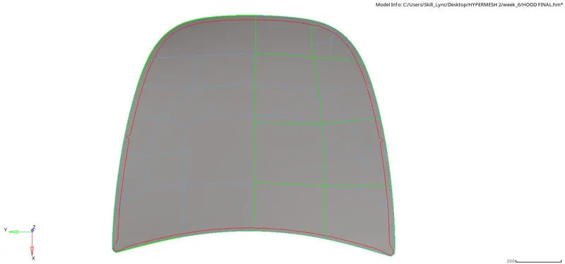
The process of cleaning the given CAD model. This includes deleting free edges, toggling the lines, hiding lines from the geometry etc are done.
It is done through the command geometry--->quickedit.

The commands like toggle edge, add/remove point, add point on line, replace point, split surf are used.
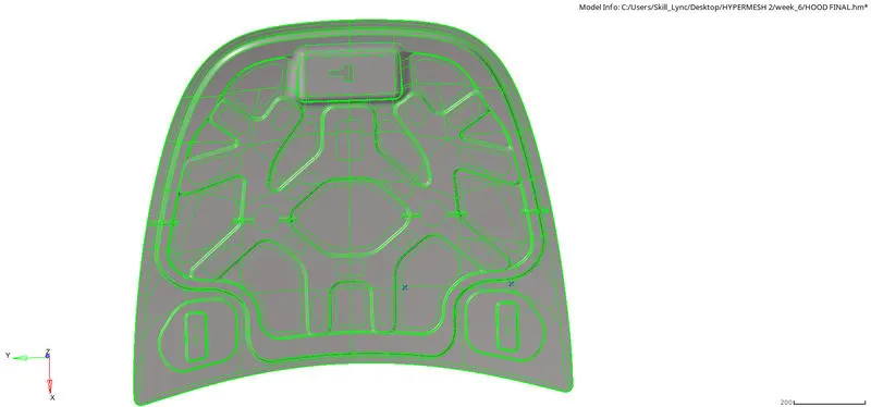
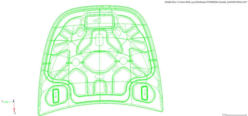
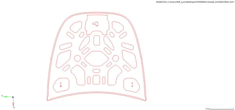
The green line shows us that the model is cleaned and there is no any geometrical errors present in the model. The wireframe and the shaded goemetry figures are shown above.
Midsurfacing:
The process used to create a surface in the middle of the model. The main significance of the midsurfacing is to do the 2d meshing. The 2D meshing is only suitable for the shell elements not for the solid elements. For that reason only the midsurfacing is done. To extract a midsurface the component should be a closed geometry.
The midsurfacing is done through the command geometry--->midsurface. There are some extraction options present in the midsurface tab. For an accurate midsurface the skin offset is used.
The components are seperated into different components and then done mid surfacing.
Hinge:
Latch:
Outer extract:
Inner extract:
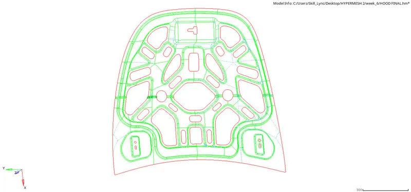
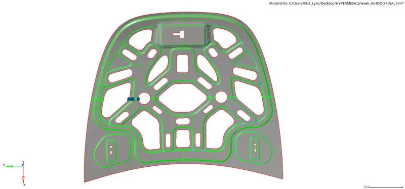
After doing midsurfacing the geometry is checked once again for the accuracy in the mesh.
Meshing:
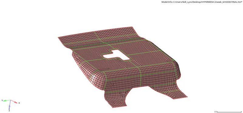
The meshing is done through the command 2D--->automesh. The element size is fixed as 5.

The mixed option is used because the system determines how the model is created and uses its own way to predict the type of mesh to be used.
Meshing is also done for each component seperately to reduce the risk of mshing errors. The model is soo large and it is not possible to mesh it in a single part. So it is partitioned into many identical parts and then meshed.
Latch:
Hinge:
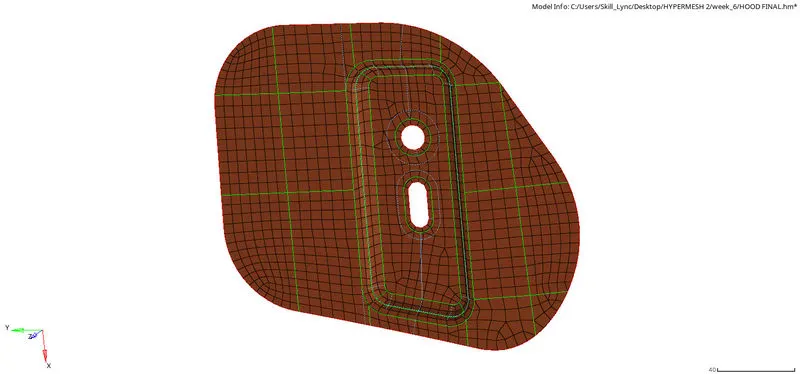
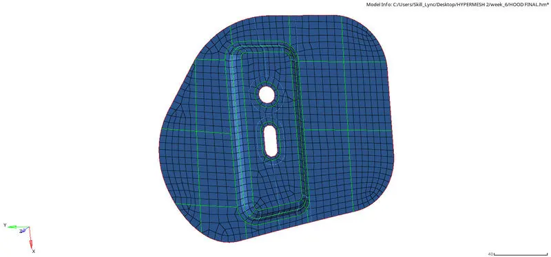
Here only one side of the hinge is meshed and for the other side the mesh is reflected using the reflect option.
Outer extract:
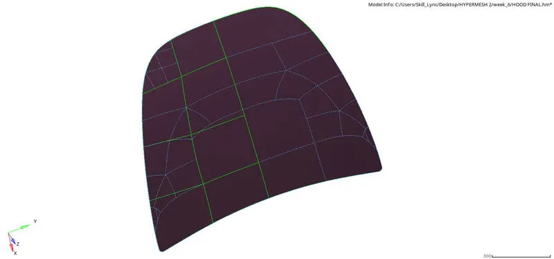
In this component meshing also the one side is refelected to the another side of the component. The green lines are used for the partition of the component into simple parts to reduce the risk of errors.
Inner extract:
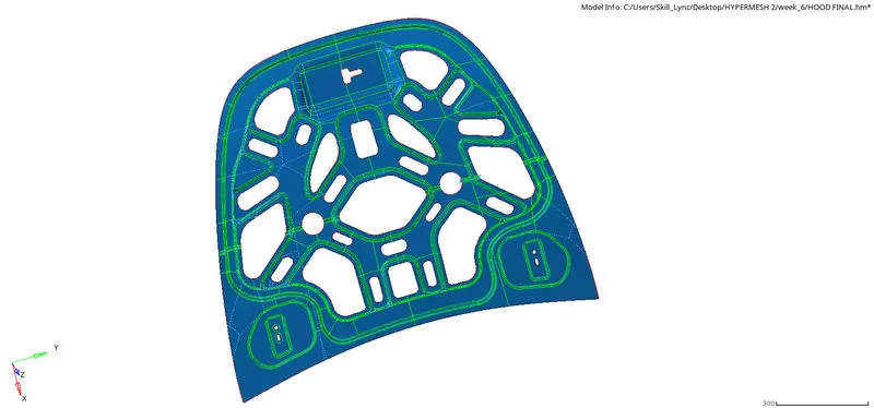
There are some cleaup tools used to make the mesh good and they are done through some editing commands in the hypermesh.

The highlighted options are used to edit the mesh and regulates the mesh flow.

To edit the particular single or group of elements and nodes the highlighted options are used.
Quality checking:
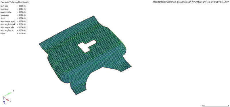
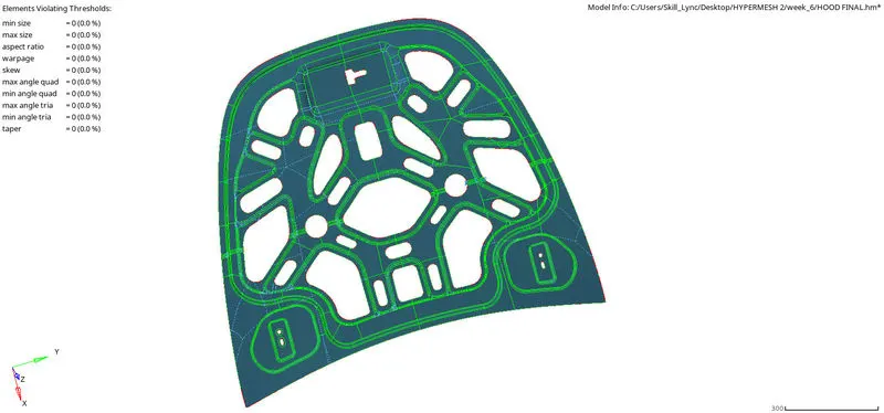
The important step that is followed to make tha mesh to see good is quality check. It is inputted to the system and the system meshes the model according to the criteria file loaded in the system.
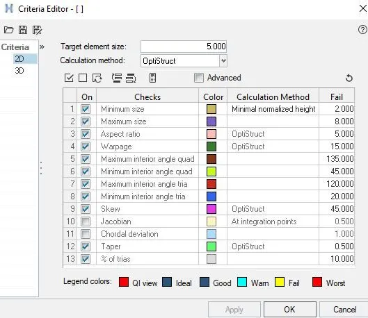
The ticked criteria is the most important quality to be seen in the model.
Hinge:
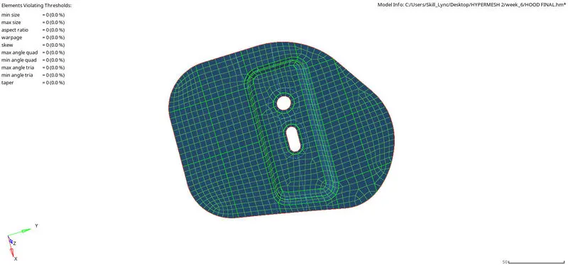
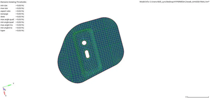
Latch:
Inner extract:
Outer extract:
Connectivity check:
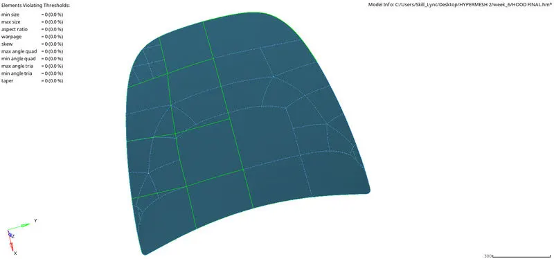
The connectivity is the last quality criteria to see. without this the connectivity the mesh of the elements can fail in the analysis and the model can diverge in the result.
FINAL MODEL:
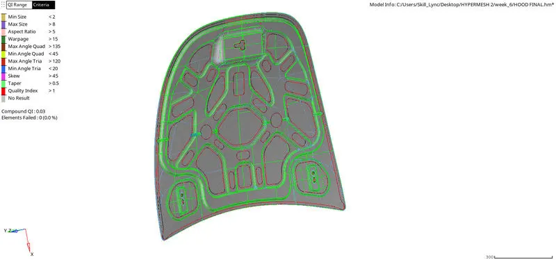
CONCLUSION:
Thus the given component is cleaned and taken midsurface and then the component is subjected to mesh. The quality of the mesh is good and there is no any error in the mesh. The connectivity of the elements are observed and the quality of the mesh is good.