DC Motor Control Using BJT H-bridge
BJT H-BRIDGE:
An H-bridge is an arrangement of transistors that allows a circuit full control over a standard electric DC motor. That is, an H-bridge allows a microcontroller, logic chip, or remote control to electronically command the motor to go forward, reverse, brake, and coast.
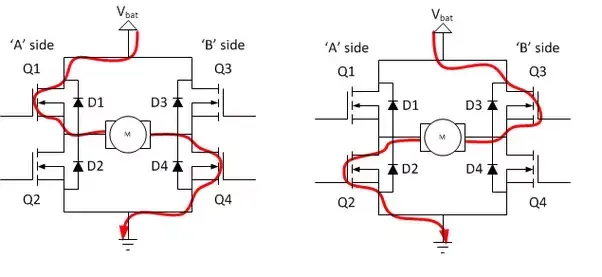
H-bridge is an electronic circuit that switches the polarity of a voltage applied to a load. These circuits are often used in robotics and other applications to allow DC motors to run forwards or backwards.
IGBT:
The insulated gate bipolar transistor (IGBT) is a semiconductor device with three terminals and is used mainly as an electronic switch. It is characterized by fast switching and high efficiency, which makes it a necessary component in modern appliances such as electric cars and variable frequency drives.
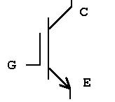
Its ability to turn on and off, rapidly, makes it applicable in amplifiers to process complex wave-patterns with pulse width modulation. It integrates an isolated gate using Field Effector Transistor to obtain a control input.
SIMULATION:
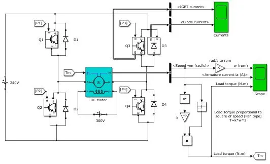
The Bipolar Junction Transistor (BJT) when used for power switching applications, operates as an IGBT. When it is conducting (BJT operating in the saturated region), a forward voltage Vf is developed between collector and emitter (in the range of 1 V). Therefore, the IGBT block can be used to model the BJT device.
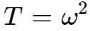
The IGBT block does not simulate the gate current controlling the BJT or IGBT. The switch is controlled by asignal. The DC motor uses the preset model (5 HP 24V 1750 rpm). It simulates a fan type load (where Load torque is proportional to square of speed).
The H-bridge consists of four BJT/Diode pairs (BJT simulated by IGBT models).
Two transistors are switched simultaneously as Q1 and Q4 or Q2 and Q3. When Q1 and Q4 are fired, a positive voltage is applied to the motor and motor runs in forward motion.
When Q2 and Q3 are fired, a negative voltage is applied to the motor runs in the reverse direction.
BJT H-BRIDGE CIRCUIT:
PULSE GENERATOR:
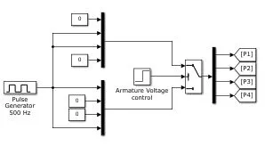
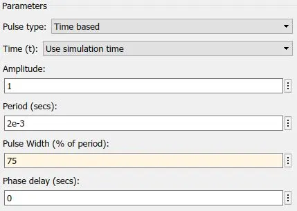
The armature mean voltage can be varied from 0 to 240 V when the duty cycle (specified in the Pulse Generator block) is varied from 0 to 100%.
AT 75% OF DUTY CYCLE:
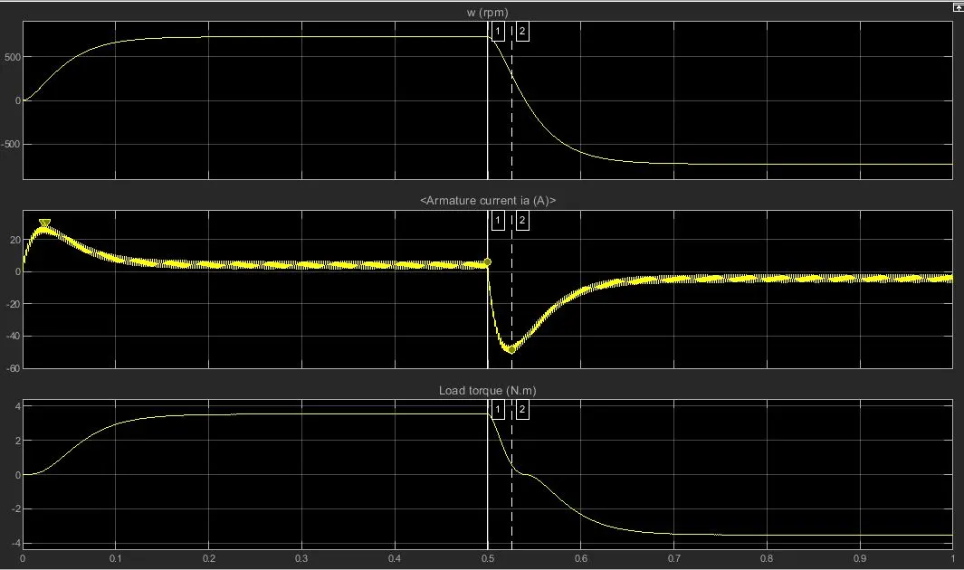
The motor starts in the positive direction with a duty cycle of 75% (mean DC voltage of 180V). At 0.5 sec the armature voltage is suddenly reversed and the motor runs in the negative direction.
AT 45% OF DUTY CYCLE:
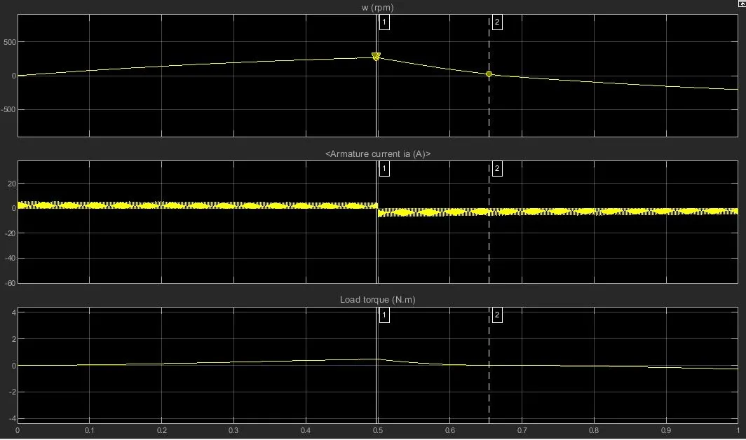
To rectify this the duty cycle is set between 40% to 50%. we can take 45% and the voltage drop is about to 108volts. After 0.5sec the motor gets reversed and the transition is smooth for the next half.
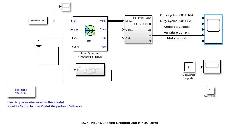
The Four-Quadrant Chopper DC Drive (DC7) block:
The 200 HP DC motor is separately excited with a constant 150 V DC field voltage source. The armature voltage is provided by an IGBT converter controlled by two PI regulators. The converter is fed by a 515 V DC bus obtained by rectification of a 380 V AC 50 Hz voltage source. In order to limit the DC bus voltage during dynamic braking mode, a braking chopper has been added between the diode rectifier and the DC7 block.
The first regulator is a speed regulator, followed by a current regulator. The speed regulator outputs the armature current reference (in p.u.) used by the current controller in order to obtain the electromagnetic torque needed to reach the desired speed. The speed reference change rate follows acceleration and deceleration ramps in order to avoid sudden reference changes that could cause armature over-current and destabilize the system.
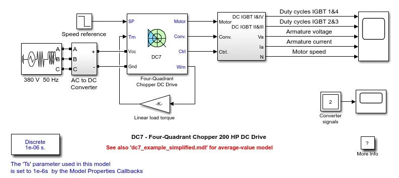
The current regulator controls the armature current by computing the appropriate duty ratios of the 5 kHz pulses of the four IGBT devices (Pulse Width Modulation). For proper system behaviour, the instantaneous pulse values of IGBT devices 1 and 4 are opposite to those of IGBT devices 2 and 3. This generates the average armature voltage needed to obtain the desired armature current. In order to limit the amplitude of the current oscillations, a smoothing inductance is placed in series with the armature circuit.
DIFFERENCES BETWEEN DC7 AND BJT H-BRIDGE:
H-BRIDGE:
It not used in controlling the motor drives while it is used in other industries.
The simulation time is less because it is continous in nature.
The polarity of the motor is changed by the use of the diodes.
The efficiency is low in this system.
DC7 BLOCK:
It is used to contol the motor and also used in the regerative braking of the motor.
The simulation is more than the H-bridge while it is discrete in nature.
To control the motor we need to cut the one signal and pass the other signal.
The efficiency is high for this block.
EV MODELLING USING DC7 BLOCK:
To create a new model the blocks are changed in the system. they are listed below;
Load torque,
Power supply,
Drive cycle.
LOAD TORQUE INPUT:
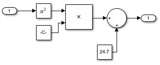
For the torque input the 'speed torque characteristics' equation is used.

SUBSYSTEM FOR THE EQUATION:
POWER SUPPLY:
The power supply used here is DC VOLTAGE SOURCE.
The voltage is set at 100v.
DRIVE CYCLE:
The drive cycle used here is imported from the excel sheet where the different speed values are entered at the same constant interval of the time.
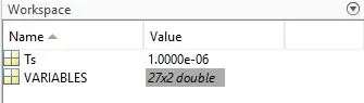
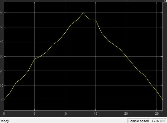
EXCEL SHEET VARIABLES:
https://s.docworkspace.com/d/AOUIRhWqpeIs4cHLm9edFA
DC7 MODEL:
SIMULATION:
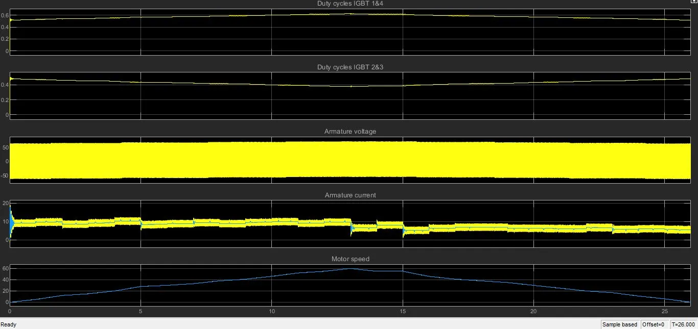
The drive cycle with speed and time is simualted with the 100v DC supply through the load torque unit.
The motor speed,armature current,armature volage are simulated with the duty cycle in the four quardrent chopper device.
At a certain time the armature current gets reversed and the braking torque is produced, this increases the DC voltage.
The motor speed is matched too the system.
Thus the EV model is created using the four quadrant DC Drive.