MESHING of SIDE DOOR INNER PANEL USING HYPERMESH.
ABSTRACT:
The given side door model is taken a midurface and then the geometry of the midsurface component is cleaned for doing the mesh. Then the meshed component is checked for the quality parametres.
MESHING:
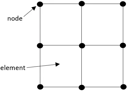
The meshing is the part of the FINITE ELEMENT METHOD and it refers mostly to complex mathematical procedures used in solver. It deals with the theory manual, lots of equations and mathematics.FINITE ELEMENT ANALYSIS (FEA) is usually used in the context of applying FEM to solve real engineering problems.
PURPOSE OF MESHING:
Meshing is an integral part of the engineering simulation process where complex geometries are divided into simple finite elements that can be used as discrete local approximations of the larger domain. The mesh influences the accuracy, convergence and speed of the simulation.
The FEM consists of three phases ,they are
Preprocessing,
Analysis,
Postprocessing.
FINITE ELEMENT METHOD:
The Finite Element Method (FEM) is a widely used method for numerically solving differential equations arising in Engineering modelling. It deals in the fields of structural analysis, heat transfer,fluid flow, mass transport. The FEM is a particular numerical method for solving partial differential equations in two or three space variables. To solve a problem, the FEM divides a large system into smaller, simpler parts that are called finite elements.
This is achieved by a discretization of the model which is implemented by the construction of a mesh of the object. The finite element method formulation of a boundary value problem finally results in a system of algebraic equations. The simple equations that model these finite elements are then assembled into a larger system of equations that models the entire problem.
STEPS INVOLVED IN FEM:
The Finite Element Method is a numerical procedure for obtaining solutions to boundary-value problems. The principle of the method is to replace an entire continuous domain by a number of subdomains in which the unknown function is represented by simple interpolation functions with unknown coefficients. Thus, the original boundary-value problem with an infinite number of degrees of freedom is converted into a problem with a Finite number of degrees of freedom. A Finite Element Analysis of a boundary-value problem should include the following basic steps.
Discretization or subdivision of the domain.
Selection of the interpolation functions.
Formulation of the system of equations.
Solution of the system of equations.
DISCRETIZATION OF THE DOMAIN:
The process of dividing the body into an equivalent number of finite elements associated with nodes is called as discretization of an element in finite element analysis. Each element is associated with the actual physical behavior of the body.
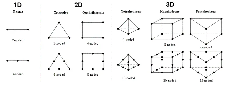
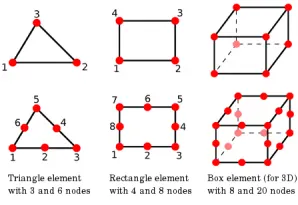
For a 1D domain which is actually a straight of curved line, the elements are often short line segments interconnected to form the original line.
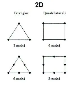
For a 2D domain, the elements are usually small triangles(tria elements) and rectangles(quad elements). The quad elements are best suited for discretizing rectangular regions, while the tria elemets ones can be used for irregular regions.
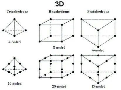
For a 3D domain, the domain may be subdivided into tetrahedra, hexa elements .
The subdomains are usually referred to as the elements.
SELECTION OF THE INTERPOLATION FUNCTIONS:
In FEA we discretize the solution region into finite elements. To conduct the analysis we assume a displacement model to approximately indicate the variations of the displacement within the element. The polynomial chosen to interpolate the field variables over the element are called shape functions Denoted by[N], they establish the relationship between the displacement at any point in the element with the model displacement of the element.
There are three types of interpolation methods used in FEM, they are
Polynomial Interpolation method,
Linear interpolation method,
Piecewise Constant Interpolation method.
The most common inetrpolation method used for the FEM is Polynomial Interpolation method it is easy to integrate/differentiate the formulation and computation of the finite element equations are easy. The accuracy of the results can be improved by increasing the order of the polynomial.
FORMULATION OF SYSTEM OF EQUATIONS:
When the discretization is done the system formulates some differential equations to the FE model. Then the interpolation process takes places in the nodal points as the shape function is described to the model. All the interpolated fuctions are converged to find the mixima and the minimum points from the set of equations.
After the convergence done the model is subjected to an external force and the solution for the equations are obtained.
TYPES OF ELEMENTS:
There are three types of elements present in the FE modelling, they are
1D elements,
2D elements,
3D elements.
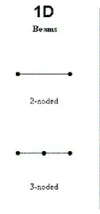
1D elements: 1D element is used for long and slender structure.
2D elements: They are used for sheet metal or shell like structures.
3D elements: They are used for structure with complex geometry which cannot be simplified for analysis.
OPTISTRUCT VS RADIOSS:
OptiStruct is used for modern structural analysis solver for linear and non-linear structural problems under both static and dynamic loadings.
RADIOSS is used for structural analysis solver for highly non-linear problems under dynamic loadings. It is highly differentiated for Scalability, Quality and Robustness, and consists of features for multi-physics simulation and advanced materials such as composites.
PROCEDURE:
The given side door panel is imported to the Optistruct solver and the geometry is cleaned to apply middle surface of the component. Then the new mid surface is topology cleaned and subjected to mesh. The meshing tools are used on the model to bring the mesh better and the quality of the model is ensured. The quality parametres are inputted to the Preprocessing deck and our aim is to make mesh in good quality.
After the quality checking is done ,the thickness is assigned to the component. Though it got some variable thickness in the ribs region, different thickness values are assinged to the model.
IMPORTING THE MODEL:
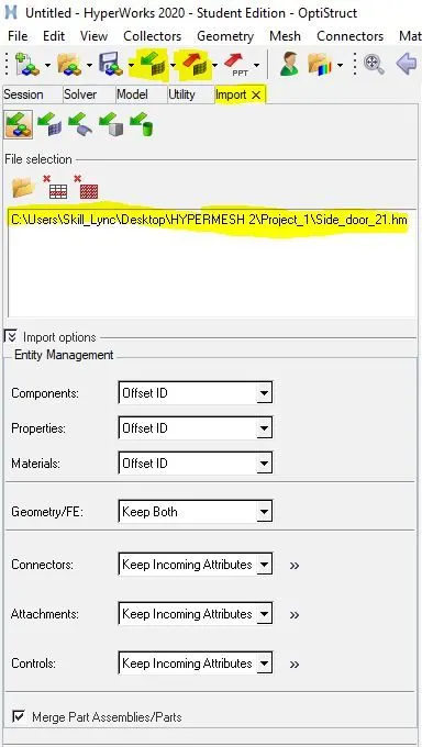
The model is imported to the Hypermesh window through the import option in the menu bar. The input mode3l is in the .hm format and the model import option is used.
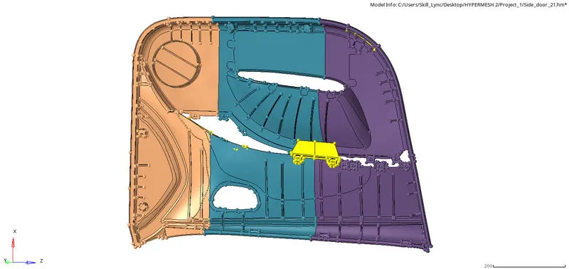
The imported model is viewed using the model view view bar.
GEOMETRY CLEANUP:
The side door panel is a plastic component and it has a variable thickess in it. So the model is splitted into different parts and organised into new components seperately. then the model is cleaned. The cleaning process consists of
closing the holes below 3mm,
toggeling the unwanted lines in the surfaces,
defeaturing the small dia fillet areas,
splitting the surfaces into parts,
filling the empty surfaces,
add/remove the points in the lines,
delete the unwanted surfaces.
There are many useful tools present in the Hpermesh to aviod errors in the model during meshing. The main tool we used in the model is Geometry--->quick edit. The shortcut used for the quick edit tab is F11 key from the keyboard.

Split surf-node:
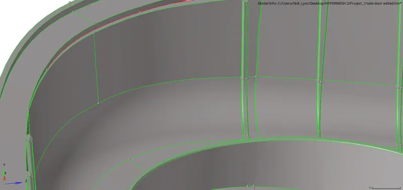
The trim lines in the curved surface in not fully connected to the surfaces and this makes some errors while meshing. To avoid this type of errors split surf-node/split surf-line potion is used. The first option is used to connect two nodes and the second option is used to connect straight line selected.
Toggle edges:
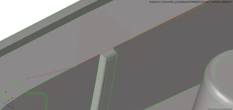
The red line indicates that the line is not shared with the adjacent line and it is called as free edges. To avoid this toggle edge options is used. After togglling the lines the red line is changed to green shared line.
Filler surf:
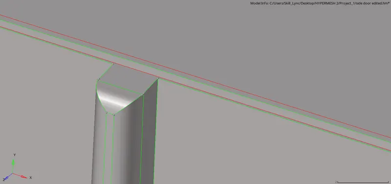
By using the filler surf option the surface is filled. There is also another option used to create surfaces in the missing surface
Geometry--->surfaces, option is used.
Add/remove points:
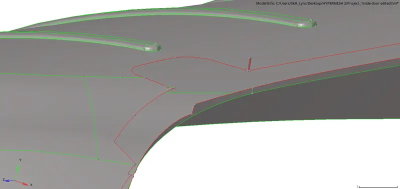
In the fee edge there should be no extra points present it will affect the mesh quality. To remove this unwanted points in the lines, the add/remove points is used.
Project point:
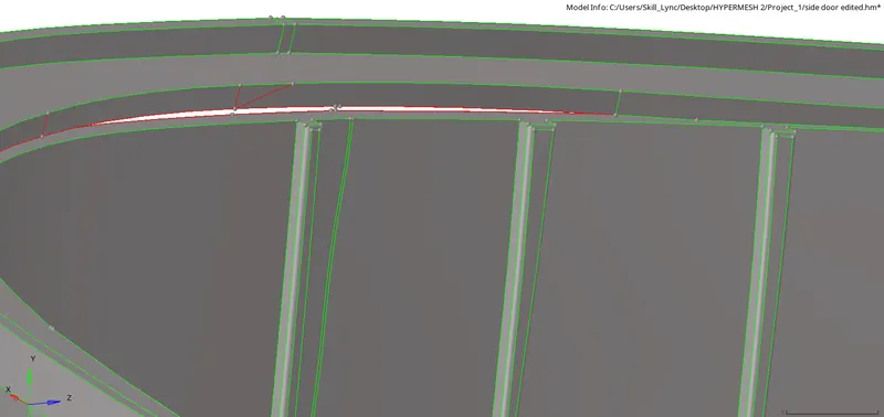
This option is used for pasting two nodes present in two different lines.
MIDDLE SURFACING:
After the topology cleanup is done the mid surfacing process is started. There are two different methods used for mid surfacing, they are manual midsurfacing, auto midsurfacing. In this challenge I took manual midsurfacing because the model is not a closed volume and having so many variable thickness areas.
The command used to manul midsurfacing(offsetting) is done through Geometry--->surface edit--->offset. The shortcut used for surface edit tab is Shift+F9 from the keyboard.

The surface that is to offsetted is selected and the offset value is given. The parent surface geometry is duplicated and then offsetted. The base surface is having the uniform thickness and it is offsetted in one shot.
DEFEATURING THE SURFACES:
The main challenge is taking mid surface for the rib areas. For that the ribs are defeatured and then midsurface is taken. The manual midsurfacing is more approachable than the automid option. The command for defeaturing is Geom--->defeature--->select the surfaces and then the tolerance value is given.

The fillet areas in the ribs less than the value given are removed and made as flat surface and radius more than the given value are ignored.
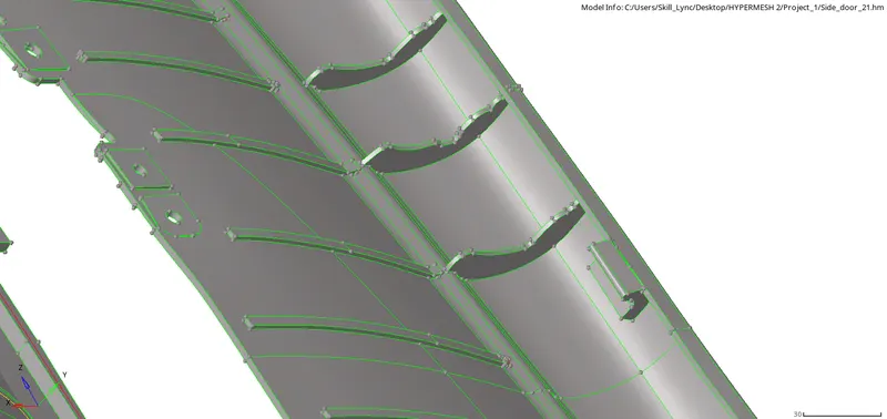
After the ribs are defeatured the midsurfacing for the ribs are taken using two different methods
Geom--->midsurface--->final edit tools,
Geom--->lines--->midline option.
Attaching the ribs to the surface:
The purpose of ribs in the door panel is to prevent the door panel from bending or avoid breaking conditions during some imapcts. For that the rib is attached to the surfaces after the midsurface for various surfaces and the ribs are done. This is done through the command
geom--->surface edit--->extend (or) trim with surfs/plane option

The lines that is to be extended and the target surface is given to the system then the system automatically attach two surfaces together.

The self interacting(contactless) surfaces are trimmed using this option. After the lines are trimmed with the surface it is appeared in yellow line(sharing three surfaces).
Other tools used:
There are other tools used for the small works in the model, they are distance, temp nodes, nodes, line edit options.
FINAL MIDSURFACE:
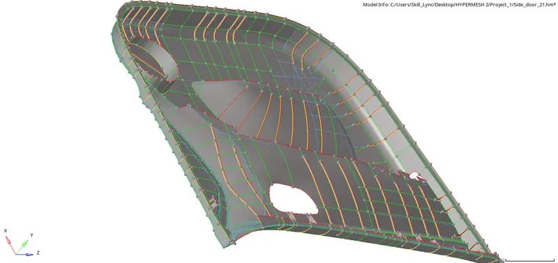
MESHING:
For meshing the target element length is 4mm, minimum length is 2mm, maximum length is 6mm. The quality criteriafile is inputted to the model. The command used for the automesh is 2D--->automesh. The shortcut used for the automeshing is F12.
 The meshing is not done for the whole component in a single shot. Rather than the surfaces are splitted with the lines and seperated into small surfaces. Then the small surfaces are meshed one by one. This makes the mesh flow even in all places.

The density of the mesh is very important. when it is subjected for some external force or shock wave if the mesh is so denser the time step may affected. So the mesh density should be so finer in way to avoid some errors. The density option in automesh option used for adjusting the density of the mesh.

This option is used to modify the style of the mesh and also modify the mesh in the complex areas.
TOOLS USED TO EDIT THE MESH:
To make the mesh better some tools are used they are smoothing, rebuild mesh, quality index, element cleanup, replace, project, edit element, translate, quick edit, mask are used.
Smoothing:
The process of aligning the set of elements in a proper flow. the command used for smoothing is 2D--->smoothing. The shortcut key for smoothing is Shift+F12.
Rebuild mesh:
This option is associated with the quality criteria file and this option automatically modifies the mesh with respect to the surface. This option is only used in the complex regions that the normal automesh is not working properly. The command used for rebuild mesh is 2D--->rebuild mesh.

Quality index:
This tab is used for editing a elements quality parametres like min length, max length, trai elements etc.

Replace panel: Use the Replace panel to relocate one node to the position of another or manually equivalence two nodes. The shortcut used for the replace option is F3.
Project panel: Use the Project panel to project element or nodes to a plane, vector, surface, or line. The shortcut used for the project option is shift+F7.
Node edit panel: Use the Node Edit panel to associate nodes to a point, line, or surface/solid face, move nodes along a surface, place a node at a point on a surface, remap a list of nodes to a line, project nodes to an imaginary line passing through two nodes. The shortcut key used for this option is F7.
Edit element panel: Use the Edit Element panel to create, combine, split, or modify elements. The shortcut used for the edit elemen
option is F6.
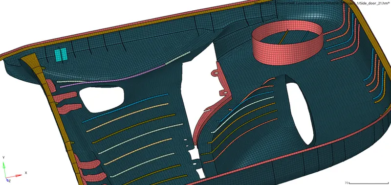
FINAL MESHED MODEL:
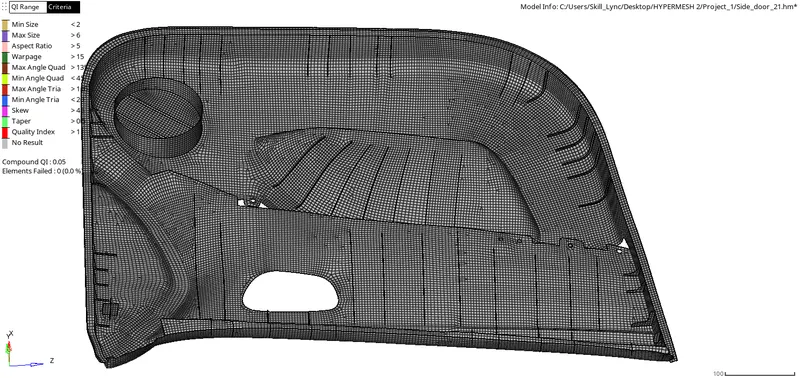
QUALITY CHECKING:
The quality checking is the important feature to be checked before finishing the model. The quality parametres are inputted to the model through menu bar--->preferences--->criteria file settings. Then each and every failed elements are solved using some tools in the Hypermesh tools panel.
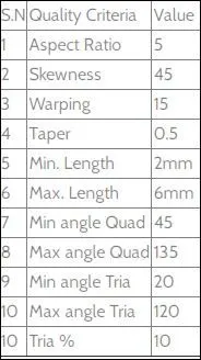
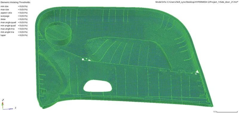



All the elements in the model's mesh is solved and no element is failed for the quality. The percentage of trai elements is about 1.4%(536nos) out of 10%.
CONNECTIVITY CHECKING:
The next quality checking step is checking for connectivity between the elements. When the elements are subjected to a external force without connectivity the model will fail in the analysis part. so it is important to ensure the connectivity between all the elements present in the model.
The command used for the connectivity option is Tools--->edges. The shortcut key used for edges panel is Shift+F3.
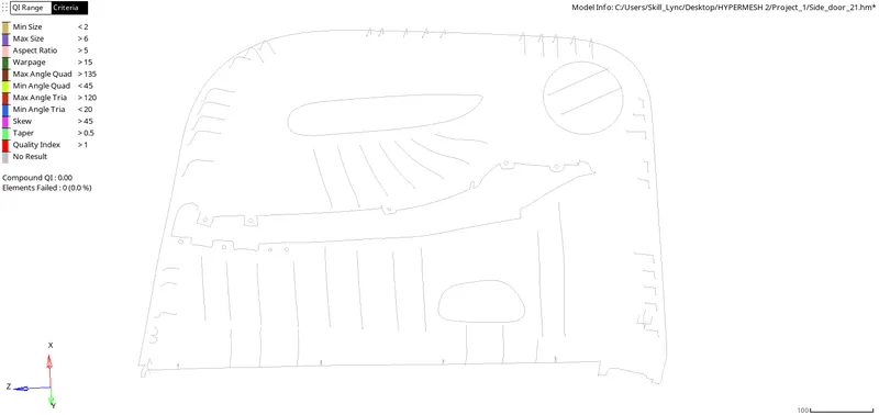
Then finally check if there is any duplicate elements present in the meshed model. It is checked from the check elements panel. The shortcut used for check elements panel is F10.
ASSIGNING THICKNESS:
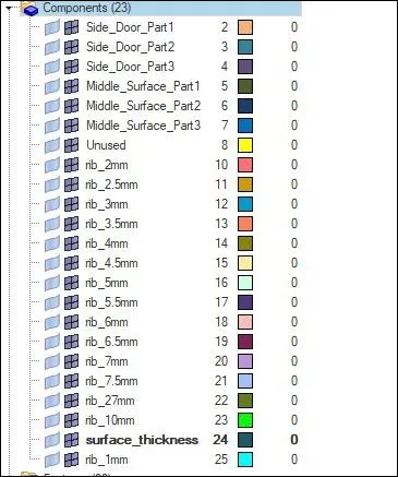
Finally the meshed model is assigned a thickness value. The thickness value varies from 2mm to 10mm in the model. So each and every surfaces and part of the meshed model is organised to various components created. The mesh is organised through the command
Tools--->organise elements.
CONCLUSION:
The given side door panel is maually taken midsurface and then the geometry of the newly created midsurface is cleaned. Then the mesh is created on the surface and subjected to the quality checking process and passed the checcking process. Finally the thickness is assigned to the model with variable thickness to each and every component. As when we used to perform meshing in the complex or simple regions the main aspect we have to see is the geometry capturing and the quality of the mesh. If this two parametres are perfectly balanced in the mesh makes the model to pass in analysis part. So the process of meshing the complex plastic component is learned with this challenge.