Assignment 5
BUMPER ASSEMBLY:
CREATING A MESH FOR BUMPER ASSEMBLY:
The bumper assembly is opened into the Hyper mesh window and the geomerty cleanup is done.
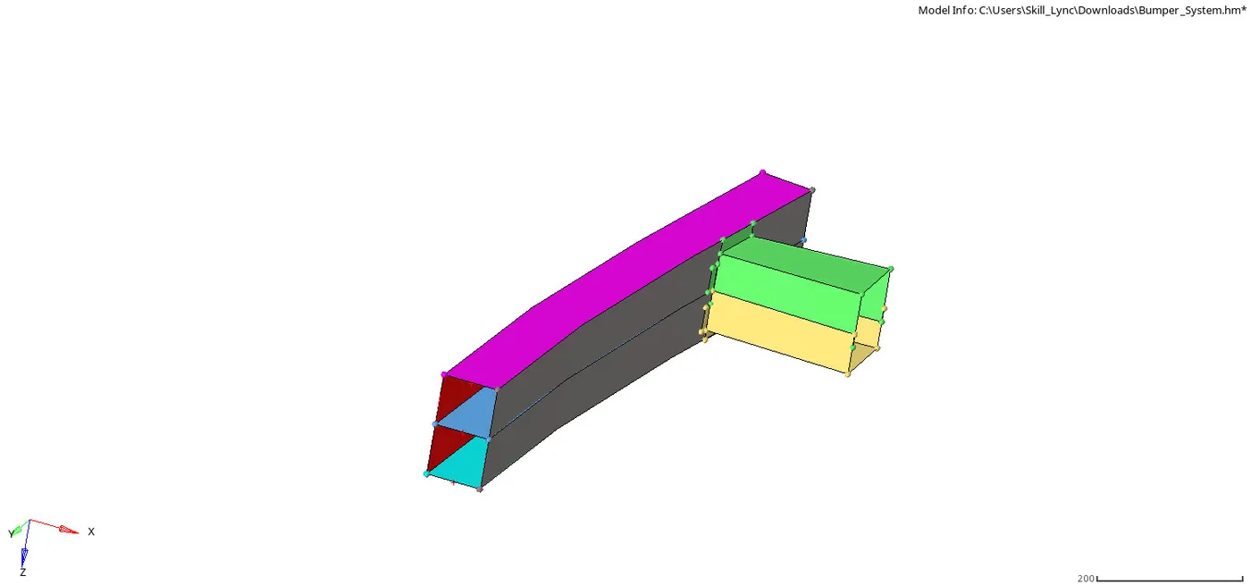
Then the assembly is meshed with the mesh size of 6mm as given in the question.
It is done through 2D--->Automesh--->mesh size--->mesh.
Then the tria elements are dismissed from the bumper beam and the crash box.
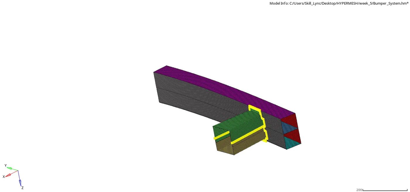
The connecting points are given to the crash box and the beam using a seam weld.
That is done through 2D--->connectors--->seam--->create--->spacing--->selecting lines and components--->create.
CRASH TUBE:
The most important phenomenon in a crush or crash situation is to absorb the kinetic energy. Crash tubes are designed for that purpose and are used in many practical situations. They have the ability to absorb and convert large amounts of kinetic energy into plastic strain energy under severe loading conditions.
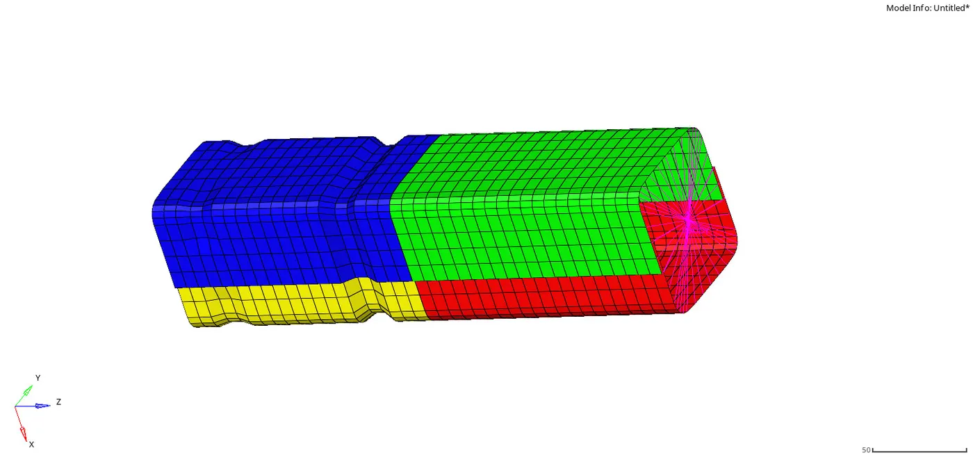
In the challenge there are 6 cases are asked to solve and compare the results of the crash with each other.
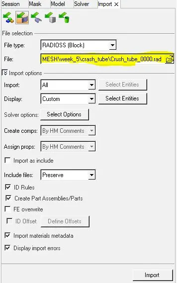
For all the cases the crash_tube_0000.rad file is imported.
Case1:Run the crash tube model as it is.
Case2:Change the Inacti=6 and run.
Case3:Create the type 11 contact and run.
Case4:Remove both notches and remove boundary condition on rigid body node then run.
Case5:Create a new notch in the middle ,select the whole section and run.
Case6:Create a new notch with nodes only from opposing 2 faces and run.
TH/PART:
TH means Time History for the parts. The variation in the simulation results are plotted to get the changes according to the input values given to the system.
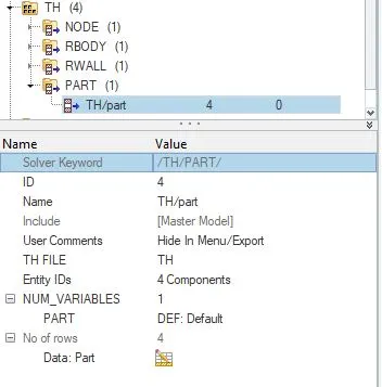
There ate four parts are described in the system. To get a detailed results the TH/PART is created using solver--->TH--->create--->part--->assign comps.
This is common for all the cases.
CONTACT INRTERFACE:
Interfaces are defined as the contact between two components when they are subjected to some external push(rigid body). This makes the model to deform and the nodes that are internal the model faces some force called as contact forces.
These forces makes the elements to penetrate into the next element, so the simulation results may be incorrect or collapsed.
To neglect this error, we use some interfaces types and changing the values of the inputs to get accurate values.
There are two types of interface methods are used, they are;
Interface Penalty Method(most commonly used),
Lagrange Multiplier Method(only used in special cases).
PENALTY METHOD:
In penalty method the slave node and the master segment act as spring that generates resistive forces as a function of penetration. The spring element is created between the slave node and its projection.
The gap is created between the mid surface of the master segment to avoid the penetration of the slave node due to the deformation. Till the external push is stopped the master segment pushes the slave node out of the penalty shell to retracts its original shape.
The different types of the variables are used in this method, they are;
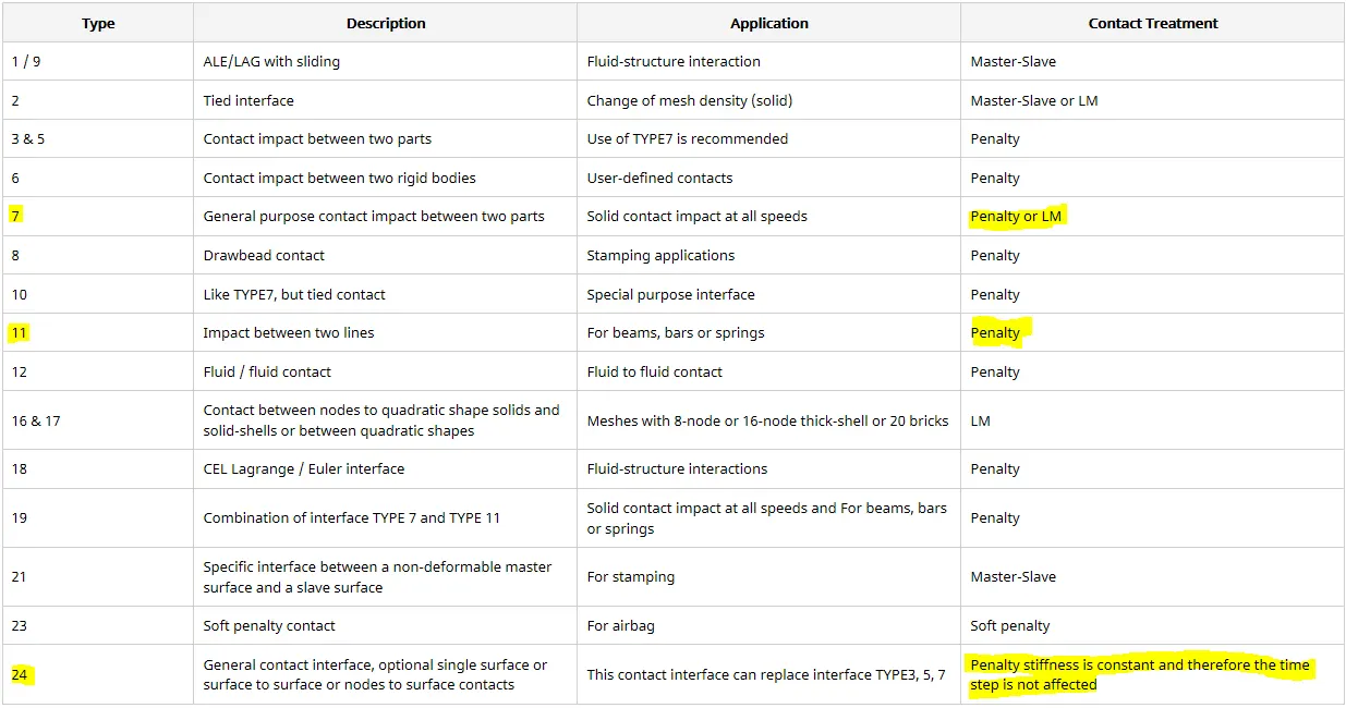
The highlighted are used commonly for all types of interfaces.
Type7: Non linear stiffness General node to surface contact,
Type11: Non linear stiffness edge to edge contact,
Type24: Linear stiffness node to surface contact and surface to surface contact.
Case1:
In this case the model is imported and ran with the default values. The TH/part is created and the parts are assigned.
Then the output file is saved in local directory path given.

The model follows the QEPH shell formulation. So the hourglass formation is zero and the energy error is almost not go to negative.
To see the simulation results the .h3d file is opened in the local file directory saved.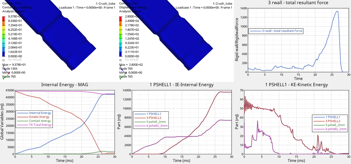
EXPLANATION:
The above image shows the contact forces, displacement forces. The plots shows the results for the total energy of the system,internal and kinetic energies of the parts and rigid wall forces.
Contact force:
The force that created during the impact of the two different elements due to deformation.
This force tends the tube to reduction in size and the elements to crush durin g deformation, while the penetration is zero till the force reaches the lower part of the tube and after some moments the contact force is created and the peak is attained makes the model to deform badly.
Displacement :
The displacement of the element are calculated. The lower part is not so much displaced because it is fixed and the upper part is displaced so ruoghly because of the rbody force is from the top.
Results from the plot:
The kinetic energy is high before the simulation starts because of the rbody force and it gradually decreases with increase in the internal energy of the system.
This means the energy is converted into other form of energy(kinetic to internal) and this makes the total energy of the system to remain constant straight line. Before the last time step the total energy decreases with the small increase in the kinetic energy. This is because the retracts the penetration of the slave node into the master segment.
The internal and the kinetic energies of the parts that created through the time history for the parts is plotted. In that the internal energies increases with the rapid reduction in the kinetic energy of the system.
Case2:
The same procedure is followed for this case too. The only change is the change in the initial penetration of the slave node into the master segment.
INITIAL PENETRATION:
Interactions results if the slave node are past the master segment(shell or bricks).
This condition can cause locking situation leading to computation failure. So the initial penetrations should be removed from the model suing hypermesh and hypercrash.
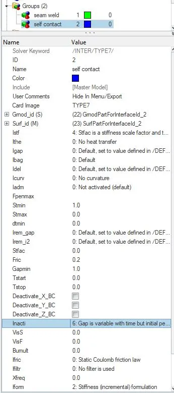
Penetrations result if the slave node is closer to the master segment than the calculated gap. Then the initial repulsive forces gives some error in the energy balance due to the contacts. To prevent this Inacti tool is used.
Inacti:
This option is having five variable types and eacha nd every variable is having a own characteristics.
The inacti=0,5 and 6 are commonly used variable inputs.
In the previous case the Inacti=0 is used. The main advantage of the Inacti=6 is it add some extra scale to the initial penetration gap(gap p_o=+5%).
The results for this case is saved in the local directory path file and energy differences are plotted.
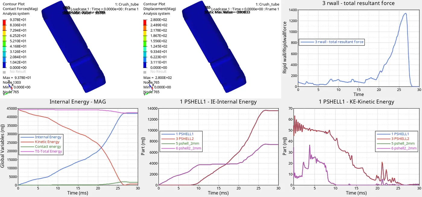
EXPLANATION:
The force that created during the impact of the two different elements due to deformation.
This force tends the tube to reduction in size and the elements to crush durin g deformation, while the penetration is zero till the force reaches the lower part of the tube and after some moments the contact force is created and the peak is attained makes the model to deform badly.
The displacement of the element are calculated. The lower part is not so much displaced because it is fixed and the upper part is displaced so ruoghly because of the rbody force is from the top.
Results from the plot:
The kinetic energy is high before the simulation starts because of the rbody force and it gradually decreases with increase in the internal energy of the system.
This means the energy is converted into other form of energy(kinetic to internal) and this makes the total energy of the system to remain constant straight line. Before the last time step the total energy decreases with the small increase in the kinetic energy. This is because the retracts the penetration of the slave node into the master segment.
At the end of the simulation the model is pushed back because of the resistive forces that push back the penetration of the element during the deformation.
Case3:
In this case the Type11 contact interface is used.
The main limitation of the type7 is that it cannot approach with the edge to edge contact interface. So that is covered in the Type11.
For most of the crash applications the type7 interface is used. So the combination of type7 and 11 is used in this case. The solver uses the edge to edge detection with the type 7 input parametres.

The highlighted are commonly used parametres in the crash applications.
PARAMETRES USED:
Slave and master: All components,
I_stf:affects how the stiffness of the interface is calculated(I_stf=4),
I_gap: Determines how the size of the gap is calculated(I_gap=2),
I_del: The deletion happens when the master segment is removed from the contact when all/one linked element is deleted and the slave node which becomes free that are removed from the contact. (I_del=2),
St_min: Specify a minimum stiffness in the contact to avoid too soft contact. (St_min=1000N/mm),
I_form: The formulation of the sliding forces using viscous/stiffness parametres of the interface. (I_form=2),
Gapmin: minimum gap defined for the activation of the interface. (gapmin>=0.5mm),
Inacti: restricts the initial penetration of the slave node into the master segment. (inacti=6).
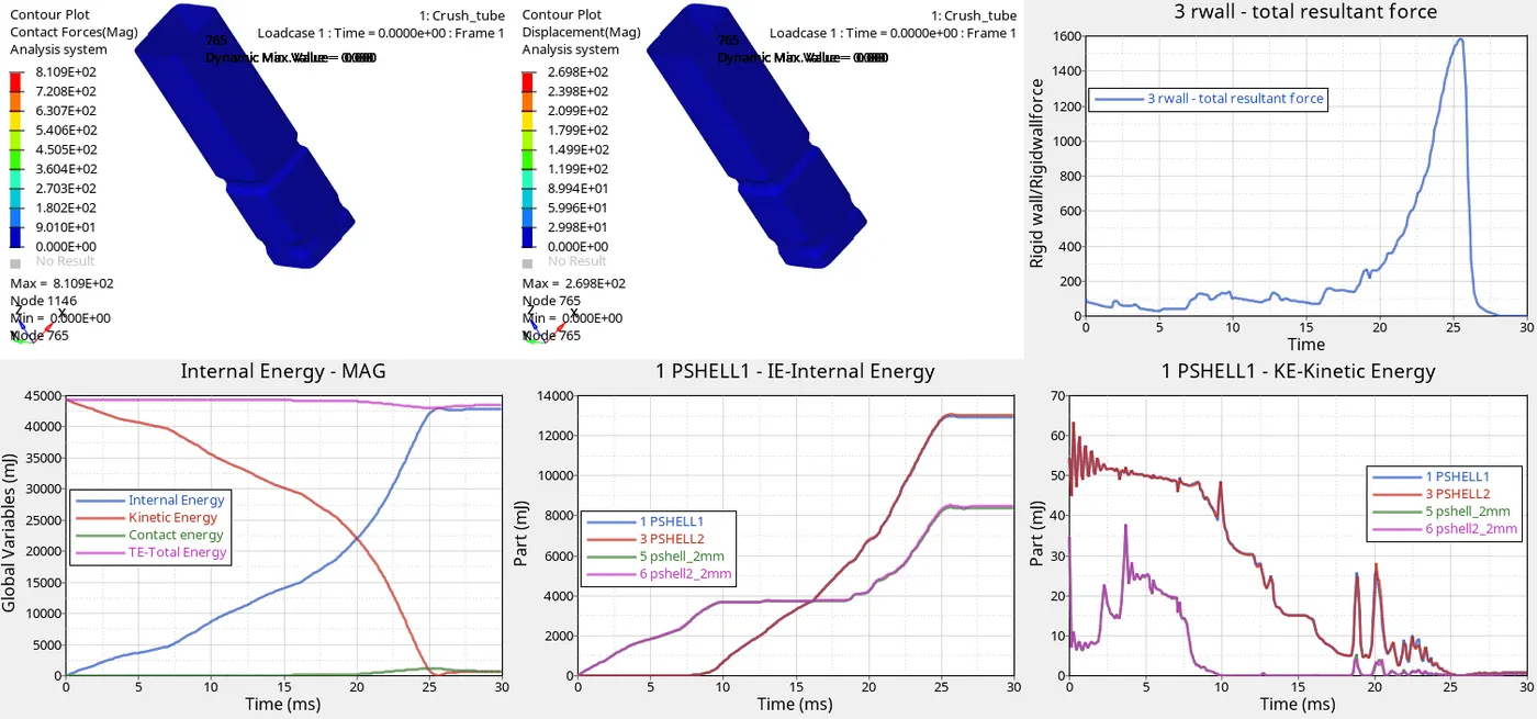
Results from the plot:
The kinetic energy is high before the simulation starts because of the rbody force and it gradually decreases with increase in the internal energy of the system.
At 25th ms of the simulation the force is fully stopped and the energy curve becomes constant till the last time step of the simulation.
This means the energy is converted into other form of energy(kinetic to internal) and this makes the total energy of the system to remain constant straight line. Before the last time step the total energy decreases with the small increase in the kinetic energy. The time taken by the solver to compute the energy changes are quicker in this case when compared to the other two cases before.
At the end of the simulation the model is pushed back because of the resistive forces that push back the penetration of the element during the deformation.
Case4:
In this case the notch in the model is aligned to the normal geometry and make it as flat in all sides.
This is done through the command Geometry--->node edit--->align or pressing the shortcut command shft+F8

After this step, check for the geometry issues.
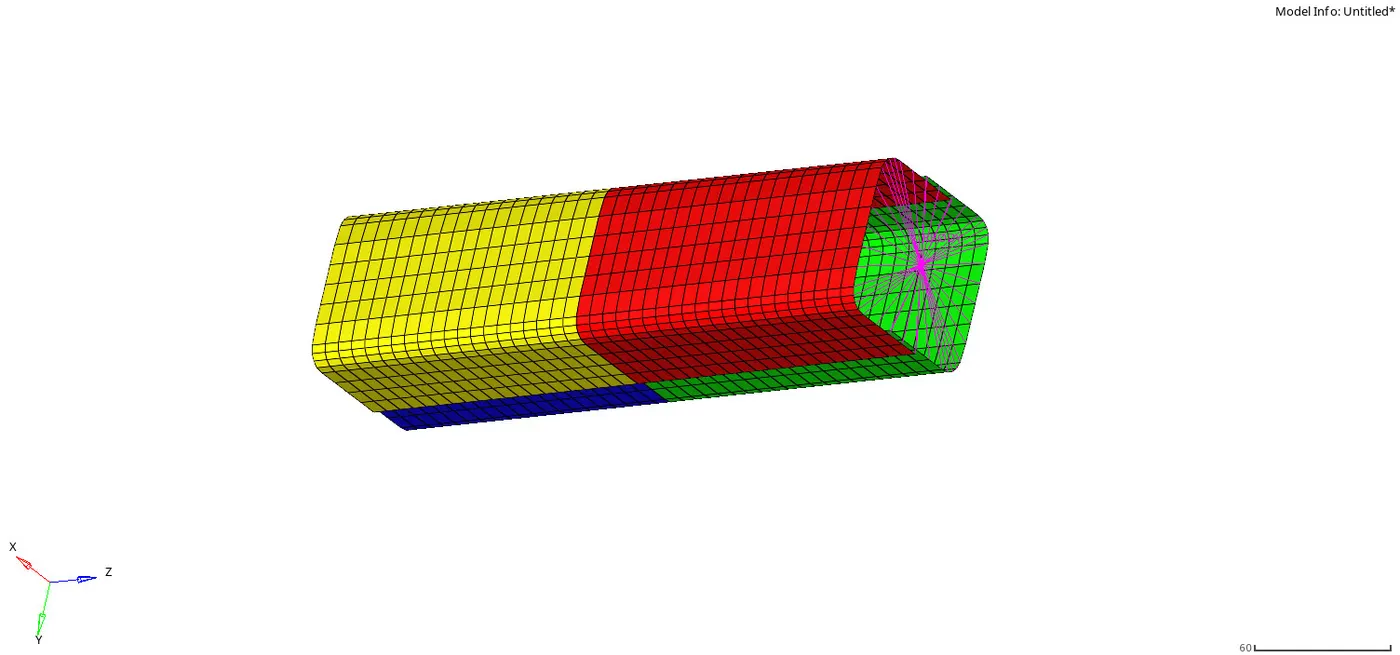
In this case the boundary conditions are deleted from the solver tab. When the boundary conditions(BCS)
are deleted the Degree of Freedom(DoF) for all the elements are free to move in any direction(both translational and rotational).
Then the analysis is done and the output file is saved in the local directory file path. To see the simulation results the .h3d file is opened.
The time history file is also created for all the parts in the model. Both the simulation results and the plots are shown in the below image.
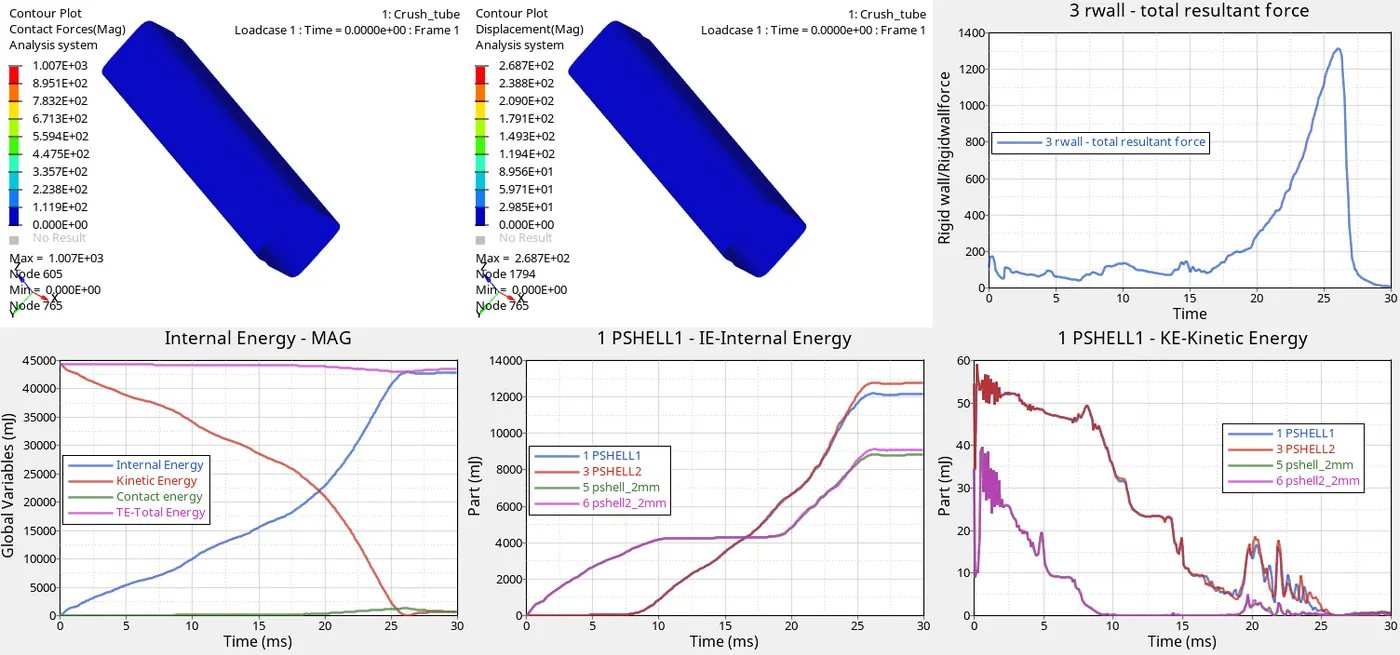
EXPLANATION:
The contact forces that is created from the start is displaced to the bottom of the model suddenly because there is no notch in the model. so the force is transfered all its energy to the bottom.
Due to the Rwall fixed the displacement is maximum at the top. And the displacement occurs at the all the parts of the model.
The deletion of the boundary conditions make the changes in the internal and the kinetic energies of the parts.
Due to the no bcs card the oscillation is more and the locking doesn't happens.
Case5:
In this case, the notch is created at the centre of the model(common for all the parts).
The type 11 interface is used with the bcs card is deleted.
Due to the type 11 interface the computation time for the solver is increased than the type7 contact. But the accuracy of the model is more in type11 than in the type7. 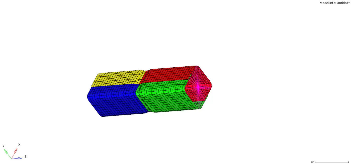
Then the analysis is done for the model and saved in the new lacal directory file path.
The .h3d file is opened to the simulation results.
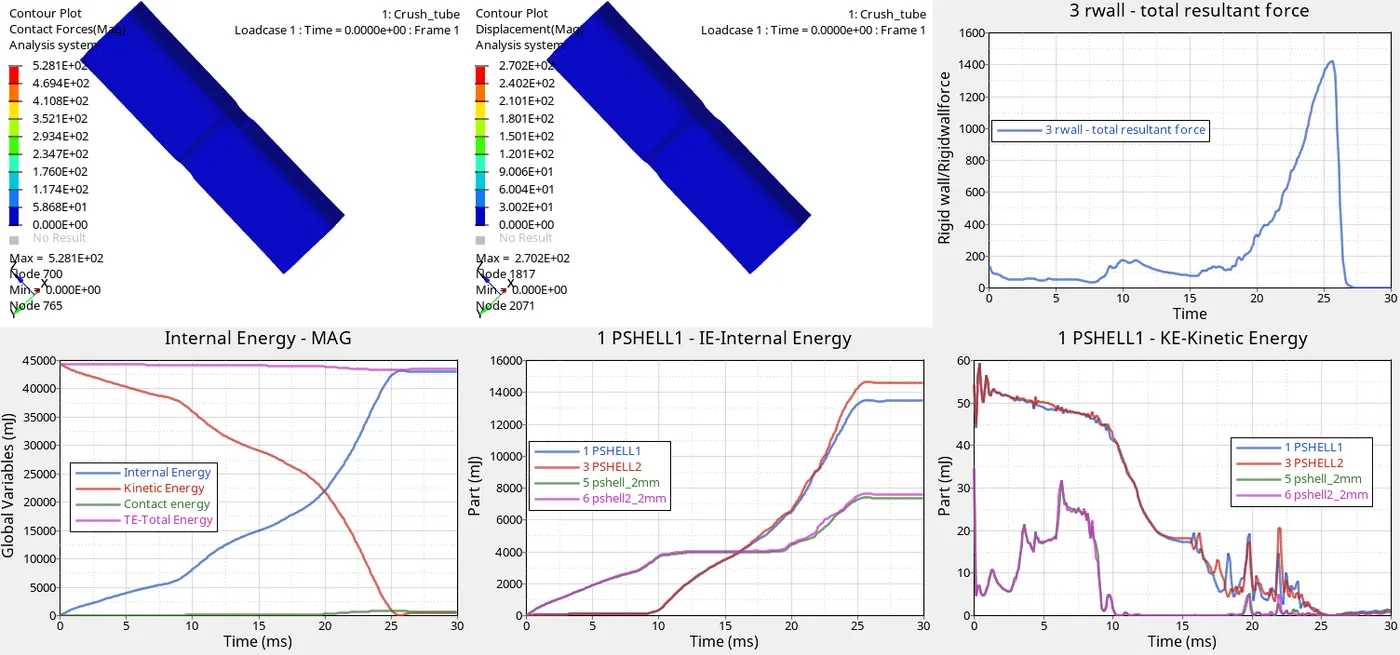
EXPLANATION:
The notch at the centre makes the deformation to starts at the middle of the model and the force is increased at the bottom. The bottom is fixed so the whole tube is flat at the end of the simulation.
Due to the dispalcement of the force from the top to the notch, it buldges at the middle and due to fixed point at the bottom it shrinks in the area.
The bcs card is deleted and the variation in the simulation are same as the previous model.
Case6:
In this model the notch is placed only at one face(horizondal or vertical face).
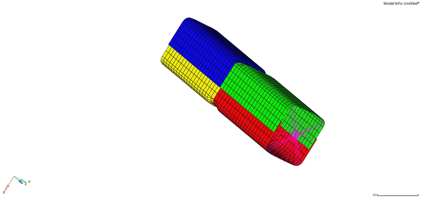
The notch is created only at the top of the face and opposite to it.
Then the simulation is ran for the model.
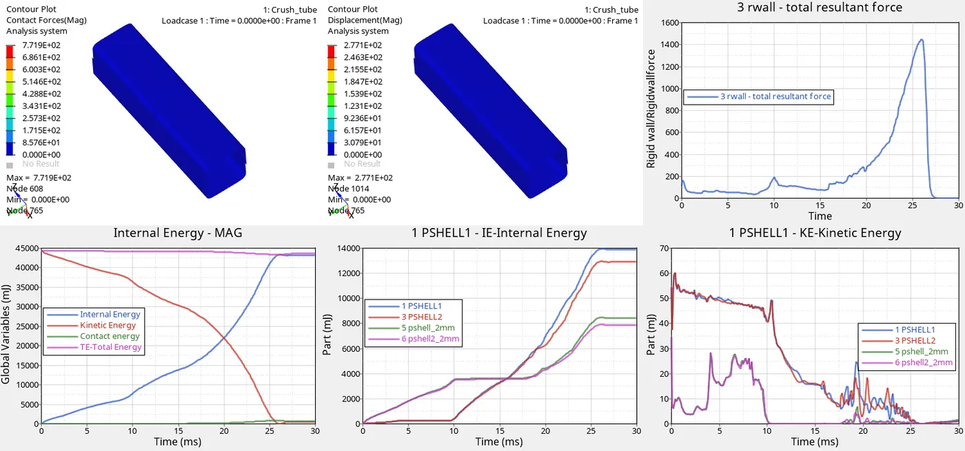
EXPLANATION:
Due to the notch at the middle of the model the force deforms the model from the middle that not having notch(vertical face) and the notch face is shrinked during the deformation.
The change in the kinetic energy and the internal energy of the body happens. due to the fixed point at the bottom(rwall) the tube crashed and becomes flat.
The internal energies of the parts are so high that it absorbed the kinetic energy of the rbody force. Due to the deletion of the bcs card the elements are deformed and spread to the different direction.
COMPARISON OF THE RESULTS:
All the 6 cases are compared to one another for the difference in the results.
Case 1,3,
Case 1,4,
Case 4,5,6,
Case 1,2 3,
Case 4,5,6.
Case 1,3:
In this comparison of case 1,3 is done. In case1 the default values are used and in the case3 the type11 interface is used with the type7 interface parametres.
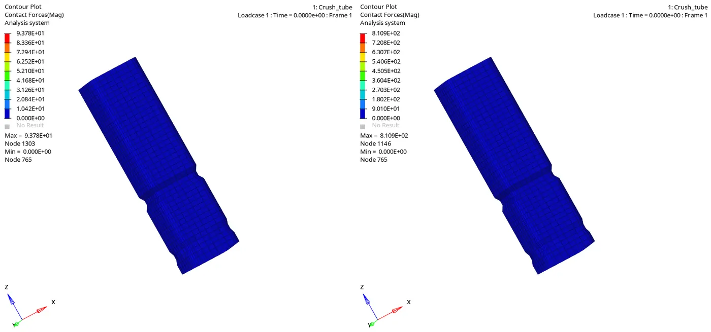
There is no any change to the shape of the model normal to the force. But at the end of the simulation the contact of the elements one with other happens more in the case3 because it is edge to edge contact and it is more accurate in nature so the simulation results are deeper than the case1 results.
With the type7 parametres the the initial penetrations are restricted and also during the impact and deformation the penetrations doesn't happens much more than in case1.
Case1,4:
In this comparison the notch section is compared. For case1 the notch is there but it is not even with the surface. There is also a dent in the end of the surface in case1.
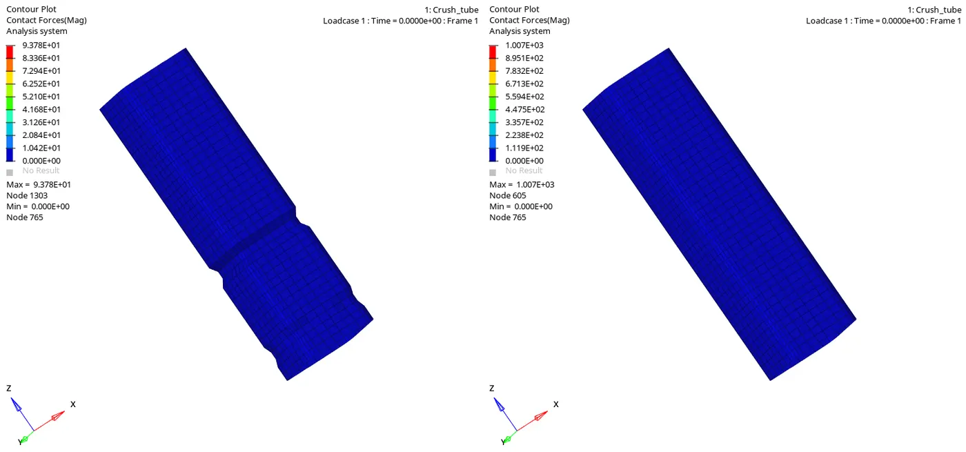
The case1 is having the default type7 parametres whereas the case 4 is has no notch and follows type11 parametres with type7 input values.
This makes the model to resists the more amount of penetration into the master segment. The amount of contact sorce created in the case3 is more than the case7 force creation during the simulation.
There is no any notch in the case4 makes it to drform from the bttom of the model. All the force are displaced to the bottom of the model. and at last the top of model is deformed.
Case4,5,6:
In the case5,6 the notch is created uniformly to the surface of the model at all the faces. But in case4 there is no any notch is present in the model.
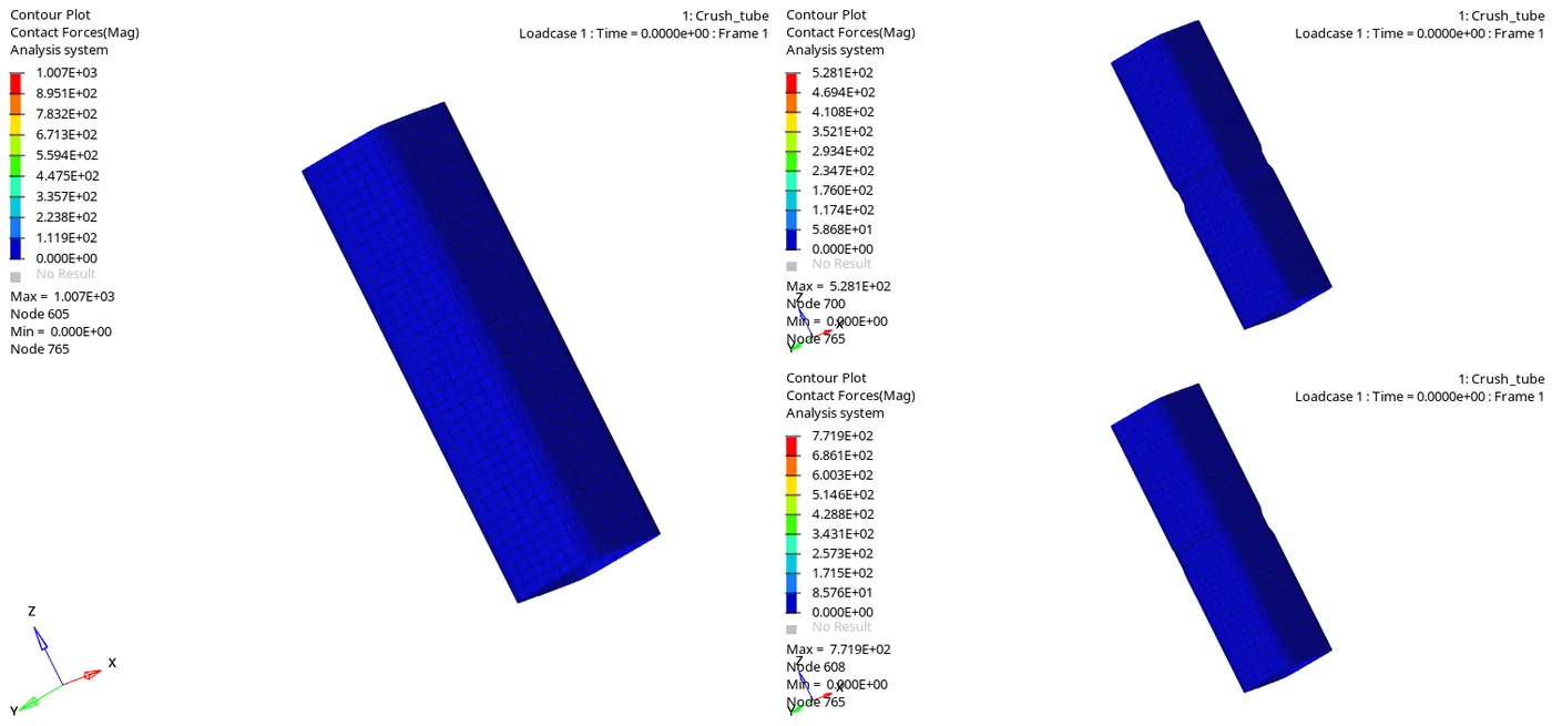
The case5,6 the force dissipation is low when compoared to the case4. The notch absorbs the impact first and the force is normal at the start to the end of the simulation making case5,6 more reliable.
Case1,2,3:
In this the plots are compared with each other cases to see the enrgy dissipation of the system due to the deformation.
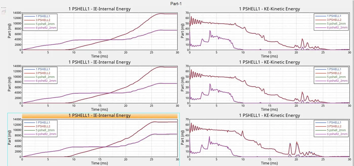
Both kinetic and the internal energies of the system is compared. The internal energy energy is zero before the simulation started because of the crash tube is in rest position. When the rbody force(kinetic energy) is applies to the model the force is converted to the energy and this energy is converted to internal energy of the system . The model is fixed at the bottom so the model doesn't fall due to the external push.
All the energies are not converted to the system fully because the internal energy is about `4000mJ but the kinetic energy is aboyt 70mJ
Case4,5,6:
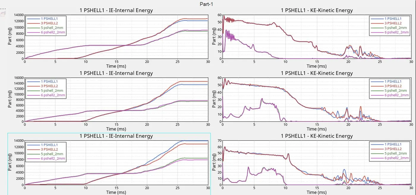 The oscillation is more for the case4,5,6 is because the boundary condition card is deleted and the type 11 interface is used for the three case .