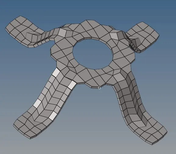
Assignment 1
CLEANING THE GEOMETRY AND CREATING A 2D MESH:
The given three models are meshed properly by cleaning all the geometry errors.
The following steps are used to finish the model, they are
Clean the geometry.
Extract midsurface.
Clean midsurface geometry.
Ignore holes less than dia 5mm.
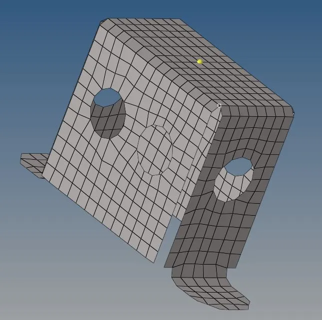
Create 2D mesh with target length 5mm, min 3.5mm max 7mm.
And assign proper thickness, by creating a generic property.
FIRST MODEL:
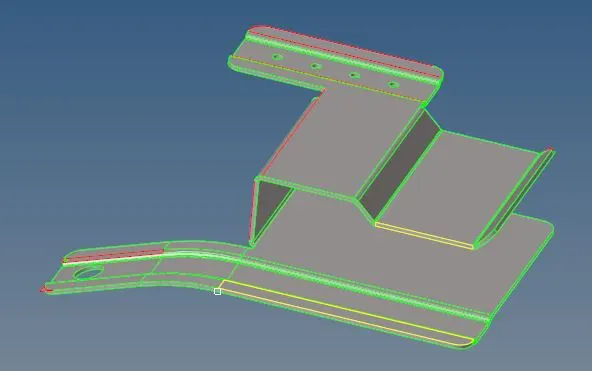
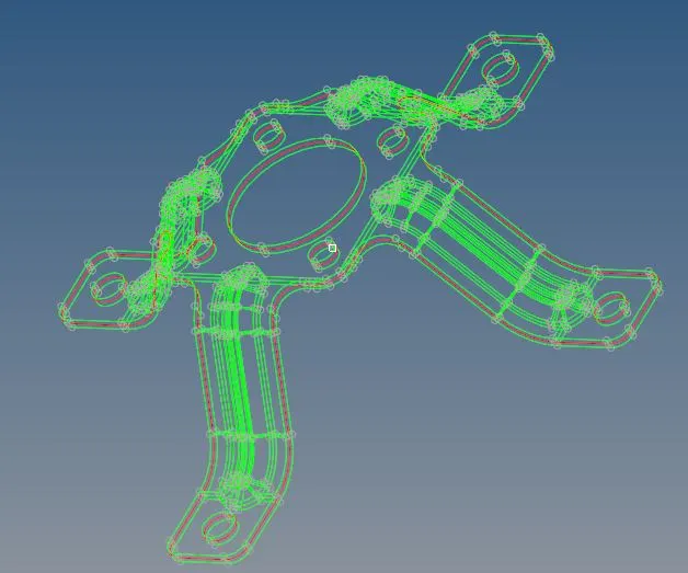
The red lines represents that free surface edges that not stiched together.
Green lines represents 2 surfaces are stitched stitched together.
The yellow lines represents the extra surface upper to the real geometry. It is formed when the two surfaces joined together.
cleaning the geometry:
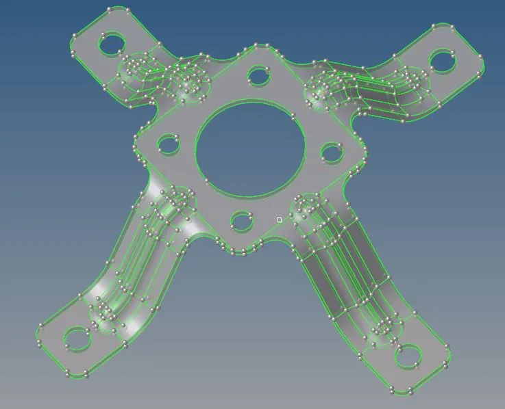
Cleaning the geometry means deleting the unwanted surfaces, extra lines, unwanted lines.
This is done through Goemetry ---> quick edit tab.

The option like toggle edge, filler surf and replace point are used to clear the geometry.
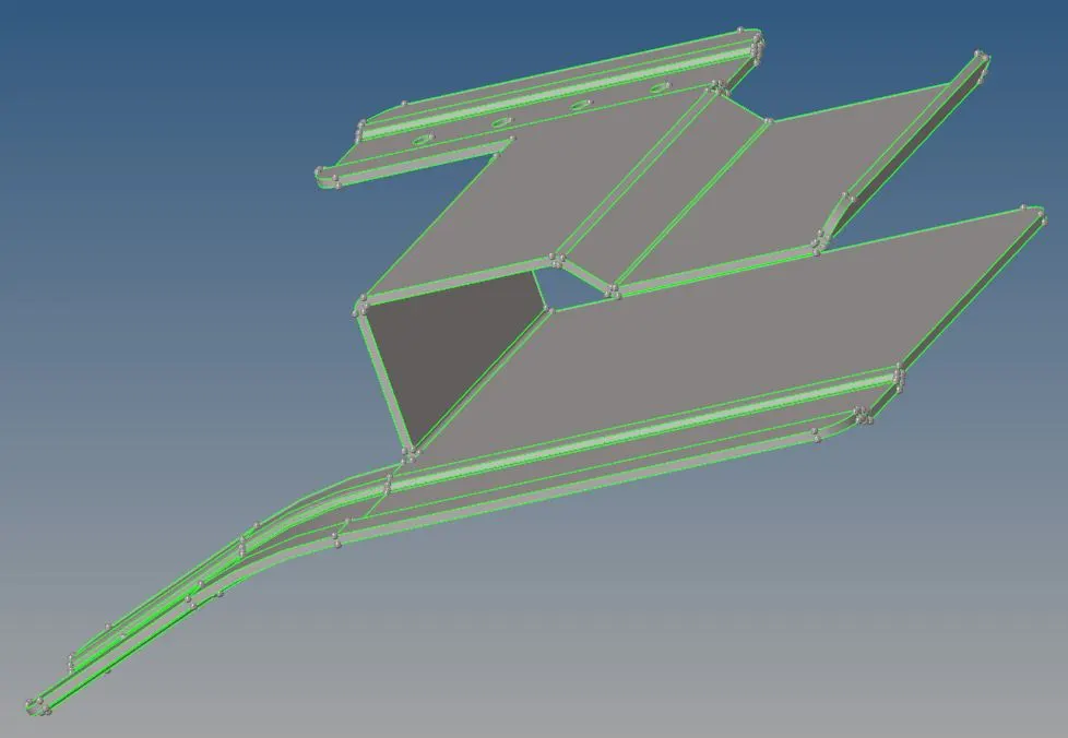
Now all the errors are cleaned up and all the lines and all the edges are toggled correctly.
Extracting Midsurfacing:
The midsurfacing is the process of creating the new surface(baby surface) in between the parent geometry. This is also known as offsetting process.
The midsurface option is done through geometry ---> midsurface.

The newly created surface is in one colour and the parent geometry is in other colour. It is represented in the model view tab.
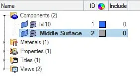
In model view the geometry and elements of the model's are viewed and hide by clicking on it.
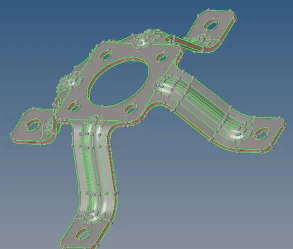
To verify the midsurfaced geometry the wire frame geometry is clicked to view the wireframe.
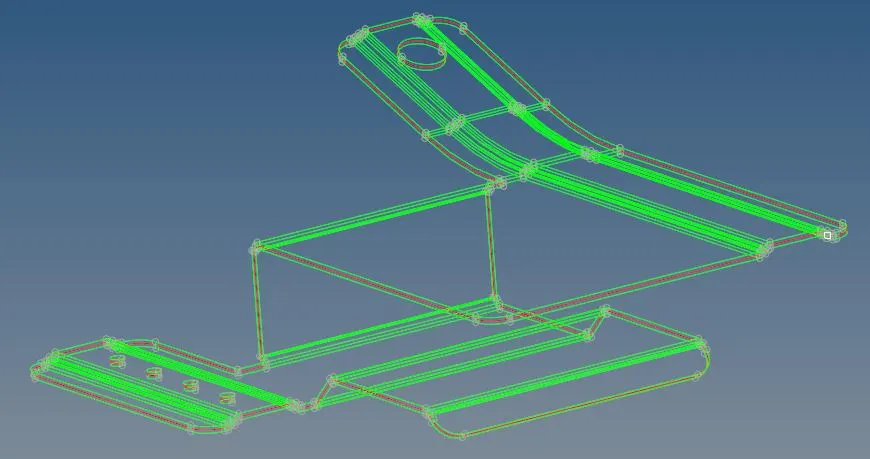
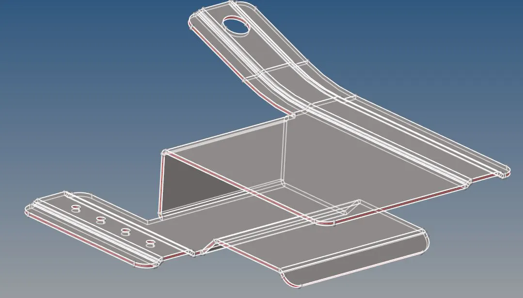
wireframe geometry shaded geometry
cleaning the midsurface geometry:
To clean the midsurface geometry the holes less than 5mm are removed from the geometry. This is done through geometry---> quick edit ---> fill surf and then toggle edges.
The unwanted points all over in the model is removed because the mesh quality is affected by the extra points in the geometry. That is done by going to geometry --->quick edit---> add/remove points option.
creating 2D mesh:
The 2D mesh is done only for the middle surface and then is is assigned some thickness from the parent goemetry.
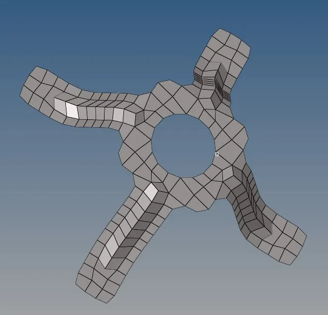
The meshing is done through the command 2D--->automesh---> selecting the surf---> assigning the element size--->mesh.
Tria element mesh:
This cell shape consists of 3 sides and is one of the simplest types of mesh. A triangular surface mesh is always quick and easy to create.The tri elements are ignored because the stress distribution in tri elements is constant but in a quad element stress is linearly changing. It is also stiffer than the quad element resulting in less stress values and distribution.
Quadrilateral mesh:
This cell shape is a basic 4 sided mesh element. Only quad elements are meshed in the surface to be meshed. If the element is linear in nature it is easy to give some load conditions on them.
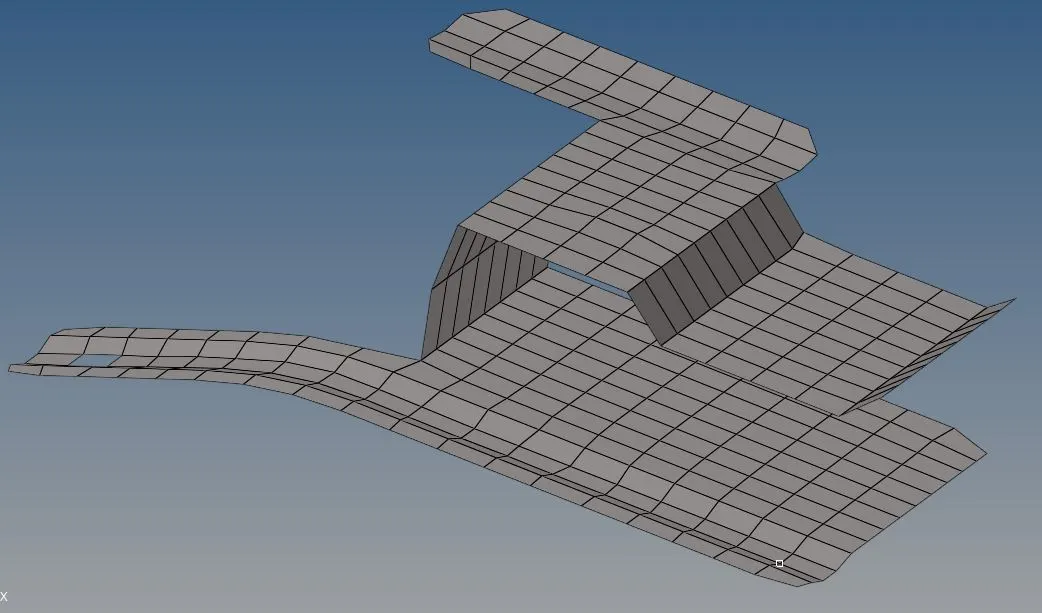
Aligning: The process of arranging all nodes of the mesh in a same line.
Smoothing: The process of smoothening or equally space the mesh.
Split: The process o0f spliliting the element into two. This is done only to get through the tri elements into quad type.
Paste: The option to clean the tri element.
Equivalence: The process of connecting all free edges.
Project: The element which is out of the geometry is rectified through this option.
Mesh style: This command is used to edit the mesh quality.
Reflect: The process of reflecting the selected meshed surface into the other surface bay creating the plane of symmetry between the two surfaces.
quality checking:
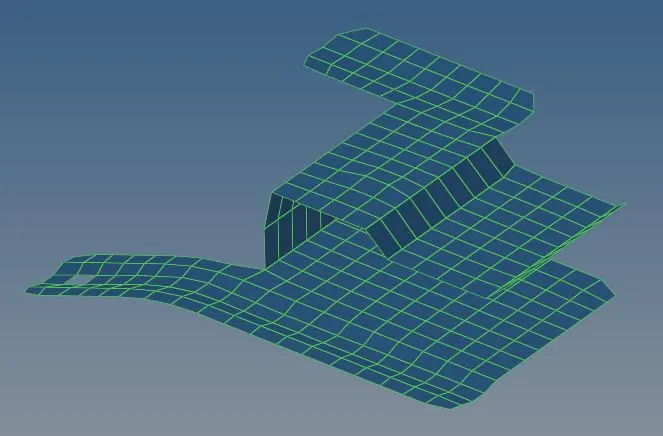
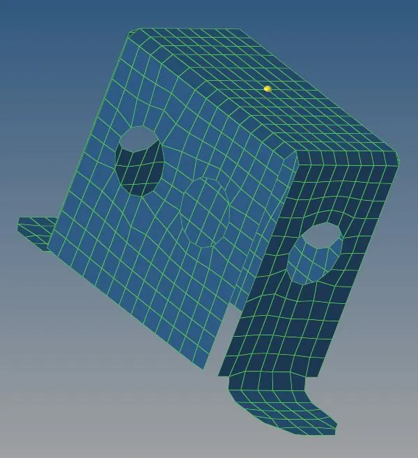
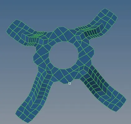
The process of checking the quality of the mesh created. This was done through 2D--->quality index.

The size for the mesh is assigned and the tab through us the results.
yellow colour denoted that the mesh is failed.
red colour colour denoted that the mesh isworst in nature
light blue colour denoted that the mesh is fair.
blue colour colour denoted that the mesh is good and ideal in nature.
Assigning thickness to the mesh:
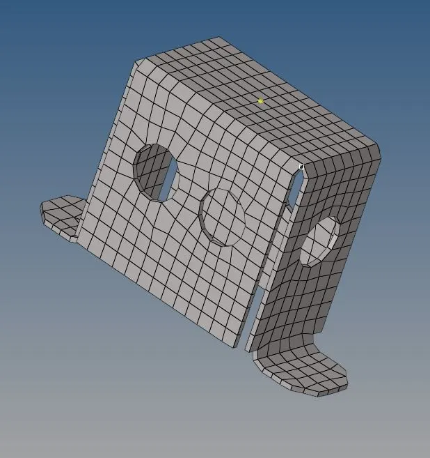
The thickness giving is done by taking the parent geometry dimension and assign it to the meshed geometry.
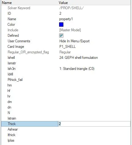
The property is assigned with the thickness value and it is viewed in its original goemetry after applying the thickness value.
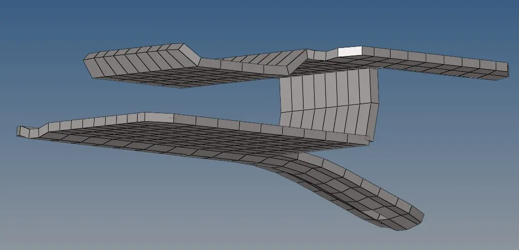
similarly the second and the third model are done
second model:
geometry clean up:
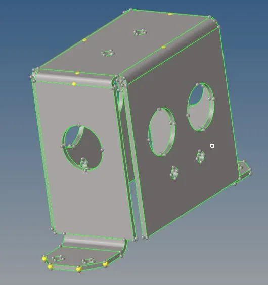
Midsurfacing:
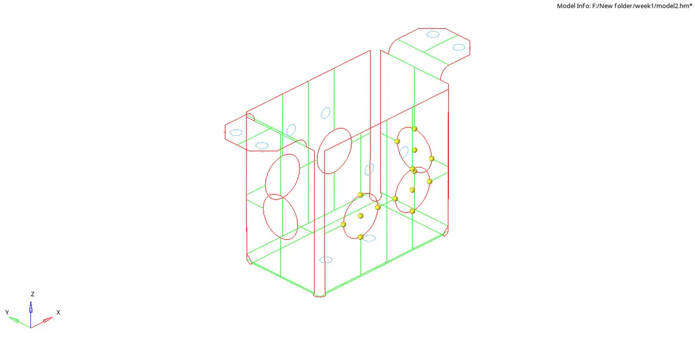
Midsurfacing geometry cleanup:
The unwanted holes like below 5mm are filled and toggled using quick edit option.
The free edges are also cleaned up.
Meshing:
Quality checking:
Thickness assigning:
Third model:
geometry clean up:
Midsurfacing:
Midsurfacing geometry cleanup:
The unwanted holes like below 5mm are filled and toggled using quick edit option.
The free edges are also cleaned up.
Meshing:
Quality checking:
Thickness assigning: