Dynamic Transient Bird Strike Simulation using LS-DYNA.
AIM:
To simulate a non-linear transient dynamic problem of a Bird Strike with a Jet Engine Blade and evaluate the results.
GAS TURBINE ENGINE:
Both Piston (reciprocating) engines and Gas turbine engines are Internal Combustion engines. They have a similar cycle of operation that consists of intake, compression, combustion, expansion, and exhaust. In a piston engine, each of these events is a separate distinct occurrence in each cylinder. Also, in a piston engine, an ignition event must occur during each cycle, in each cylinder. Unlike reciprocating engines, in gas turbine engines these phases of power occur simultaneously and continuously instead of one cycle at a time. Additionally, ignition occurs during the starting cycle and is continuous thereafter.
The basic gas turbine engine contains four sections: intake, compression, combustion, and exhaust.
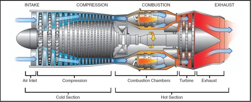
To start the engine, the compressor section is rotated by an electrical starter on small engines or an air-driven starter on large engines. As compressor R.P.M. accelerates, the air is brought in through the inlet duct, compressed to high pressure, and delivered to the combustion section (combustion chambers). Fuel is then injected by a fuel controller through spray nozzles and ignited by igniter plugs. Not all of the compressed air is used to support combustion. Some of the compressed air bypasses the burner section and circulates within the engine to provide internal cooling.
The fuel/air mixture in the combustion chamber is then burned in a continuous combustion process and produces a very high temperature, typically around 4,000°F, which heats the entire air mass to 1,600 – 2,400°F. The mixture of hot air and gases expands and is directed to the turbine blades forcing the turbine section to rotate, which in turn drives the compressor by means of a direct shaft.
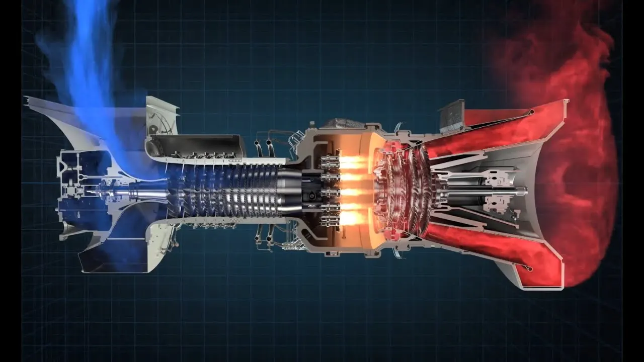
After powering the turbine section, the high-velocity excess exhaust exits the tailpipe or exhaust section. High-pressure exhaust gases can be used to provide jet thrust as in a gas turbine engine. Once the turbine section is powered by gases from the burner section, the starter is disengaged, and the igniters are turned off. Combustion continues until the engine is shut down by turning off the fuel supply.
Bird-Strike Impact:
A bird strike is a collision between a bird and an aircraft. Bird strikes have always been a cause of worry in the aeronautical industry. Aircraft both old and new have suffered from bird strikes. Jet engine ingestion occurs when the bird hits the jet engine of an aircraft and gets sucked in. Given that the fan blades rotate at a high rpm, a bird strike on a fan blade causes its displacement into the adjacent blade. This leads to a cascading failure, wherein the entire system fails, thereby resulting in a lot of damage.
Several bird models were proposed, each more effective than the other. A bird could be thought of as behaving like a fluid when undergoing high-speed impact. Some of the models propose an elastic-plastic deformable body with a low value of yield point and small hardening, while others consider a hyper-elastic (rubber-like) body, the jelly-like body which easily splatters over the whole blade, a liquid body, or even particles of a solid body.
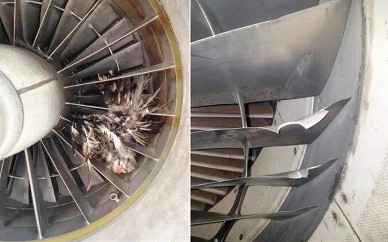
The Bird-Strike damage can be very severe and can shut down the jet engine. as shown below. This is the behavior we are trying to simulate for the damage done from the bird strike.
Steps followed in this simulation:
Save the different parts of the engine into different (.k) files.
Numbering the elements, nodes, and other keywords as per the given standard.
Assigned the section and material for each part card for a separate component of an engine.
Define the boundary conditions to the associated parts.
Define the contacts between the parts and the database within a single keyword file.
Defined the Control and Database card for the relevant postprocessing result.
Include all the cards into the main file and run the solver after saving it.
Results and conclusion.
PROCEDURE:
Open the Project file:
The given project file contains four different parts, hub, blades, engine casing, and bird respectively. So, these parts are separated and placed into a single input file. Here we are going to simulate the effect of the classic bird strike impact on the gas turbine fan blade. The various engine parts along with control, contact, and database cards are included in the main file. The elements, nodes, and parts are renumbered in an organized way as per industry standards.
The condition we carry on with this project is blades rotate at a constant velocity and the engine casing should remain stationary. The cylindrical bird should travel along its own axis toward the engine and hit the blades. At last, all the separate parts files should be in a single input file (.k file) and are called into the main file through the *INCLUDE keyword. The unit system chosen for this analysis is kg-mm-ms. and should have consistent numbering.
Note: The Young’s modulus for the bird is given as 2000MPa and the casing is given as 200GPa. Both bird and casing are modeled by an elastic material, the elastic material properties defined for the bird with the density and Poisson’s ratio values are taken similar to human muscle values. Similarly, the engine casing is defined with properties that are similar to the metal.
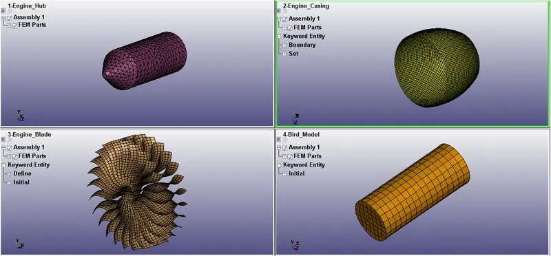
We will save the different components of the engine under different file names (such as shown below in the figure) so that they can include in the Main file along with boundary conditions.
 ---->
---->
There will be a single Bird_strike.k file containing all the part numbers in an unorganized way, that we need to save them under a different name so that they can be numbered easily and later included in the Main file.
Numbering the elements, nodes, and other keywords as per the given standard:
Individual saved files are now opened and with help of Renumber option available one by one node, element, the part can be renumbered as per the given standard.
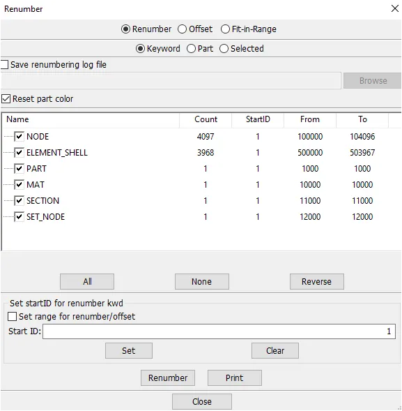
The command used for renumbering is Toolbar--->Model and part--->renumber.
Assigned the section and material for each part card for a separate component of an engine:
a. Engine Hub
Similarly, for the hub, we will assign the material(MAT_024), Section(solid), and part to the individually saved Hub.k file.
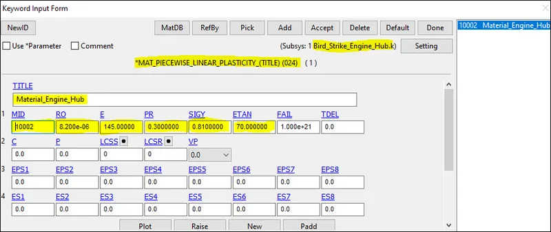
The Hub is represented as a solid element with element formulation of equals 10 for the tetrahedron. The E value assigned is 145 Gpa and a high FAIL value.
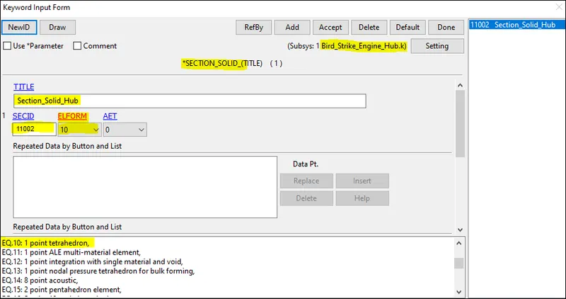
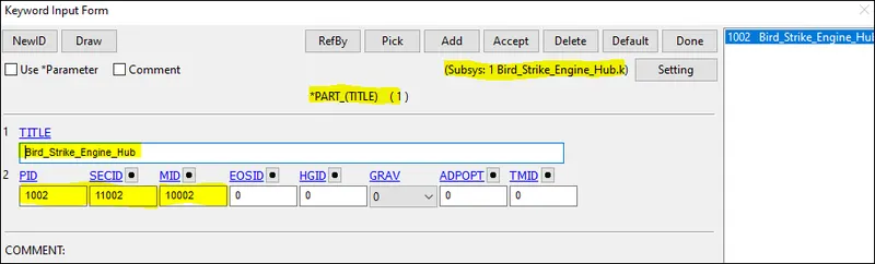
After creating the material and section cards the part ID is updated.
b. Engine Blade:
Here we will assign the material(MAT_024), section(shell), and part to the individually saved blade.k file, but here we will include the material file given question assign that material to the part card.
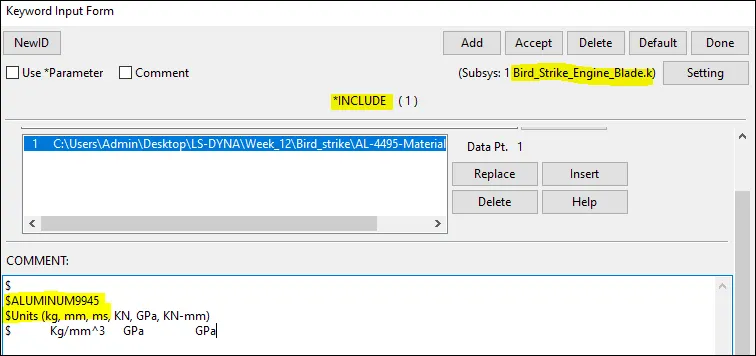
As we can see that E= 68.94 Gpa and FAIL = 0.2723 which means the material will fail when it reaches 27.23 % of the plastic strain value. the thickness assign to the shell section is 3mm for the blade.
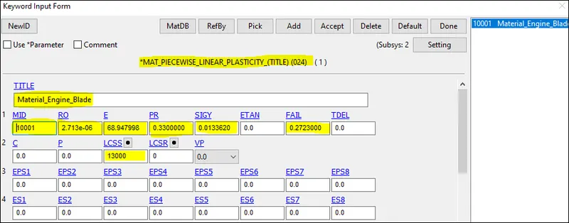
Here we will only mention material ID which is the same as above in the material card for the blade material definition.
Load curve definition:
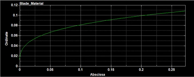
Below is the data of the material that we have input to the blade material card through LSID (13000).
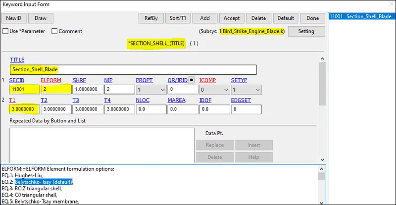
Then the section card containing Shell properties are created with the thickness of 3mm and ELFORM as 2(Belytschko-Tsay, default).
After creating the material and section cards the part ID is updated.
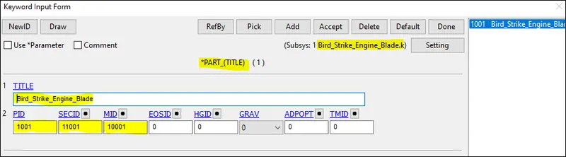
c. Engine casing:
We will assign the material(MAT_024), section(shell), and part card for the component inside the individually saved files i.e. casing material data inside the birdstrike_casing.k
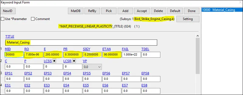
As given the casing material young modulus has to be kept 200Gpa with all other data assumed near to steel with FAIL value very large tending, not to fail. the thickness defined in the shell card is 5 mm.
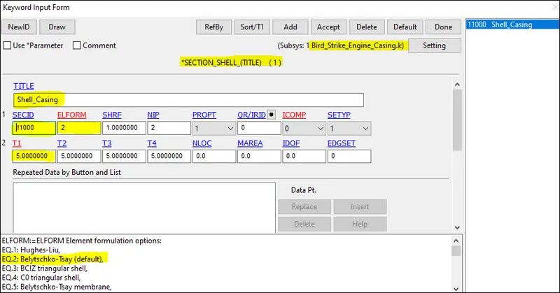
After creating the material and section cards the part ID is updated.
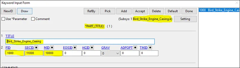
d. Engine_Bird:
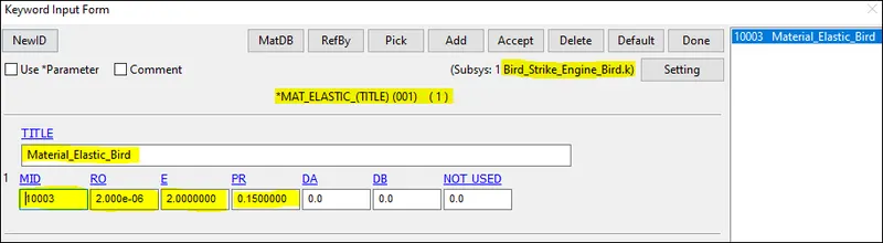
For the bird model, we will use the MAT_Elastic (001) and shell section thickness 6 mm and Young modulus as 200Mpa or 2Gpa and poison ration 0.15 and low-density value as we need to replicate a bird into the simulation.
It would be better if we represent the Bird with the smooth particle hydrodynamic (SPH) as it is a soft body impact in structural analysis the bird impact can be considered as a fluid material.
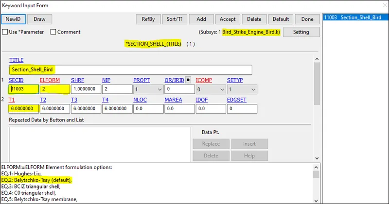
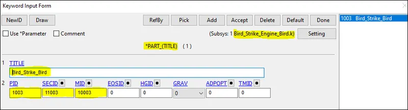
After creating the material and section cards the part ID is updated.
Defining the boundary conditions to the associated parts:
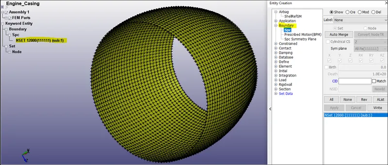
a. Engine casing:
Fixing all the DOF of the casing nodes as shown below using a single point constraint(SPC).
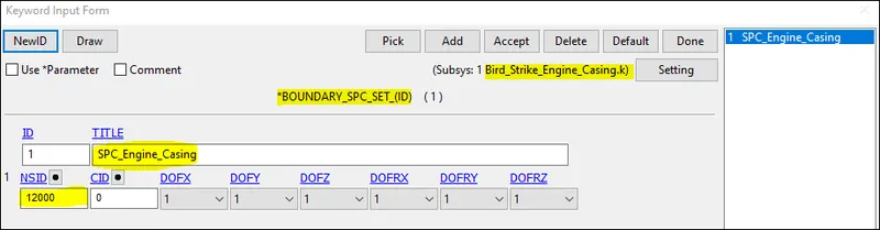
The SPC set is created using Model--->Create Entity--->Boundary--->SPC--->Create.
b. Engine_Blade:
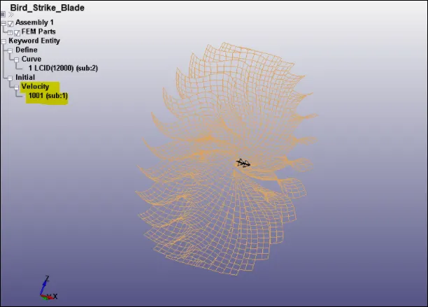
We will assign the Initial velocity generation of Omega(w)= 0.5 rad/ms. Assume the speed of the blade is nearly 5000rpm then
`(2piN)/60=(2*pi*5000)/60` =523 rad/s = 0.523 rad/ms = 0.5 rad/ms.
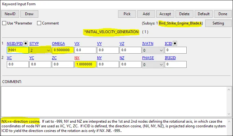
The angular rotation about rotational axes is represented in the Initial velocity generation card as omega=0.5rad/ms.
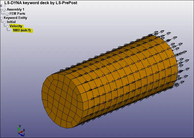
c. Engine_Bird:
Assign the Initial velocity Generation of 20 mm/ms(72 kmph) in the X-direction.
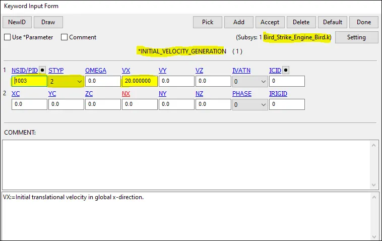
The Bird model is inputted with the velocity in Translational X-direction in mm/ms.
Defining the contacts between the parts and the database within a single keyword file:
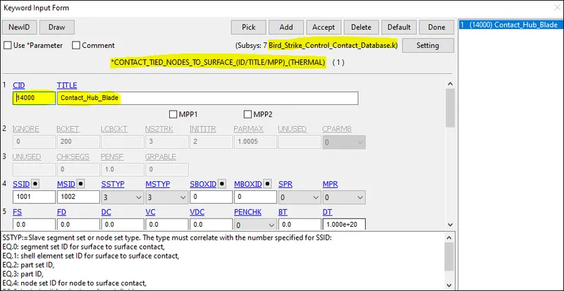
Contact between Hub and Blade:
A Tied node to surface contact is defined between hub and blade as it is an integrated unit and should rotate along with the blade at a similar angular speed. The master is assigned to Hub and the slave to Blades.
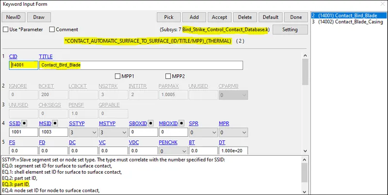
Contact between Blade and bird:
Automatic surface to surface contact is defined between the blade and bird interface with the master node as bird and blade as slave nodes. As we need to observe stress and strain developed in the fan blade, therefore, it is defined as a slave.
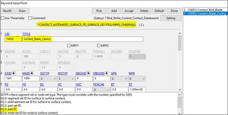
Contact between blade and casing:
Automatic surface to surface contact is defined between the blade and casing interface with the master node as casing and blade as slave nodes.
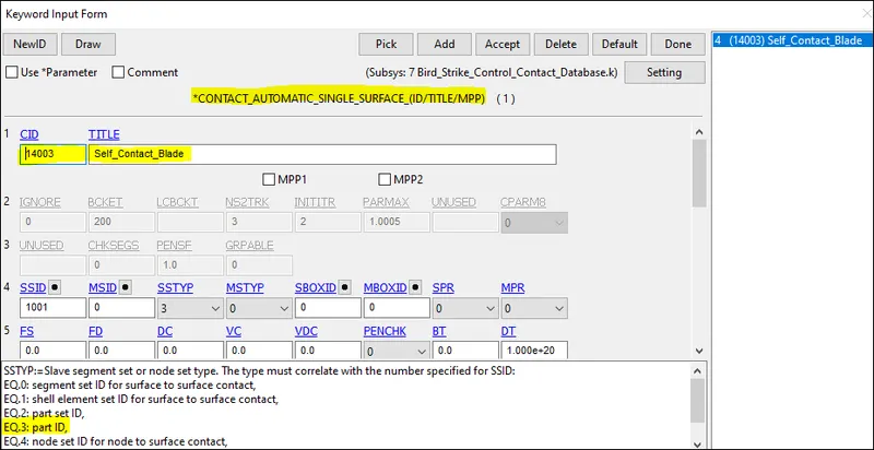
Contact for blade ie, self contact:
The Automatic single surface contact is defined for the blade self contact. with the master as 0 and slave as the blade.
Defining the Control and Database card for the relevant postprocessing result.
a. Control cards
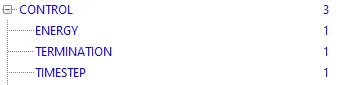
Define control cards for Energy, termination, and Timestep as shown below.
Termination time setup is 4 ms and Energy card to take into account hourglass energy with hgen=2.
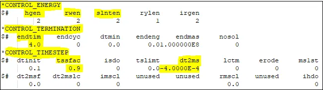
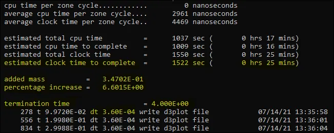
The Control Timestep card plays an important role in reducing the runtime. we can have a different combination of DT2MS and TSSFAC to check the estimated runtime and % mass added during mass scaling. Here we will try to keep the percentage of mass added below 7% and reduce the runtime.
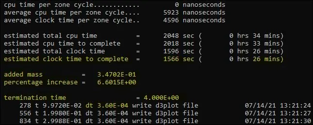
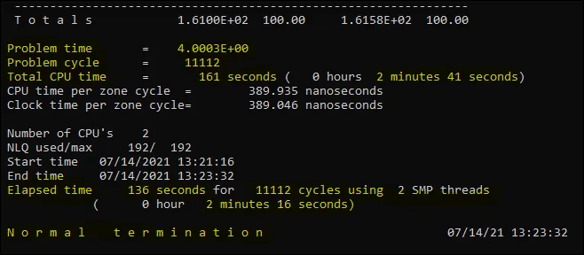
In 1st trial, we did this by keeping DT2MS = -6.0E-06 and TSSFAC=0.9 the runtime estimated is 26mins but actually, it took 2min 16 secs mass addition.
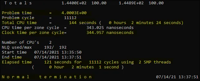
In the 2nd trial, we did this by keeping DT2MS = -4.0E-04 and TSSFAC=0.9 the runtime estimated is 25 min but actually, it took 2 min 1 sec with 6.6% mass addition. (Acceptable)
By changing the Control timestep criteria there are no big changes that happened in the simulation.
b. Database Card
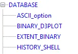
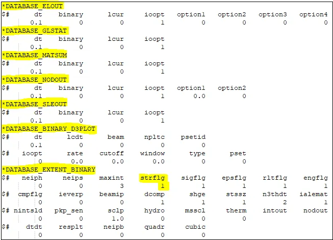
Among the Database card, we will include ASCII, D3PLOT, EXTENT_BINARY (for strain data in post-processing)
Include all the cards into the main file and run the solver after saving it:
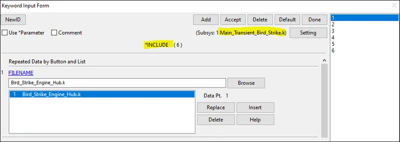
The Main_Transient_Bird_Strike.k file will include all the files i.e components, material, section, part, boundary condition, contact, control, and database.
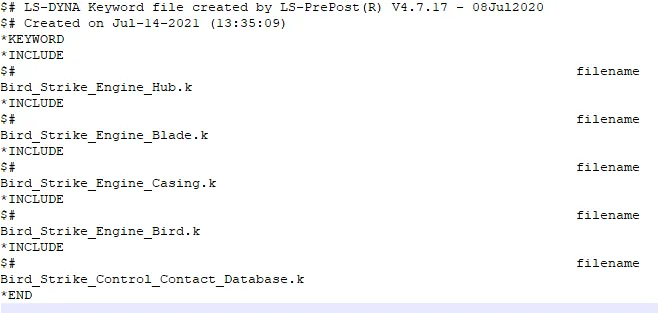
To verify that all the key files are included in the main file, the Main file is opened using Notepad++.
RESULTS:
Energy plots:
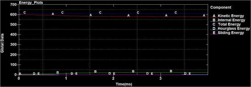
The 1st level of check to validate the accuracy of the simulation is done from the energy plot, we can see the Total Energy is almost constant over the period of simulation which indicates the result simulation run well.
There is no significant change in the energies due to the impact. The system possesses large energy due to the rotation of blades and the impact is not that severe to change the existing energy significantly. Hourglass energy is zero throughout the simulation.
The Kinetic Energy and Internal Energy show a very similar pattern during the simulation where K.E reduces and I.E increases thus the Total Energy remains constant all over the impact.
Von-mises stress plot:
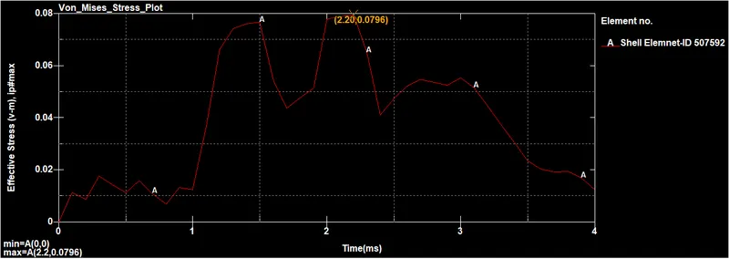
This stress plot is taken on one of the element of the blade where the impact takes with the bird at every time, but the stress peaks and reaches a value of 0.0796 Gpa at the (time of 2.20ms )moment of impact and drop to a value of 0.01 Gpa at the end of the simulation.
Plastic strain plot:
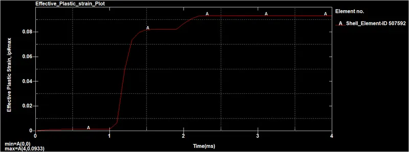
This strain plot is taken on one of the elements of the blade where the impact with the bird. At t= 2.3ms the strain values peak to 0.0931 i.e. 9.31% strain then is constant throughout the simulation.
Contact plot for blade_Bird:
The energy plot between the blade and bird contact is shown below, that before the interaction of the surface the energy was zero but nearly from 1ms the energy within the contact starts to develop. The energy conversion between the slave(blade) and master(bird) is symmetric. the maximum value of energy developed is 7.86 units at t= 1.20 ms.
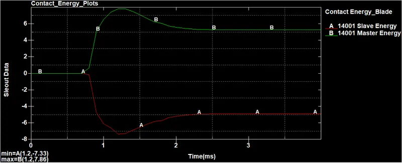
It can be seen the energy values changes for the bird drastically. This is because the bird possesses kinetic energy because of the linear velocity at the start. This energy drops down by a certain amount due to the impact and the bird changes its path with some extra velocity imparted by the rotating blades. This increases the kinetic energy further after the impact and the internal energy is also increased by some amount due to the collision. But the energy levels are less and not that significant compared to global energy.
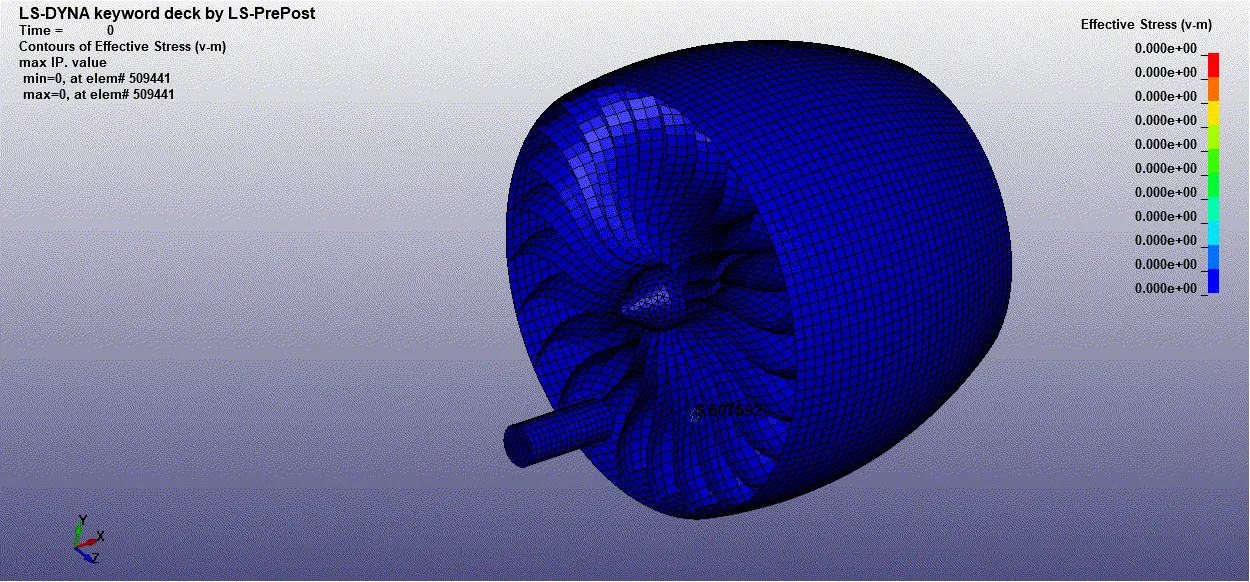
Von- Mises Stress animation for Bird- Strike Impact:
Effective plastic Strain animation for Bird- Strike Impact.
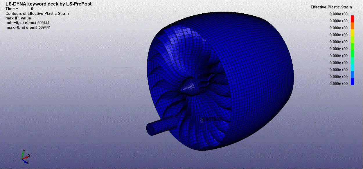
OBSERVATION:
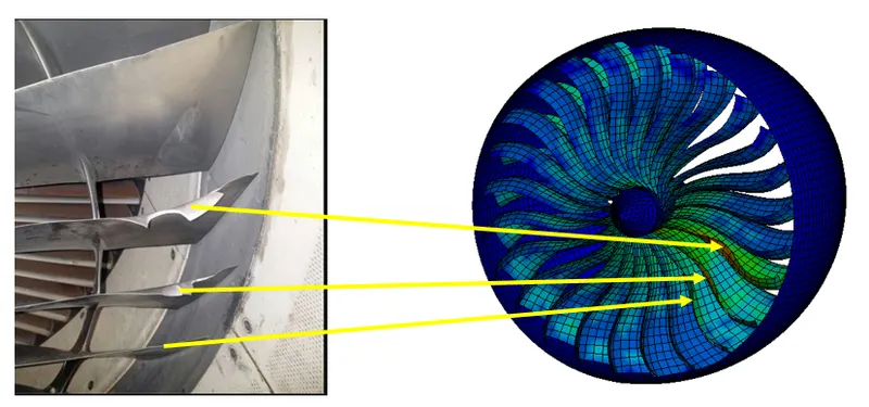
CONCLUSION:
All the components followed a consistent number pattern for each element, node, and part, as followed in many industries, and all the files such as for parts, Boundary conditions, contact, control, database, are included in the Main file also the Boundary conditions and initial velocity conditions are deployed in the same real-world scenario.
From the energy plot, we can observe that Total Energy is constant over the simulation which represents the simulation runs well.
The max Von_Mises stress produced in the fan blade is 0.0793 Gpa at nearly 2.2ms of simulation. The max strain developed is 0.0931 at 2.3ms of simulation and remains constant over the simulation.
For Mass-scaling, the mass added is 6.60% which below the accepted range ie, 7%. The analysis would be more promising to represent real behavior if we model the bird as an SPH.
The Transient bird strike impact analysis is performed in the LS-Prepost. From post-processing, the severity of the bird impact on the blades is analyzed. There is some permanent deformation in the blade which is impacted by the bird. There is no significant change in global energy.