Rearview mirror solid meshing using ANSA
ABSTRACT:
To create a 3D TETRA MESHING using the given quality criteria file and check for the quality at the end of the meshing. THe 3D mesh is achieved by boing the 2D mesh first and the 3d mesh is done finally.
3D MESHING:
The goal is to create a mesh that accurately captures the input domain geometry, with high-quality, well-shaped, cells. The mesh should also be fine in areas that are important for the subsequent calculations. The 3 dimensional meshed elements are clasified into two different types, they are
Structured mesh (or) mapped mesh,
Unstructured mesh.
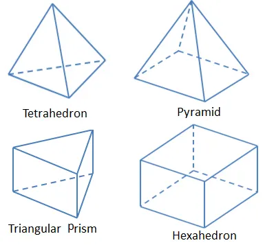
Structured mesh:
Structured grids are identified by regular connectivity. The possible element choices are quadrilateral in 2D and hexahedra in 3D.
This model is highly space efficient. Some other advantages of structured grid over unstructured are better convergence and higher resolution.
Unstructured mesh:
An unstructured grid is identified by irregular connectivity. It cannot easily be expressed as a two-dimensional or three-dimensional array in computer memory. This allows for any possible element that a solver might be able to use.
Compared to structured meshes, this model can be highly space inefficient since it calls for explicit storage of neighborhood relationships. These grids typically employ triangles in 2D and tetrahedral in 3D.
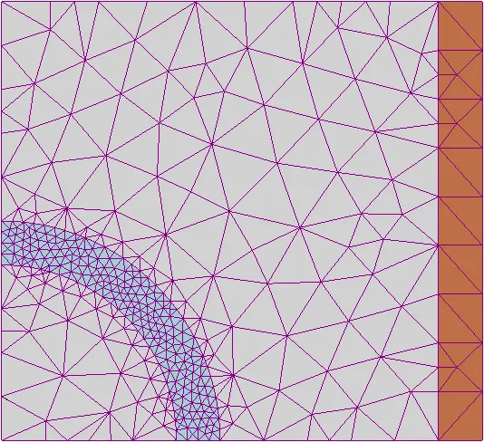
TETRA MESHING:
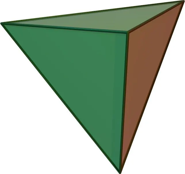
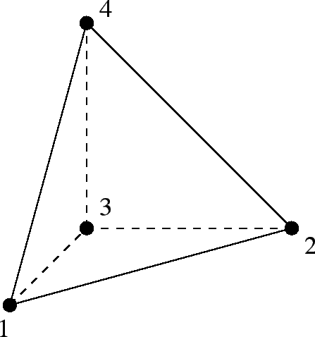
Tetrahedral is a four- nodded solid element which can be generated through the tria element by creating a volume and also through the existing volume of the geometry. These elements are used where the geometry has high thickness and complexity.
TET COLLAPSE:
3D tetra mesh created were checked for Tet collapse (defect generated when the height of tetrahedron 3D element is less than the target element length).
Tet collapse defects were cleared by re meshing the failed elements and changing the height of tetra element by translating nodes. The industries follow the default tet collpase value should be greater than 0.15.
To achieve 3D meshing there is no need to take mid surfacing. Directly the 3d tetra meh is done.
INPUT MODEL:
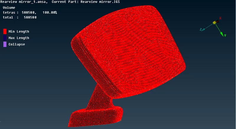
The input model for the tetra mesh is car's inside rear view mirror.
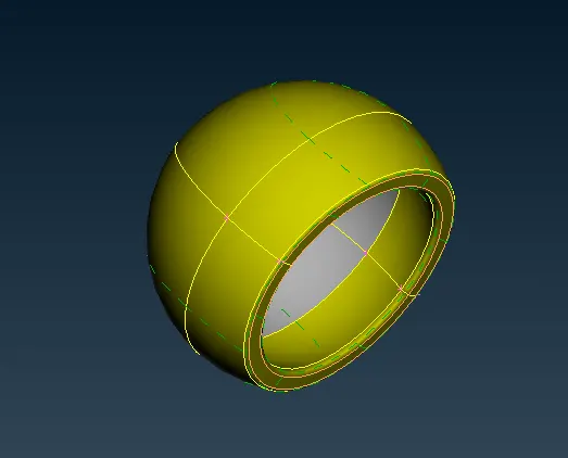
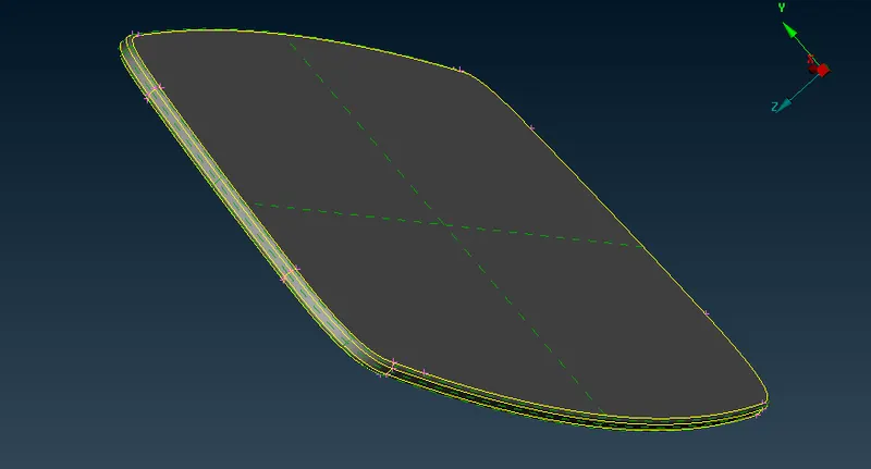
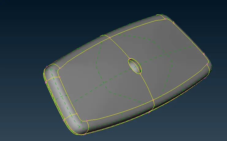
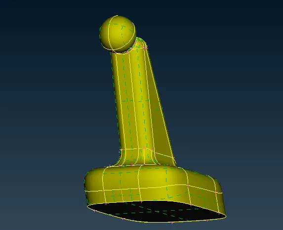
The input model is seperated ito four differenr parts and assigned different properties to it. There is no need of the middle surface for this part because the thickness is more than 5mm.
PROCEDURE:
There are four steps involved in the tetra meshing, they are
Geometry cleanup,
2D shell meshing,
3D tetra meshing,
Checking the quality of the geometry.
Geometry cleanup:
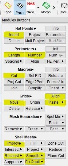
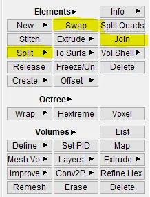
The cleaning of the geometry consists of add/remove hot points, create new surfaces, deleting the existing faces, removing unwanted lines and modifying the geometry of the component to be fitted for the mesh. The following tools aree used for the above operations
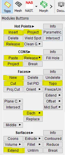
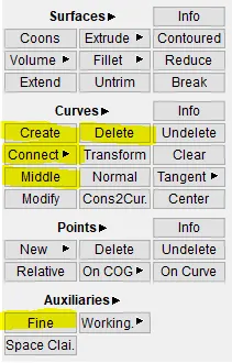
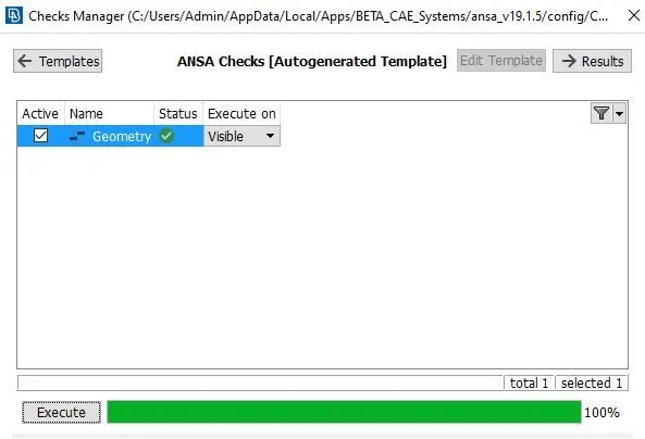
After cleaning the geometry the tool used to check the process is
menubar--->tools--->checks--->geometry.
2D SHELL MESH:
The 2d shell mesh is done from the tools mesh---> mesh generation.
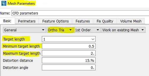
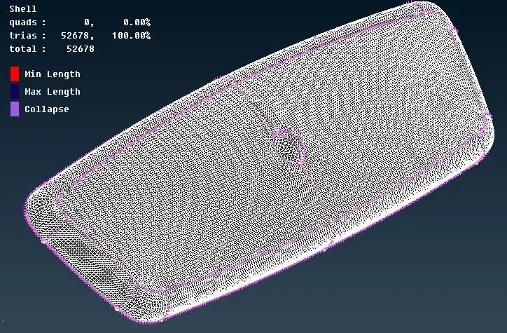
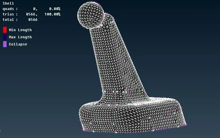
The above figur shows the mesh parametres to be followed on the component. After the 2D shell meshing is done, the mesh edit tools are used to get the better mesh quality. The 2d mesh follows the ortho tria for the curved regions and for other regions of the model is meshed with normal tria elements.
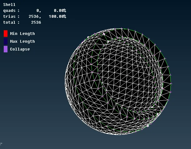
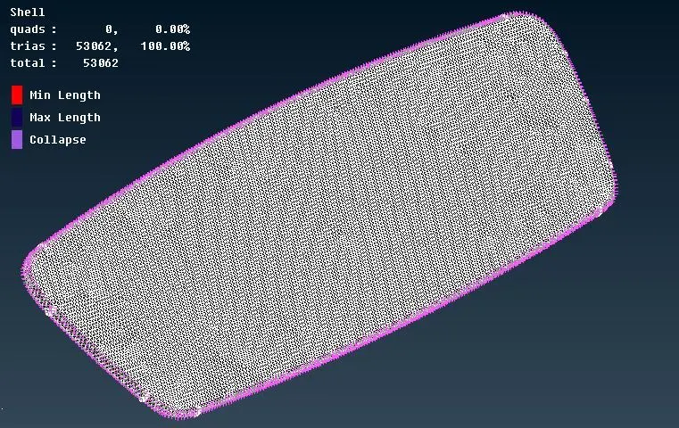
For solid meshing onlt two important criteria is followed for the shell mesh generation they are, minimum element length and maximum element length.
3D TETRA MESHING:
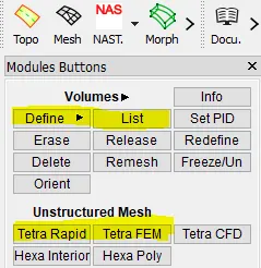
The tetra mesh is done through the tool
volume mesh--->unstructured mesh--->tetra rapid/tetra fem.
Tetra rapid vs tetra fem:
The main difference between Tetra Rapid and Tetra FEM is that in tetra fem mesh the volume mesh follows the certain steps of mesh which we have done on the surface and in tetra rapid mesh it does not follow it and to it rapidly.
After this the model is defined for the volume mesh and it is done from the volume mesh module--->volumes--->define--->manual.
Then the volume is defines as an unmeshed property. Finally the tera mesh is deployed in the component through v-mesh module--->unstructured mesh---?tetra fem/tetra rapid option is used.
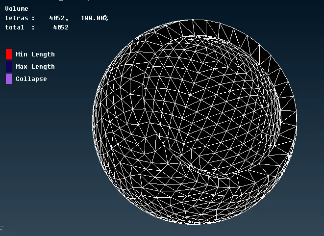
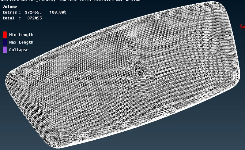
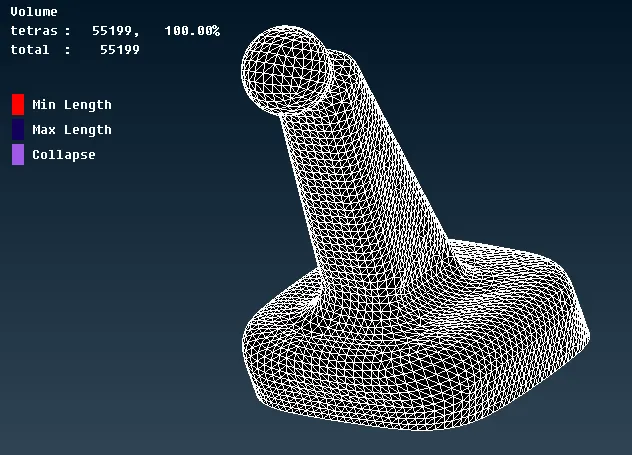
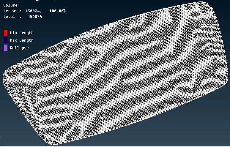
The qulality of the 2d mesh is viewed in the bottom deck hidden option.

The details of all the meshed components are viewed in the database window.
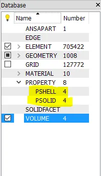
There are four shell components and four solid components saved in the database directory.
CONCLUSION:
The geometry of the model is cleaned and the components are meshed with 2d elements seperately and checked for the quality. After zero errors in the quality the 3d solid meshing is done on the component and checked the quality of the tetra elements.