FRONTAL CRASH TEST ON NEON BIW CAR MODEL USING RADIOSS & HYPERMESH
OBJECTIVE:
To run the frontal crash simulation of a car model and plot the energy differences.
The forces acting on the sections in the selected parts of the model are created and plotted the energy differences.
The displacement forces on the nodes specified in the questions are plotted.
CRASHWORTHINESS:
Crashworthiness is the ability of a structure to protect its occupants during an impact. This is commonly tested when investigating the safety of aircraft and vehicles. Depending on the nature of the impact and the vehicle involved, different criteria are used to determine the crashworthiness of the structure.
It may be assessed either prospectively, using computer models (e.g., LS DYNA, HYPERCRASH) or experiments, or retrospectively by analyzing crash outcomes. Several criteria are used to assess crashworthiness prospectively, including the deformation patterns of the vehicle structure, the accelaration experienced by the vehicle during an impact, and the probability of injury predicted by human body models.
Injury probability is defined using criteria, which are mechanical parameters (e.g., force, acceleration, or deformation) that correlate with injury risk. A common injury criterion is the Head Impact Criterion (HIC).
TYPES OF CRASH TEST:
Frontal Crash Test,
Side Barrier Crash Test,
Side Pool Crash Test,
Rear crash test.
FRONTAL CRASH:
Frontal impact tests is that, Vehicles usually impact a solid concrete wall at a specified speed, but these can also be vehicle impacting vehicle tests.
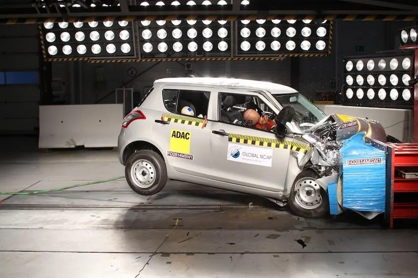
The bumper is directly contacts the rigid wall at the constant speed with the dummy passengers sitting inside the car.
This is done for the three criteria like Head Impact Criteria(HIC),chest decelaration,femur load.
BODY in WHITE(BIW):
Body in white (BIW) is the stage in automobile manufacturing in which a car body's frame has been joined together, that is before painting and before the motor, chassis sub-assemblies, or trim(glass, door locks/handles, seats, upholstery, electronics, etc.) have been integrated into the structure. Assembly involves different techniques such as welding (spot, MIG/MAG), riviting, clinching, bonding and laser brazing.
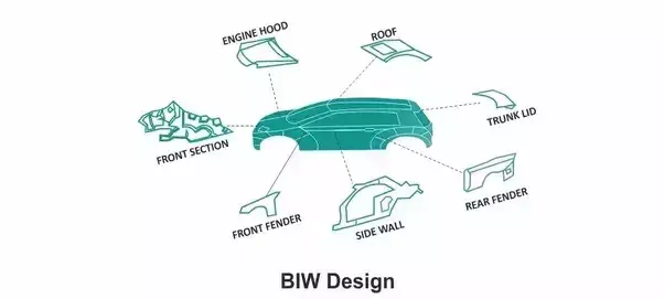
In car design, the BIW phase is where the final contours of the car body are worked out. Extensive computer simulations of crashworthiness, manufacturability, and automotive aerodynamics are required before a clay model from the design studio can be converted into a body in white ready for production.
MODEL SETUP:
The model is added some options to find the exact results of the crash impact, They are;
creating rigidwall,
creating contact interface with crash parametres,
creating initial velocity,
The mass of the whole model is increased to 700kgs and the cog is setup in centre.
The timestep is set to 0.1ms to 0.5ms for the simulation time of 80ms.
RIGID WALL (Rwall):
The rigidwall is the firm wall with the high thickness more than the impacting object. This wall doesn't move with respect to the simulation time and got no results from the simulation. The movement for the all directions are locked only used for the impacting purposes.
The creation of the rigid wall in the hypermesh is done through model--->create rwall.
The rwall is inserted with the coordinate points in x,y,z directions and the normal to the plane is also entered.
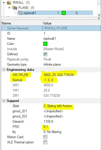
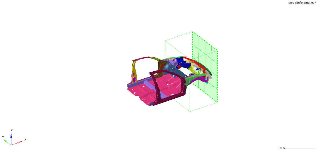
To denote the friction of 0.1, the sliding with friction option is selected and the friction between the rigidwall and the car model is conformed.
The overall length of the rwall should match the total width of the impacting car. There should be always maintain a small gap between the rwall and the model. This is because the plot for the final simulation should starts from zero.
CONTACT INTERFACE:
There is a pre excisting interface is uploaded in the input model and that interface is self contact in nature. The new contact interface is created with the Type7 interface and the crash paramtre values are entered for the simulation.
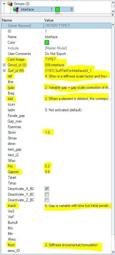
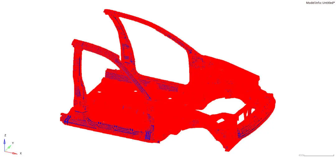
This interface is created for the axial force that is created in the rail and the bumper of the car model.
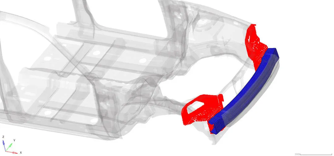
The rail is inputted as the slave node and the bumper system is inputted as master segment in the interface tab. In the bumper it is modelled with both shell and solid elements. The type7 interface is only for the surface to node contact, so the shell and solids doesn't get interacted and the results may cause some errors.
To avoid this the shell surface is only selected for the master segment. The creation of the interface is done through
model--->groups--->Interface--->Type7. This is done because in the final plot of the simulation the Normal force acting in x direction is needed.
INITIAL VELOCITY:
The initial velocity is inputted to see the actual deformation of the car model when impactting the rigidwall.
The initial velocity of 35mph is inputted to the model to hit the rwall. The system takes the value in consistent(kg,mm,ms) unit sysytem. So the mph is converted into mm/ms. The final initial velocity is about 15.64mm/ms.
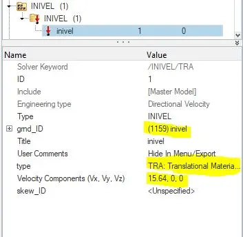
The translational motion is only allowed to the system while impacting. So that only the system calculates the frontal impact crash output in the simulation results.
The initial velocity of 15.64mm/ms is inputted in the x direction(Translational).
The initial velocity is added to all the nodes in the model including rigidbodies and the 1d elements.
MASS ADDITION:
The default mass of the system is about 118kgs and the traget mass of the system is to reach 700kgs. The BIW of the car consists of 27% mass of the total mass of the car. The mass is added to the BIW model to strengthen the model during the impact(considering it as as full car).
According to the Federal Motor Vehicle Safety Standards(FMVSS), the BiW is expected to possess a number of significant properties. It must have high tensile strength as well as high stiffness in bending, torsional, static, and dynamic. It must also provide good quality safety both to the car body and to its occupants against crashes of all kinds of front, rear, side, or even rollover impacts.
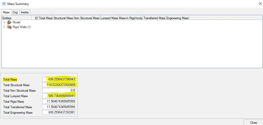
By adding the mass to the system, the COG of the model came to approximate centre. This makes the car to balance the weight on all the sides of the car.
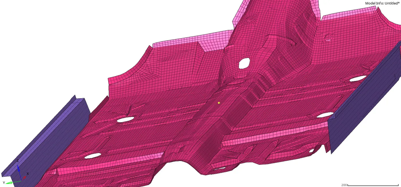
The mass is added in the lower parts of the model and the yellow node indicated in the floorbed of the car model is the COG point.
TIME STEP:
The last step is to setup the time step for the simulation to run. There are many types of time step formulation used in the RADIOSS, and in this case we took only nodal timestep and the interface timestep.
The timestep is mentioned for all the elements in the system and we can choose between the options present in the solver tab in hypermesh.
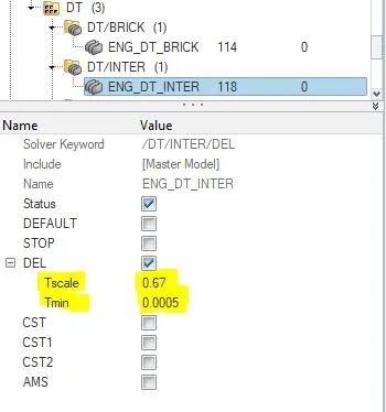
The interface timestep(/DT/INTER) controls the slave nodes during impact and del option is used in this case. This makes the slave nodes to get deleted from the contact interface during the impact within the d_search region and maintains the constant time step
is maintained.
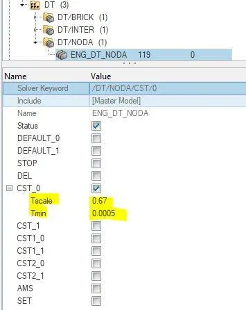
The Nodal timestep(/DT/NODA) controls the nodal impacts during crash and constant time step is maintained by using the default sacle factor of 0.67. This is used when the time step is less than than critical timestep the system adds some mass to the nodes to maintains the constant time step formulation.
QUALITY CHECK:
The quality check is done to maintain the stability in thye system and the time step formulation is the main factor to maintain the stability in the system. If stability increases the accuracy is increased and the simulation is good in nature.
The quality checks like initial penetrations, incompatible kinematic conditions, free nodes in rigid bodies are corrected using the command Tools--->model checker--->Radioss block.
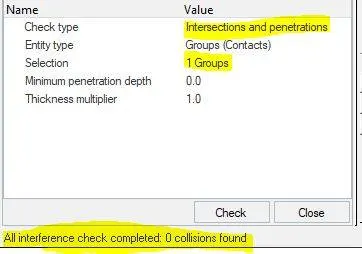
The initial penetration option is used to resolve the initial penetrations within the model before the simulation starts. It ensures the model stability during the simulation.
OUTPUT REQUESTS:
There are six cases are given in this simulation output, they are
- Sectional forces in the rails,
- Apillar cross sectional forces(normal forces),
- Shotgun cross sectional forces(normal forces),
- Axial force received on the rails from bumper,
- Acceleration curve received on the accelerometer at base of B pillar (on B pillar rocker arm),
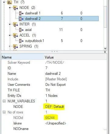
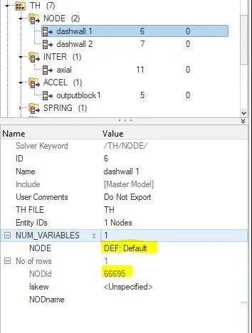
- Intrusions(displacements) on the dash wall 66695,66244.
CROSS SECTIONAL FORCE:
This is used to create a cross sectional area for the group of nodes/elements to observe the forces acting on the area. This is done by creating a local coordinate system with the nodes specified.
For creating a local system, an axis and a plane is created. The local system that we created makes sure of the forces acting normal to the system during the simulation.
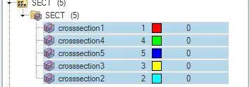
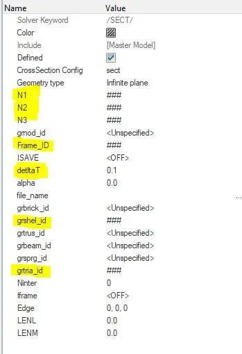
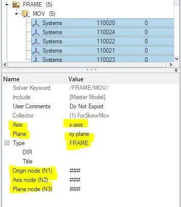
The N1(origin node),N2(axis node),N3(plane node) are local coordinate nodes of the local axis. Here the xy plane is used to create the local axes. The Frame_id is used to input the moving frame that we created. The deltaT is the time step for saving the data and it is given as 0.1. The shell elements and the tria elements are inputted into the cross sectional area.
Cross sectional force in the rails:
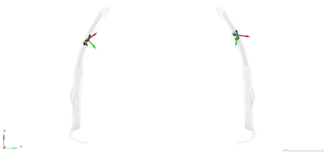
The sectional force acting on the rails are created and the normal force acting to the area is found.
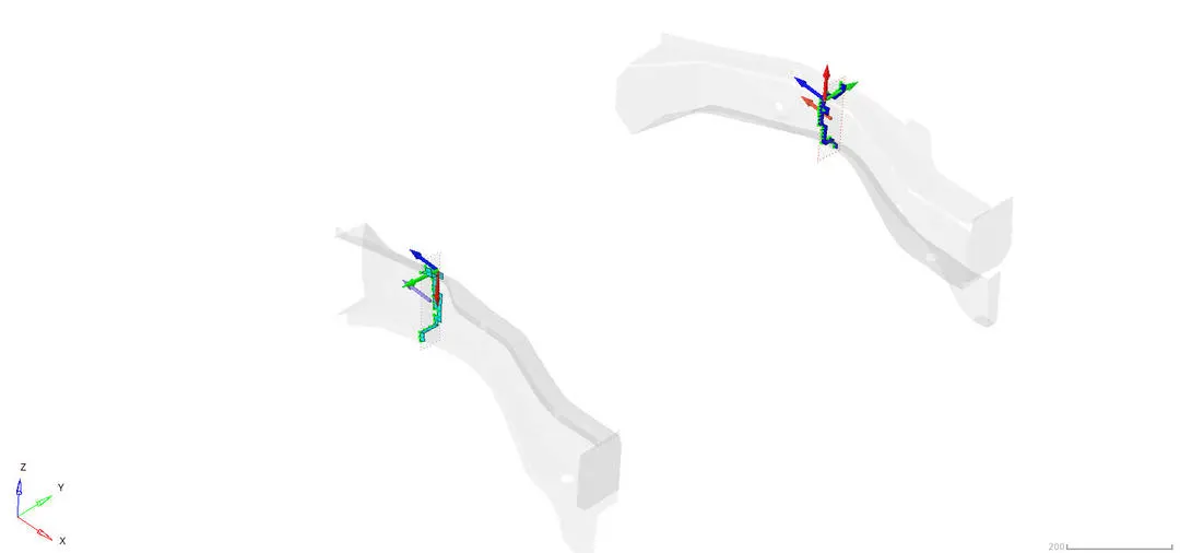
The red arrow denotes the xaxis, the green denotes the yaxis and the blue denotes the z axis. In local system the directions of the coordinate system is changed and the normal force to the section is acting towards the z axis.
A pillar cross sectional forces(normal forces):
The Apillar cross section is created in the xy plane using the moving frame option.
Shotgun cross sectional forces(normal forces):
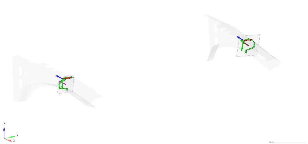
The shotgun's cross sectional area is created in the local coordinate system and the normal force is acting in the z axis of the local system.
Axial force received on the rails from bumper:
The axial force is the force acting towards the axis of the model and it is done through the creation of the interface with the type7 contact.
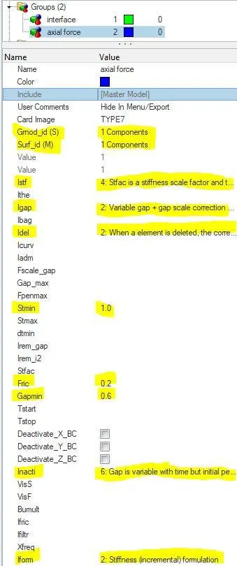
The interface is used because the impact of bumper to the rail is created only through the interface. The type7 is used because it is surface to node contact interface.
The bumper is given as the master segment(blue) and the rails are given as the slave nodes(red).
Acceleration curve received on the accelerometer at base of B pillar:
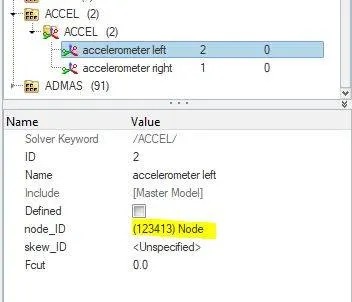
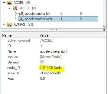
The acceleration data is created at the base of the Bpillar rocker arm on both the sides. The accelorometre sensor senses the acceleration of the vehicle during the impact and also the acceleration of the occupants after the impact. This is done in the global coordinate system.
Intrusions(displacements) on the dash wall 66695,66244.
Intrusion in the specific node is studied in the output simulation.
RESULTS:
To analyse the reults the Hyperview and the Hyperview 2D is used.
Simulation in Hyperview:
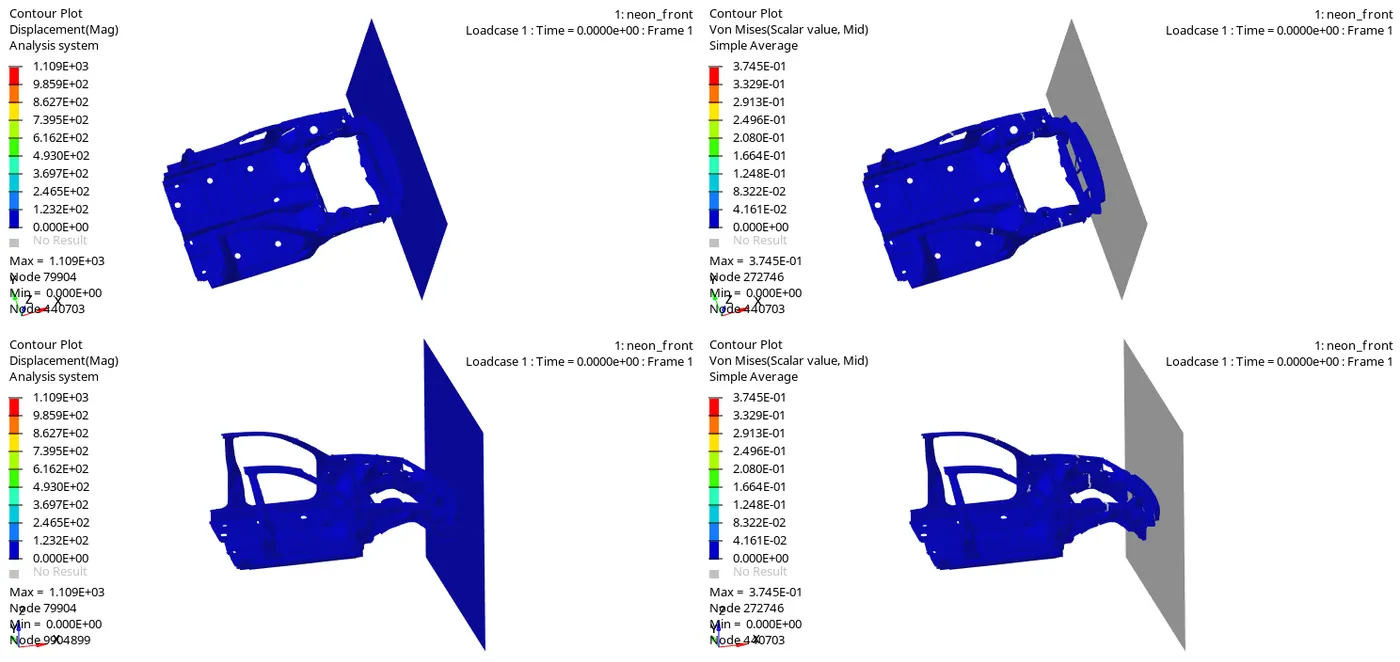
The crash results are viewed and analysed in top, side view. The Vonmises stress and the Displacement are analysed. All the simulations are viewed in a single window for uniform manner. The upper two windows are in top view and the lower two windows are in side view.
EXPLANATION:
In both side view and the top view it is clear that from the beginning of the crash the left side rail, shotgun and the bumper buckled heavily more than the right side of the vehicle symmetrically.
The maximum von mises stress is built up on the rail component on both the sides because the normal force acting against the car motion in the bumper causes it to transfer all its force to the neighbouring component and also the weight of the car during the motion has more impact on the front components of the car.
Plots in Hyperview 2D :
The plots like energy differences, displacements, velocity and the normal forces are analysed.
TOTAL ENERGY OF THE SYSTEM:
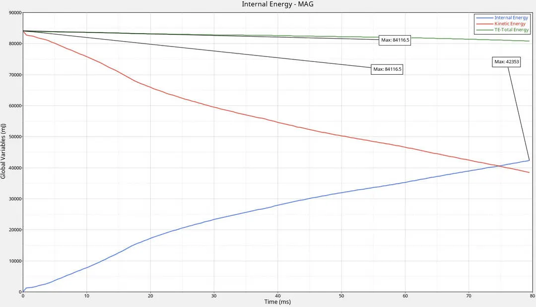
According to the energy plot the kinetic energy decreases with the increase in the internal energy and the total energy remains constant. This shows us that the system is in stable condition.

At last step of the simulation the internal energy is maximum and the kinetic energy is reduced.
Normal force on the rails:
The normal force acting against the motion of the car during the impact is plotted in the local coordinate system.
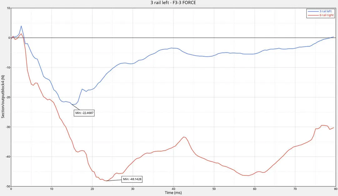
The local zaxis is selected in the local system and the f3(z) force is analysed. At the start of the crash the normal force is not transfered to the rail from the bumper and the peak value is obtained in the negative direction. This is because the force is created in the cross sectional area is opposite to the motion of the car's force.
From the above plot the rail on the left side buckeled quickly than the rail on the right side and max value of force -48.18N
is on the right side rail.
Cross sectional forces on Apillar: 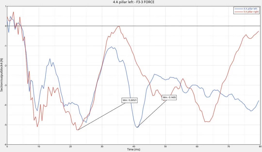 The Apillar is far from the bumper and it is deformed lesser than the frontal components in the crash. The normal force acting in the right side apillar experienced force in less time than the left side apillar.
The normal force in the Apillar comes to zero after the peak acheived because it deformed earlier than the right side components. The max magnitude of the force is on the negative direction because the normal force acting against the actual impacting force of the vehicle.
Cross sectional force in the shotgun:
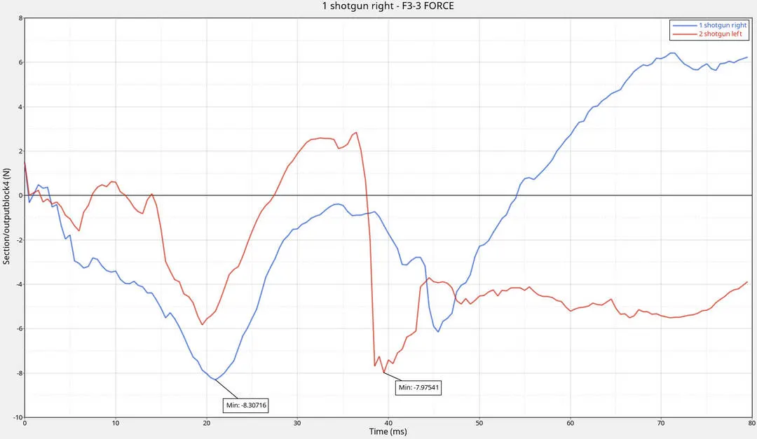
The shotgun is the comkponent located to top of the rail section. The same way of force is acting on the left side of the shotgun resulting it in to deform more than the right side of the shotgun.
The leftside shotgun experiences the less force than the rightside shotgun because the left side of the vehicle hitting the rwall deforms more than the right side of the shotgun.
Axial force recieved on the rails from the bumper:
The bumper is the first component to hit the rigidwall, so it experiences the more deformation/force during the impact. To find the axial force created in the bumper and the rail component is analysed by creating a contact interface with type7 contact.
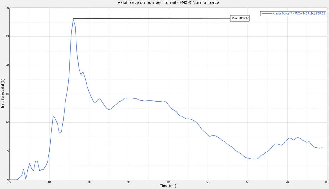
The maximum force experienced in the global x direction is about 28.1287N. The force is maximum when the bumper component is fully crushed and got reduced in magnidude because it buggels in the opposite direction due to the deformation of the rail and shot gun components.
Acceleration curve:
The maximum acceleration of the node specified in the question is analysed by inputting the accelerometre.
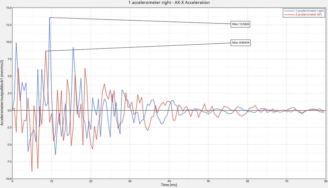
The right side sensor senses more acceleration because it experiences less force than the left side of the vehicle. The sharp wave patterns tells us about the sound wave and the vibration in the vehicle during the crash.
Intrusions:
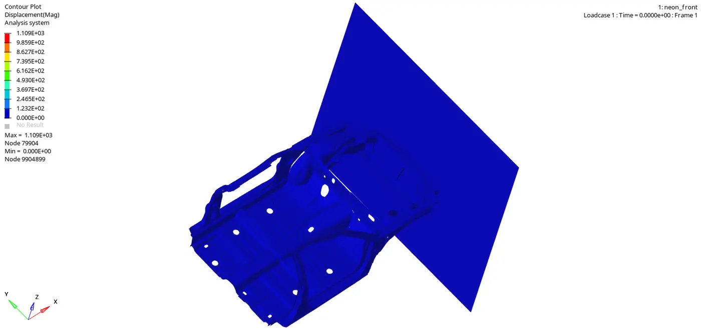
The intrusion of the selected nodes in the dashwall component is simulated using hyperview. The black strip represents the node 66244 and the white strip represents the node 66695.
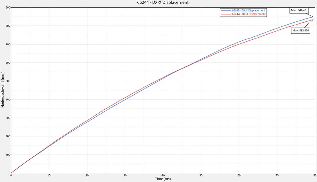 From the starting of the impact the node 66244 displaced slightly more than the node 66695. But from 40ms the intrusion in the dashwall node 66695 increases because the dashwall component surface is subjected some contact with the shotgun and rail component's surface on the left side of the car.
ENERGY ERROR:
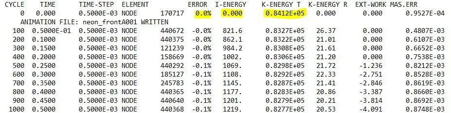

The nodal time step is about 0.5ms and the solver done the calculation correctly.
OBSERVATION FROM THE RESULT:
The simulation results shows that during the crash the left side crushes faster than the right side of the vehicle when contacting with the rigidwall.
The maximum axial force built on the bumper to rail is about 28.1287N. From 15ms onwards the force reduced gradually shows that the normal force against the impact of the car is reduced.
The force that is created on the bumper during impact gets reduced gradually from 28N to 5N. This denotes us when the acceleration of the system reduces the force also gets reduced(Newton's second law).
The energy error is about -2.5% and it is good for the model after crash.
CONCLUSION:
From the simulation I learned about the frontal crash test using the rigidwall barrier with the FMVSS-208 regulation done on the neon BIW model. the intrusion, normal forces, Axial forces all are calculated and analysed in the Radioss solver deck. The crash parametres like initial velocity for the crash, mass of the vehicle body, contact interface parametres all are followed correctly and the results are shown above.