ROOF CRASH ON NEON BIW MODEL USING RADIOSS & HYPERMESH.
OBJECTIVE:
To run the roof crash test simulation of a neon BIW car model and plot the energy differences.
The maximum force vs displacement peak in curve is to plotted for the impactor.
The load path after the impact is studied.
CRASHWORTHINESS:
Crashworthiness is the ability of a structure to protect its occupants during an impact. This is commonly tested when investigating the safety of aircraft and vehicles. Depending on the nature of the impact and the vehicle involved, different criteria are used to determine the crashworthiness of the structure.
It may be assessed either prospectively, using computer models (e.g., LS DYNA, HYPERCRASH) or experiments, or retrospectively by analyzing crash outcomes. Several criteria are used to assess crashworthiness prospectively, including the deformation patterns of the vehicle structure, the accelaration experienced by the vehicle during an impact, and the probability of injury predicted by human body models.
Injury probability is defined using criteria, which are mechanical parameters (e.g., force, acceleration, or deformation) that correlate with injury risk. A common injury criterion is the Head Impact Criterion (HIC).
TYPES OF CRASH TEST:
Frontal Crash Test,
Side Barrier Crash Test,
Roof Crash Test,
Side Pool Crash Test,
Rear crash test.
ROOF CRASH:
The main advantage of doing the roof crash is to see the determine whether there was a statistically significant relationship between the maximum severity of head,neck, and face injuries due to occupant roof contact that occurred in rollovers that were likely tobe covered by Federal Motor Vehicle Safety Standard No. 216.
FMVSS 216, Roof Crush Resistance, establishes strength requirements for the passenger compartment roof of passenger cars, multipurpose passenger vehicles, trucks and buses with a GVWR of 2722 kilograms or less.
The purpose of the standard is to reduce deaths and injuries due to the crushing of the roof into the passengercompartment in rollover accidents.
This test is not recommended for the convertibles, the scholl buses and trucks.
IMPACTOR:
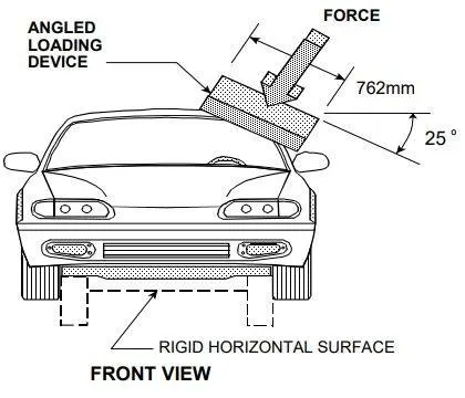
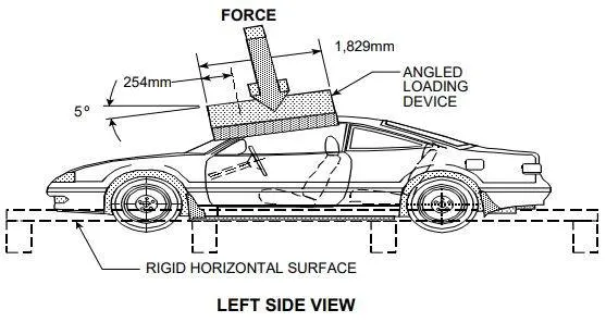
The impactor acts as a static loading device for the crash test. It is a rectangular block having a dimension of 762mm*1829mm from the FMVSS No.216.


The inputted load device is in the same dimension mentioned above. The impactor is setted in an angle so that it crushes the roof correctly in the simulation.
BODY in WHITE(BIW):
Body in white (BIW) is the stage in automobile manufacturing in which a car body's frame has been joined together, that is before painting and before the motor, chassis sub-assemblies, or trim(glass, door locks/handles, seats, upholstery, electronics, etc.) have been integrated into the structure. Assembly involves different techniques such as welding (spot, MIG/MAG), riviting, clinching, bonding and laser brazing.
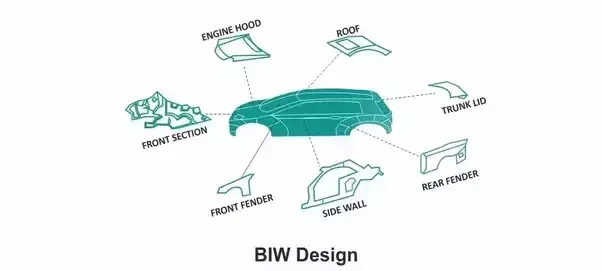
In car design, the BIW phase is where the final contours of the car body are worked out. Extensive computer simulations of crashworthiness, manufacturability, and automotive aerodynamics are required before a clay model from the design studio can be converted into a body in white ready for production.
MODEL ETUP:
The model for the roof crash is done on the Neon BIW car model and the following parametres are set up.
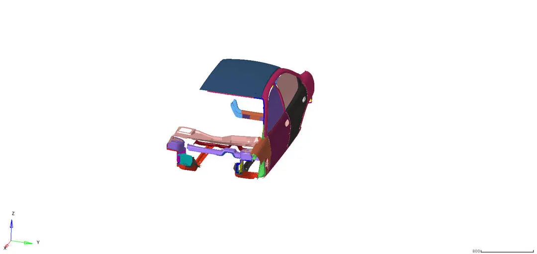
Placing the impactor on the edge of the roof,
Creating interface for the vehicle and the impactor,
Creating the boundary conditions for the suspension lock,
Creating a boundary condition for the free end of the spring in the impactor,
Creating a boundary condition for the the master node of the impactor's rigid body,
Creating a imposed displacement for the impactor.
Placing the impactor on the edge of the roof:
The impactor is the static loading device used to crush the vehicle from the roof to see how the occupants headroom behaving while the impact done.
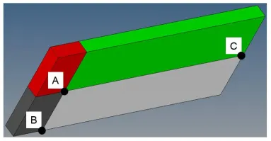
This is the given impactor model for the crash test. This part is placed on the top edge of the vehicle's roof.
This is done in the HYPERMESH using the command
Tools--->translate option,
Tools--->rotate option.
The translation of the whole part in global X,Y,Z axis in both positive and the negative direction.

The rotation of the whole impactor is done in two ways;
A 180° rotation about the global z-axis with the point opposite to C as base point,
A 5° rotation about the axis through axis AB,
A 25° rotation about the axis through axis AC.

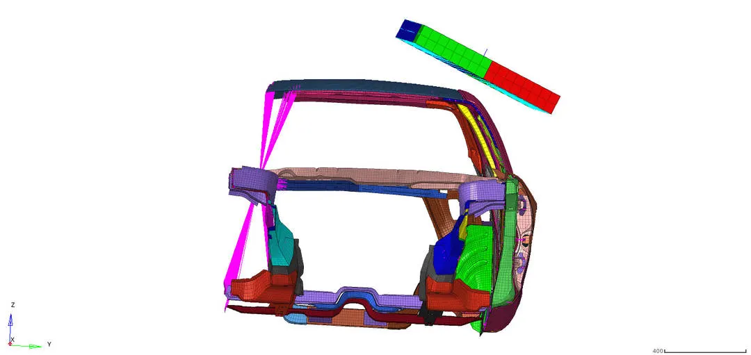
After completing this steps the impactor is placed with some gap above the top edge of the vehicle roof.
Creating Interface:
The interface is the mandotary step followed to see the how the elements are behaving while the crash happens.
The interface is created for both the car and the impactor. The Type7 contact interface is created for both the cases and the crash parametres for the type7 contact is followed.
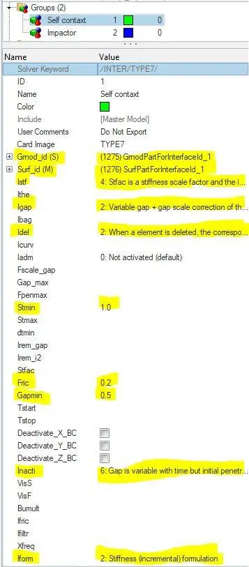
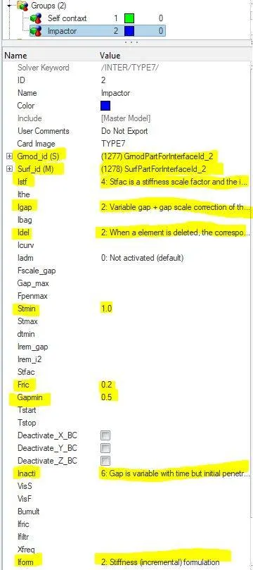
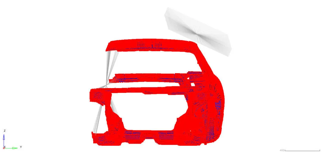
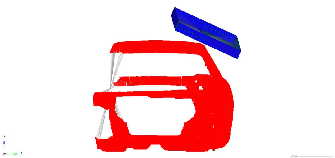
For the contact interface master and the slave selection of the vehicle the spring componens, rigidbodies and the 1d elements are not selected.
Creating boundary conditions for the suspension lock:
The boundary condition is used to lock the degree of freedom of the components and this leads to the accurate simulation results for the crash test.
The main use of the suspension locking is to prevent the sliding of the vehicle while the crash is occuring.
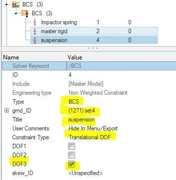
The translational DOF for the Z axis is locked.
Creating a boundary condition for the free end of the spring in the impactor:
The free end of the master spring is locked to prevent from instablity in the model during the simulation.
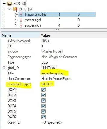
Creating a boundary condition for the the master node of the impactor's rigid body:
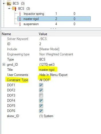
The Creation of a BCS collector to guide the master node of the impactor rigid body so that it is free to translate normal to the face of the impactor, but is fixed in all other DOFs.
Creating a imposed displacement for the impactor:
The imposed displacement is the term used to achieve continous motion of the selected component through the time independent of the other parametres.
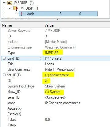
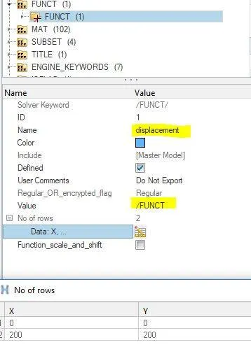
The imposed displacement is setup with the function of table with two rows having starting and ending of the displacement values.
Time step:
All the engine card definitions are created for the simulation. This helps printing the .rad file, .out file and the .rst file too.
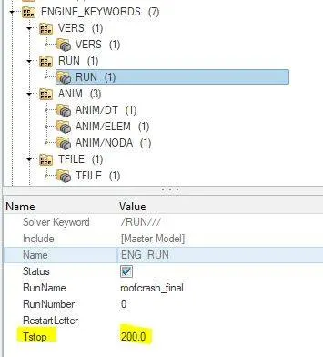
The Engine/RUN command is used to setup entire run for the crash simulation. The total simulation time is about 120ms.
The Anim/DT is used to set up to write animation files (A-files) at a time frequency equal to Tfreq. The Tfreq is about 5ms.
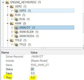
The Anim/ELEM is used to print the element types to appear on the .out file of the simulation. The following element types are printed in the simulation results, they are,
Elemental Energy,
Elemental equivalent plastic strain,
Elemental hourglass energy,
Elemental von Mises stress,
Nodal added mass.
The Anim/NODA is used to generates animation files containing nodal scalar data.
The /Tfile is used to define the frequency of writing the time history file of T-file. The time frequency is about 0.1ms.
The DT/NODA is used to activates the nodal time step control method with the option to apply mass scaling to increase a model’s time step. The min time step is about 0.0005ms.
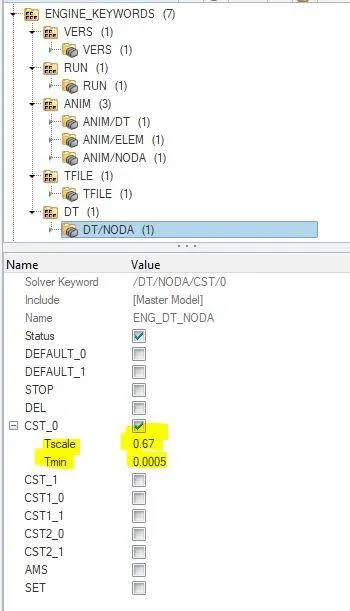
The scale factor for the time step calculation is about 0.67. This is done to maintain the constant time step all over the simulation.
Creating connectivity:
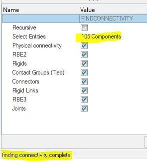
The connectivity is the important term defined in the car's model that holds all the components together during the crash. Without connectivity the components are scattered during the crash making some errors in the simulation output.

OUTPUT REQUEST:
The output of the simulation is analysed and the plots are studied and compared the results with the acutal results from the standards.
Final simulation:
The von mises stress and the displacement of the car and the impactor is simulated in the final simulation.
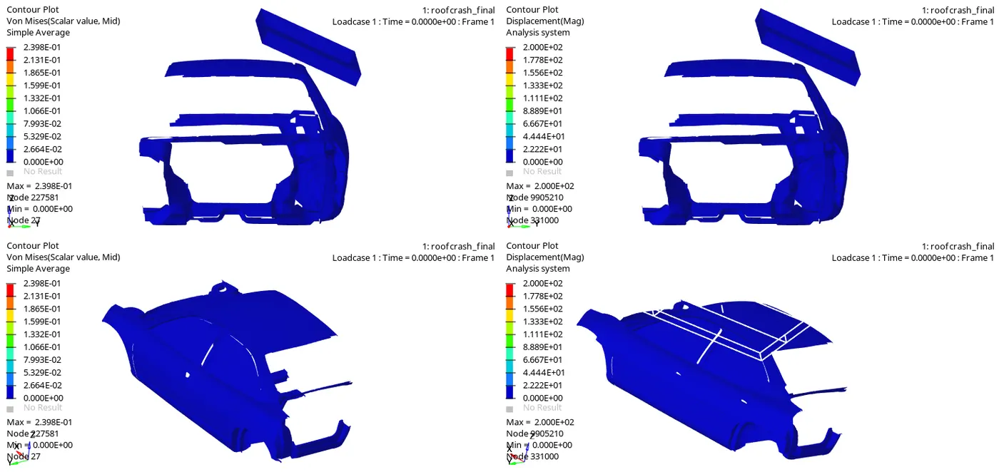
When the impactor hits the roof, the component deforms and due to imposed displacement of the impactor the vehicle is cruhed for 200ms.
The impactor is rigid in nature so the stress value is almost zero in this case.
According to the FMVSS rule No.216 the maximum displacement is occured on the impactor and it is shown in the simulation results.
From this the head injury criteria, neck injuries, spine and thorax injuries are taken into account for the occupants ultimate safety.
Plot Results:
There are two plot results are to be discussed in this cases, they are energy differences and the force vs displacement of the impactor and the vehicle after the crash.
Total energy plot:
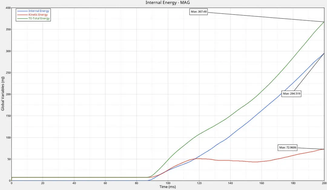
From the start of the simulation, all the energies are in zero state but after 80ms(impactor hits the roof) the internal energy of the vehicle increases with the decrease in kinetic energy and the total energy remains constant till the end of the simulation.
Force vs Dispalcement:
The force vs displacement curve is used to determine whether the vehicle resistive force withstand the imapctor's crush force.
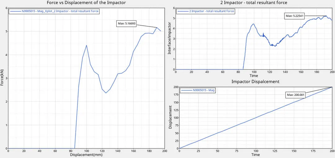
The left side big plot refers to the cross plot made for the force vs displacement of the impactor. The two plots on the right side is the seperate force and displacement of the impactor. The maximum force is about 5.166kN.
ENERGY ERROR:
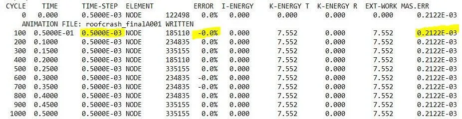
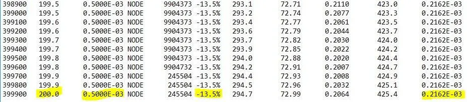
The energy error is almost negative in this case this denotes that the hourglass effect taken place into this analysis. The maximum energy error is about -13.5%.
JUSTIFICATION:
The resistance force is calculated by the expression below;

where;
F_res= resistive force(kN),
GVWR=Gross vehicle Weight ratio(kN).
The 2.5 is taken because the total mass of the vehicle is less than 2000kg's(FMVSS rule No. 216),and the neon BIw car model obtains only 175kgs. The target load is less than the criteria, so the 2.5 value is taken.
The GVWR is obtained by multiplying the gravity and the total mass of the vehicle.so,
GVWR=0.0098*175
GVWR=1.715kN
According to FMVSS 216, the Target load of the vehicle should be about 47kN. But in our case the target load of the vehicle is1.715kN. The resistive force of the roof is calculated by,
F_res=2.5*1.715
F_res=4.2875kN
The target load we obtained from the force vs displacement curve is about 5.15kN. So the model is failed in the test because the actual load that we obtained is more than the target load results.
The another criteria is also analysed, that is Strength to Weight Ratio(SWR). It is calculated by
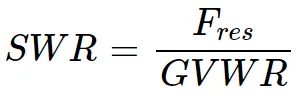
SWR=5.16/1.715
SWR=3.00
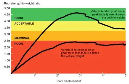
This simply assigns a rating of Good(SWR greater than 4.0), Acceptable (SWR greater than 3.25 and up to 4.0), Marginal (SWR greaterthan 2.5 and up to 3.25) or Poor (SWR less than 2.5). For us the model obtained the SWR of 3.0.
RESULT:
The roof crash for the crash parametres given and the maximum force, dispalcement and the energy differences of the Neon BIW car model is analysed.