Week 4- Challenge
OBJECTIVE:
The main objective of this study is to create a 1D elements on the given component with given cross section and Degree of Freedom(DOF).
For that component given the geometry is cleaned, taking midsurface and meshed with the userdefined criteria.
ID ELEMENTS:
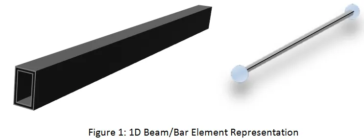
All line elements, whether straight or curved, are called 1D element in which they have translational and rotational displacement functions. 1D element are truss,rod and beam element.
Procedure:
There are several steps involved in this study, they are
Auto cleanup geometry,
Midsurfacing
Meshing,
Creating Rigid links,
Creating 1D elements,
Creating cross sections for 1D elements,
Add masses to the 1D elements links,
Creating spring elements to connect two components.
auto cleanup geometry:
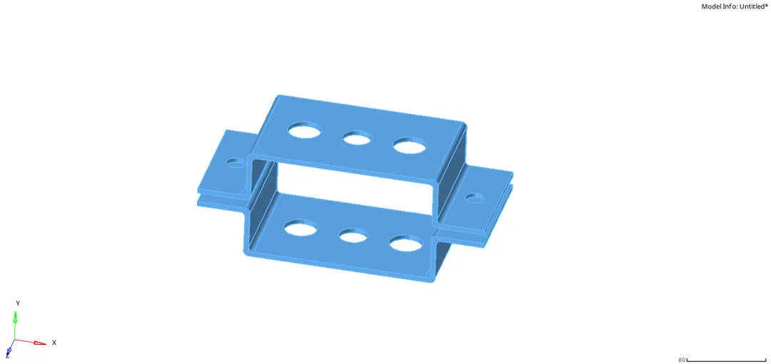
The auto cleanup is the mandatory option carried out in the Hypermesh to encounter geometry errors in the model. This is done through the command Geometry--->auto cleanup--->selecting surfaces--->autocleanup.

Midsurfacing:
Then the component is subjected to midsurfacing process where a new middle surface is created between two surfaces of the component selected. Then the original component's surface is deleted. This is done through the command
Geometry--->midsurface--->surfs--->extract.
There is an another option used to create an accurate middle surface. This is because when we use a default option to extract the surafce, there are some geometrical errors created in the new surface. To avoid this offset potion is used in the midsurface tab. this is done through the command geometry--->automesh--->extraction option--->offset option--->extract.

offsetting:
Create pieces of the middle surface by offsetting the model's side surfaces towards the middle. This is the traditional approach for midsurfacing in HyperMesh.
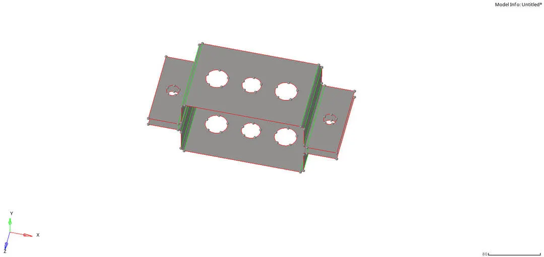
Then the two midsurfaces are seperated and added in the new component using the command
Tools--->organise--->select surface--->destination component.
Meshing:
The meshing is used to create a 1d element in the component.Without the help of nodes and elements the 1D elements are not created. The meshing is done through 2D--->automesh--->surface--->automesh.
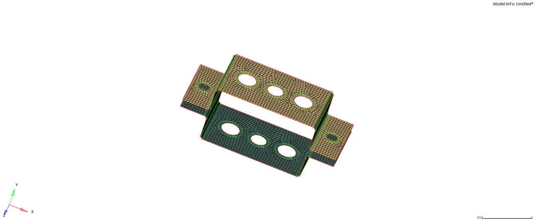
The quality of the components are checked using 2D--->quality index.
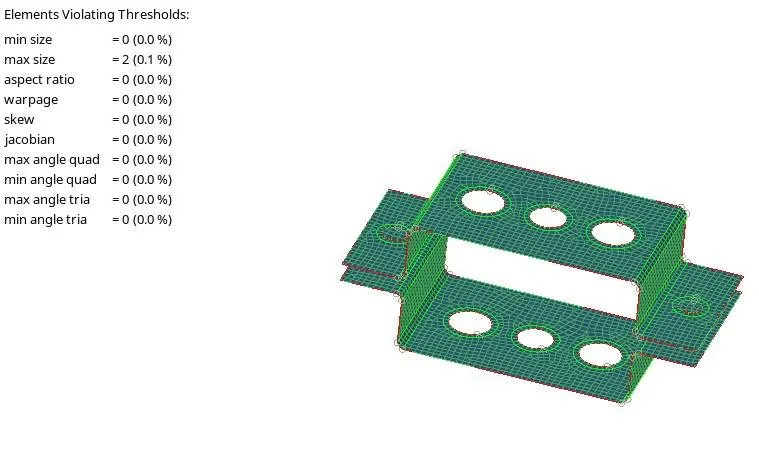
Both components surfaces are green in colour shows us that the quality of the system is perfect.
Creating Rigid links:
The rigids are used to connect the component to using links that helps in making the system more stiffer. There are two links used to create the links in the model, They are
Rbe2 link: used for infinite stiffness for the nodes(doesn;t move at all).
Rbe3 link: used to create nodes that can move on both translational and rotational motion based on load path.
The rigids can be created using the command 1D--->Rigids--->create--->select master/slave node--->element type--->selecting dof--->create.

The rigids can be created using the command 1D--->Rbe3--->create--->select master/slave node--->
element type--->selecting dof--->create.

For selecting the constraints for the dof it is mentioned in the question given, they are
Rod element with only translational DOF and RBE2 link,
Beam element with all DOF and RBE3 link,
Bar element with only x and y DOFs With RBE3 link.
The selection of master and slave node is calculated by using calculated node and multiple node in the toggle box respectively.
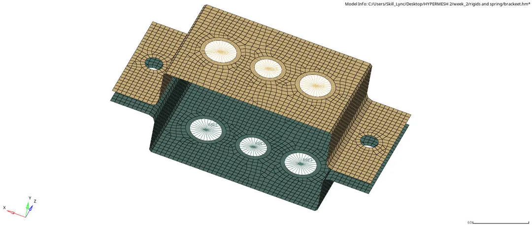
The links in the upper surfaces are associated with its parent component and the links in the below surfaces are associated with its parent component.
Creating 1D elements:
According to the question we should have to create bar, rod, beam elements.
Bar element: 1D elements created in a space between two or three nodes of a model where beam properties are desired.1D (1st order) elements with 2 nodes used to model axial, bending, and torsion behavior. The command to create bar element is 1D--->bars--->nodes--->orinetation--->element type--->create.

By using bar option we can create both bar and beam element. The property and the type of element is changed according to the requirement. The orientation potion is used to know haow the bar element is behaving in the 3d space.
Rod element: A rod element is an element created in a space between two nodes of a model where rod properties are desired. The two nodes are related to each other based on the properties of the rod element connecting them. Rod elements are displayed as a line between two nodes with ROD written at the centroid of the element.
In this element creation the orientation of the element is not required to create just selecting the two nodes and create a rod element. The element type and the property for the element is assigned according to the requirements.
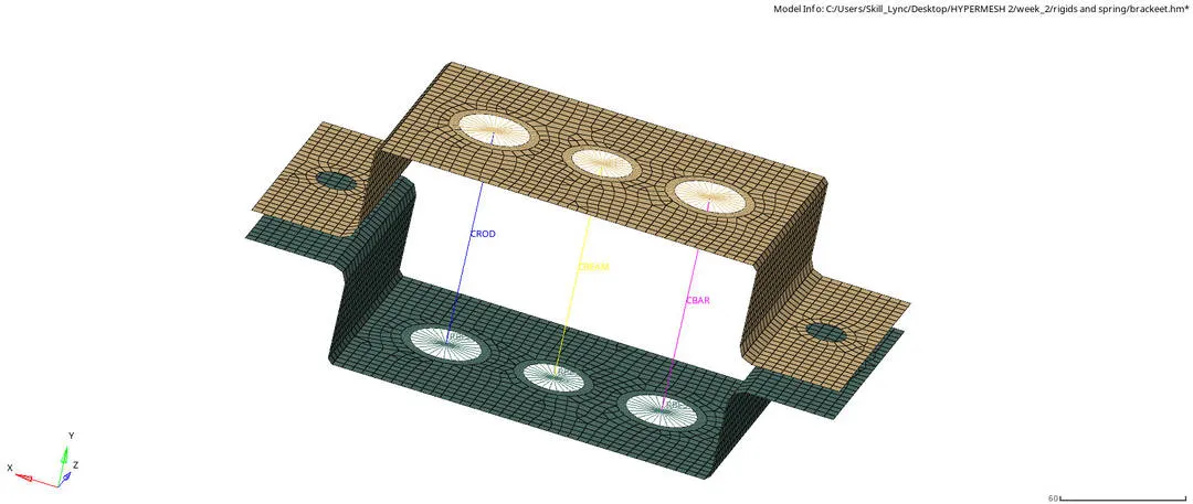
Each and every 1D element is assigned a different property and material chracteristics and saved as a component.
Creating cross sections for 1D elements:
The main advantage of creating a beam cross-section entities that you can use to simplify complex portions of your model into simple bar elements. The cross section is created using the Hyperbeam option.

There are predefined library for the simple cross section images saved in the hypermesh. There are many options to create a cross section and we can use a standard section panel to create a cross sections.
The Standard Section subpanel used to quickly generate models using a few standard shapes such as boxes or tubes. HyperBeam uses the closed-form equations for their section properties. In our question we are subjected to create athree cross sections for the rod, bar and the beam elements.
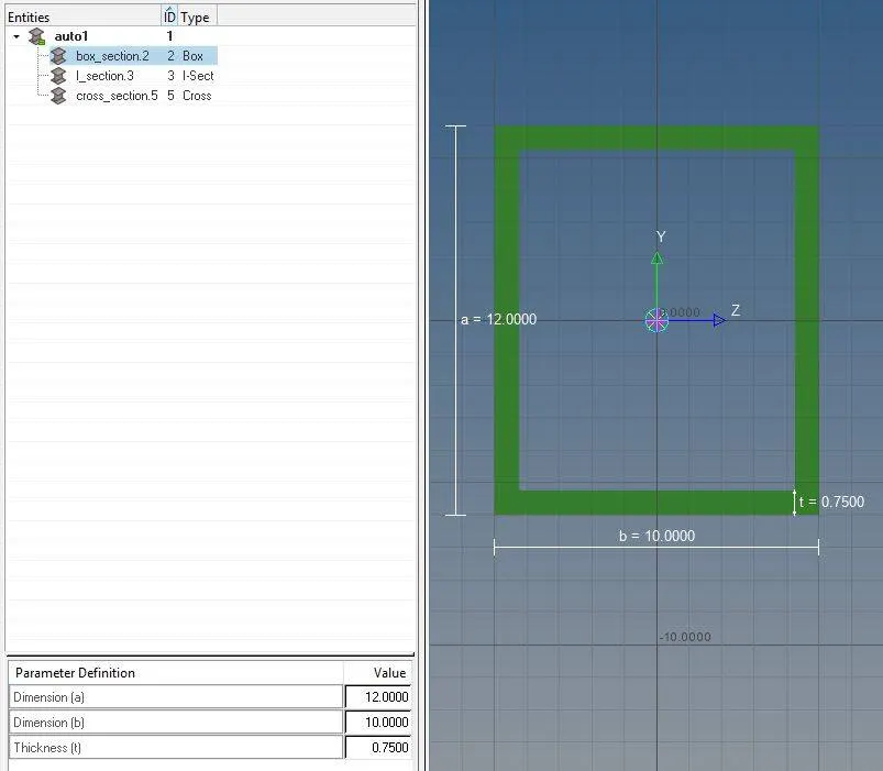
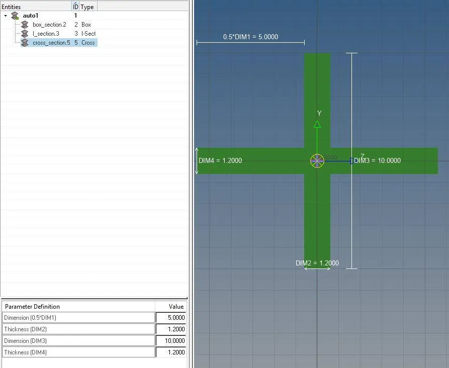
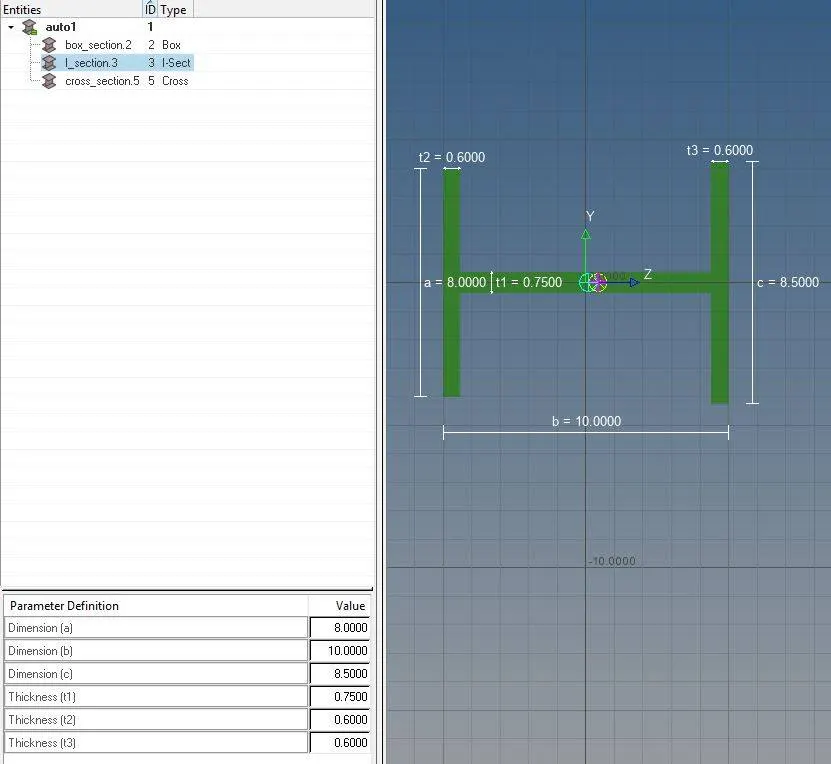
Rod element cross section Bar element cross section Beam element cross section
After creating a cross section the property card is created for each element and assign the cross section to the respected 1D element in the browser tree. The property card is created in the browser tree tab.
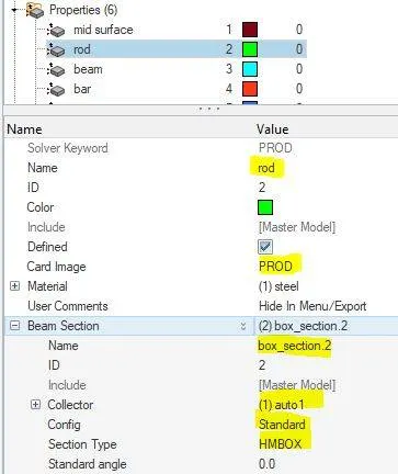
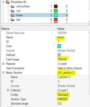
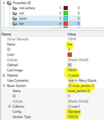
Then the updation is done through 1D--->bars--->update--->select elems--->property--->update. for both the bar and the beam elements.
The updation of rod element is done through 1D--->rod--->update--->select elems--->property--->update.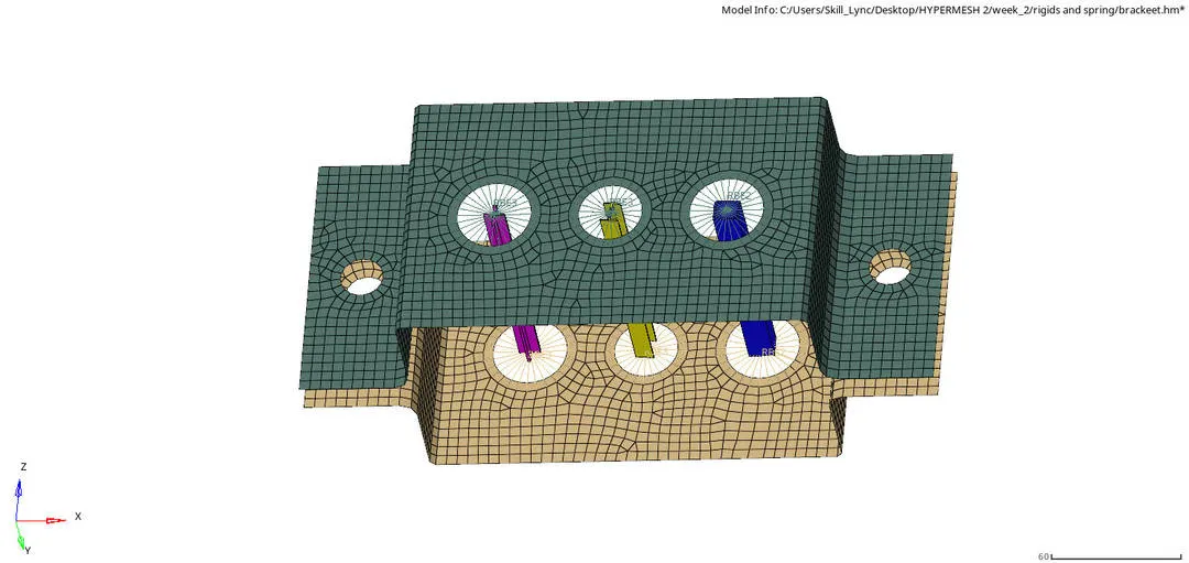
Add masses to the 1D elements links:
Use the Masses panel to create mass elements. A mass element rests on a node and is used to represent mass. Mass elements are displayed as a dot with the letter M written at the centroid of the element. The magnitude of 10 is added to the node on both the component and the property, element type is also assigned.

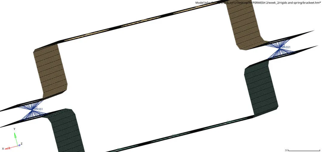
The common Rbe2 link is used to create and connectes the two components and then only the mass is added to that common master node.
Creating spring elements to connect two components:
Use the Springs panel to create spring elements. A spring element is an element created in a space between two nodes of a model where a spring connection is desired. Spring elements are displayed as a line between two nodes with the letter K written at the centroid of the element.
The command to add the spring element to the component is through 1D--->springs--->nodes--->
property--->element type selection--->magnitude--->create.

The property is assigned to the spring element and inputted it in the spring tab.
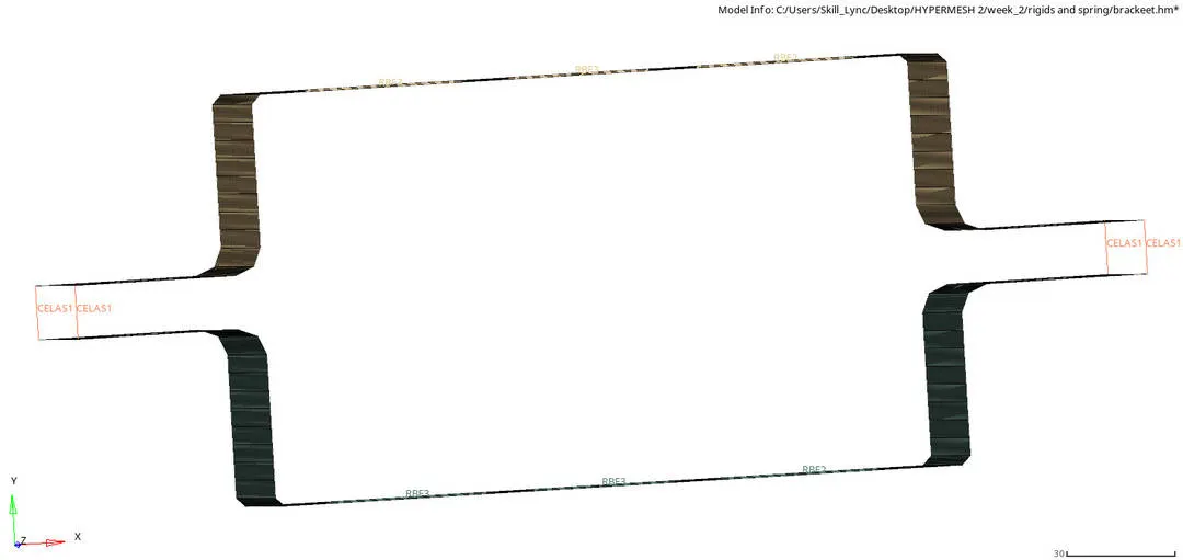
2D REPRESENTATION OF THE MODEL:
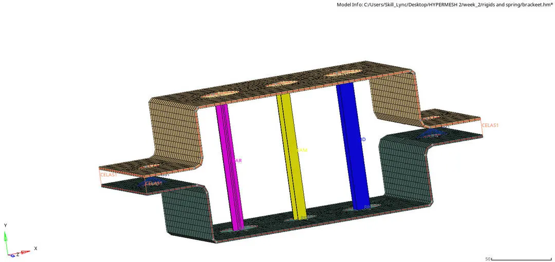
RESULTS:
The 1D elements are created and the cross section is assigned to that 1D elements. The quality criteria of the component is checked and the mid surafce is created.