Crash test on Neopn BIW Car Model using Radioss & Hypermesh
OBJECTIVES:
The main objective of this assignment is to see the results of the side pole crash test. For that the input crash parametres are inputted according to the Federal Motor Vehicle Safety Standards(FMVSS) rule number214.
The normal force acting against the impact are studied by creating a cross sectional area in a selected components.
The intrusion are studied by selecting the nodes in the Bpillar, hinge, fuel tank region(approx).
CRASHWORTHINESS:
Crashworthiness is the ability of a structure to protect its occupants during an impact. This is commonly tested when investigating the safety of aircraft and vehicles. Depending on the nature of the impact and the vehicle involved, different criteria are used to determine the crashworthiness of the structure.
It may be assessed either prospectively, using computer models (e.g., LS DYNA, HYPERCRASH) or experiments, or retrospectively by analyzing crash outcomes. Several criteria are used to assess crashworthiness prospectively, including the deformation patterns of the vehicle structure, the accelaration experienced by the vehicle during an impact, and the probability of injury predicted by human body models.
Injury probability is defined using criteria, which are mechanical parameters (e.g., force, acceleration, or deformation) that correlate with injury risk. A common injury criterion is the Head Impact Criterion (HIC).
TYPES OF CRASH TEST:
Frontal Crash Test,
Side Barrier Crash Test,
Side Pole Crash Test,
Rear crash test.
SIDE POLE CRASH TEST:
The main reason to conduct this type of crash is to study the occupants head Impact Criteria(HIC) and the intrusions in the underbody structures.
There are two types of side pole test are conducted,they are;
Side pole crash test at 90degree,
Side pole crash test at 75degree.
The 90 and 75 degree both denotes the impact line of the pole towards the Bpillar of the vehicle(side view).
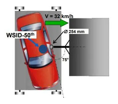
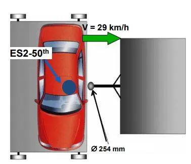
Both of the types have different input crash criteria. At 90degree crash the car impacts the pole at the speed of 32kmph and for the 75degree crash the car impacts the pole at the speed of 29kmph. The diametre of the side pole is 254mm and it is constant for both the types of impact.
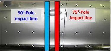
The dummies used on both the tests are different. The 75degree pole test is also known as oblique side pole crash test. For oblique pole crash the vehicle is offsetted 15degree in zaxis at counter clockwise direction of the global axis.
BODY in WHITE(BIW):
Body in white (BIW) is the stage in automobile manufacturing in which a car body's frame has been joined together, that is before painting and before the motor, chassis sub-assemblies, or trim(glass, door locks/handles, seats, upholstery, electronics, etc.) have been integrated into the structure. Assembly involves different techniques such as welding (spot, MIG/MAG), riviting, clinching, bonding and laser brazing.
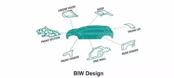
In car design, the BIW phase is where the final contours of the car body are worked out. Extensive computer simulations of crashworthiness, manufacturability, and automotive aerodynamics are required before a clay model from the design studio can be converted into a body in white ready for production.
MODEL SETUP:
There are two model setup done,they are;
90degree sidepole crash test,
75degree sidepole crash test.
The model is added some options to find the exact results of the crash impact, They are;
creating rigid pole,
creating contact interface with crash parametres,
creating initial velocity,
The mass of the whole model is increased to 700kgs and the cog is setup in centre.
The timestep is set to 0.1ms to 0.5ms for the simulation time of 80ms.
The model setup is same for both the models but the output requests are changed.
90DEGREE SIDEPOLE CRASH TEST:
creating Rigid pole:
The rigidpole is the firm ploe with the stiffness more than the impacting object. This wall doesn't move with respect to the simulation time and got no results from the simulation. The movement for the all directions are locked only used for the impacting purposes.
The creation of the rigid wall in the hypermesh is done through model--->create rwall--->Cylinder.
The rwall is inserted with the coordinate points in x,y,z directions and the normal to the plane is also entered.
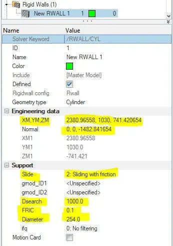
To denote the friction of 0.1, the sliding with friction option is selected and the friction between the rigidpole and the car model is conformed.
There should be always maintain a small gap between the rwall and the model. This is because the plot for the final simulation should starts from zero.
For side impact the translational motion in the yaxis is selected.
Contact interface:
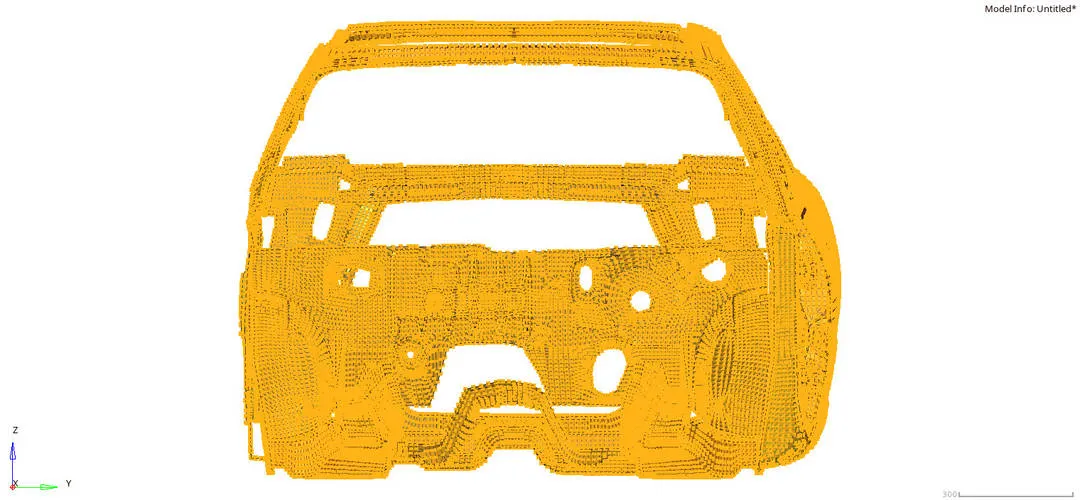
There is a pre excisting interface is uploaded in the input model and that interface is self contact in nature and with the crash parametre values are entered for the simulation.
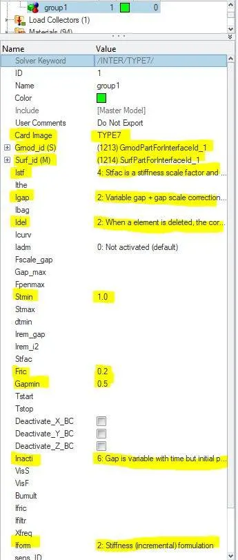
Several friction formulations are available within Radioss. The simplest one, which is also the most used, is the Coulomb friction law. This formulation provides accurate results in crash analysis and requires just one parameter (Coulomb friction coefficient, μ">μ ). The default value for μ">μ is 0 (no friction between surfaces).
Initial Velocity:
The initial velocity is inputted to see the actual deformation of the car model when impactting the rigidwall.
The initial velocity of 35mph is inputted to the model to hit the rwall. The system takes the value in consistent(kg,mm,ms) unit sysytem. So the mph is converted into mm/ms. The final initial velocity is about 15.64mm/ms.
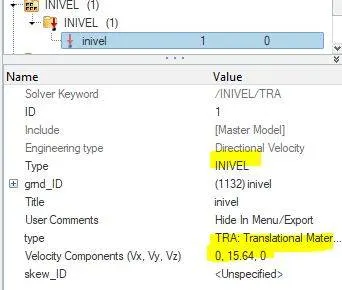
The translational motion is only allowed to the system while impacting. So that only the system calculates the side pole impact crash output in the simulation results.
The initial velocity of 15.64mm/ms is inputted in the y direction(Translational).
The initial velocity is added to all the nodes in the model including rigidbodies and the 1d elements.
Mass Addition:
The default mass of the system is about 119kgs and the traget mass of the system is to reach 700kgs. The BIW of the car consists of 27% mass of the total mass of the car. The mass is added to the BIW model to strengthen the model during the impact(considering it as as full car).
According to the Federal Motor Vehicle Safety Standards(FMVSS), the BiW is expected to possess a number of significant properties. It must have high tensile strength as well as high stiffness in bending, torsional, static, and dynamic. It must also provide good quality safety both to the car body and to its occupants against crashes of all kinds of front, rear, side, or even rollover impacts.
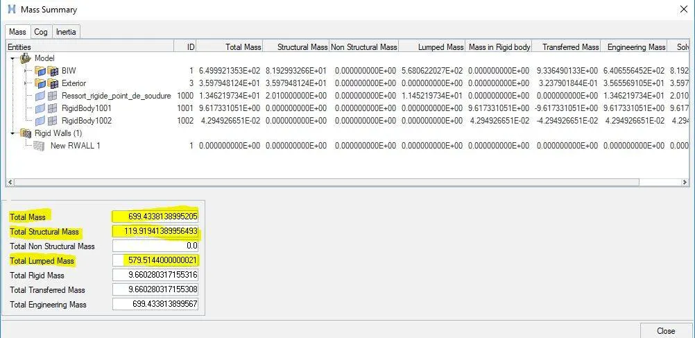
By adding the mass to the system, the COG of the model came to approximate centre. This makes the car to balance the weight on all the sides of the car.
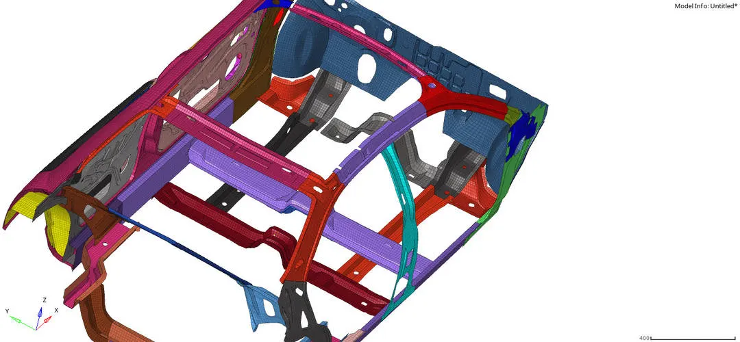
The mass is added in the lower parts of the model and the yellow node indicated in the floorbed of the car model is the COG point.
Time Step:
The last step is to setup the time step for the simulation to run. There are many types of time step formulation used in the RADIOSS, and in this case we took only nodal timestep and the interface timestep.
The timestep is mentioned for all the elements in the system and we can choose between the options present in the solver tab in hypermesh.
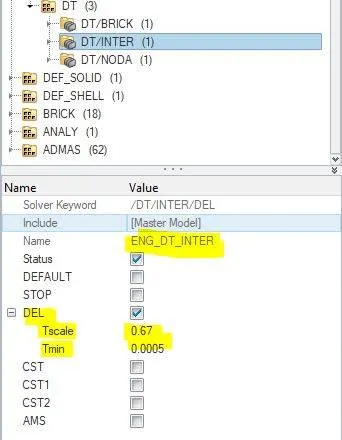
The interface timestep(/DT/INTER) controls the slave nodes during impact and del option is used in this case. This makes the slave nodes to get deleted from the contact interface during the impact within the d_search region and maintains the constant time step
is maintained.
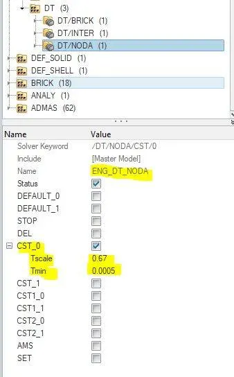
The Nodal timestep(/DT/NODA) controls the nodal impacts during crash and constant time step is maintained by using the default sacle factor of 0.67. This is used when the time step is less than than critical timestep the system adds some mass to the nodes to maintains the constant time step formulation.
QUALITY CHECK:
The quality check is done to maintain the stability in thye system and the time step formulation is the main factor to maintain the stability in the system. If stability increases the accuracy is increased and the simulation is good in nature.
The quality checks like initial penetrations, incompatible kinematic conditions, free nodes in rigid bodies are corrected using the command Tools--->model checker--->Radioss block.
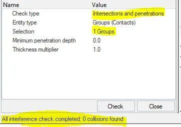
The initial penetration option is used to resolve the initial penetrations within the model before the simulation starts. It ensures the model stability during the simulation.
75DEGREE SIDEPOLE CRASH TEST:
The vehicle that is subjected to the crash is offsetted 15degree in zaxis at counter clockwise direction of the impact reference line. It is also known as Oblique sidepole crash test.
To offset the vehicle in xaxis the translate option is used.
Tools--->Translate--->select the node(at the centre)--->along zaxis--->angle--->translate.

All the model setup is smae for the oblique sidepole test(contact interface,mass addition,timestep) except the initial velocity and the rigidpole placement.
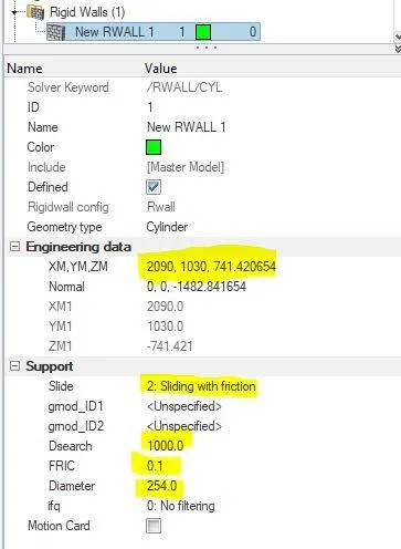
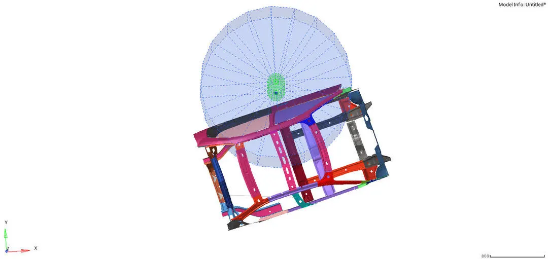
Creating rigidpole:
The side rigidpole is just moved slightly towards negative xdirection(global).
Initial velocity:
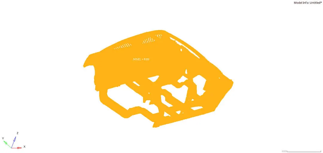
The velocity of the system doen't changed but the direction of the velocity is changed to the local coordinate system
(z direction). The velocity is given about 8.89mm/ms(29kmph).
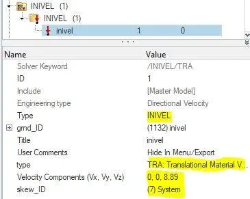
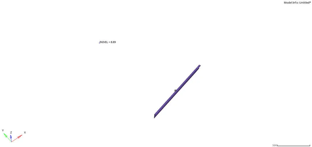
The fixed skew system is created with the zaxis opposite normal to the actual car impacting direction. The velocity is given in the zdirection at local system.
OUTPUT REQUEST:
There are three cases studied in the simulation output, they are;
Cross Sectional Forces in the cross member.
Intrusion at B pillar, hinge pillar and fuel tank region.Provide recommendation on what can help to reduce Fuel tank intrusion.
Peak velocity of inner node of the door.
CROSS SECTIONAL FORCE:
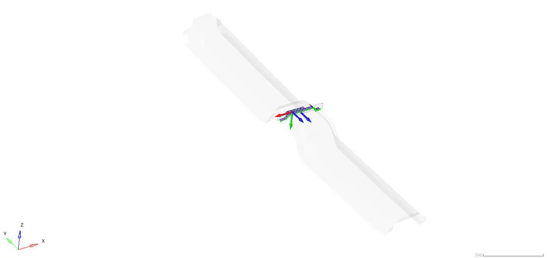
This is used to create a cross sectional area for the group of nodes/elements to observe the forces acting on the area. This is done by creating a local coordinate system with the nodes specified.
For creating a local system, an axis and a plane is created. The local system that we created makes sure of the forces acting normal to the system during the simulation.
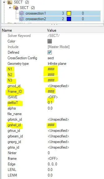
The N1(origin node),N2(axis node),N3(plane node) are local coordinate nodes of the local axis. Here the xy plane is used to create the local axes. The Frame_id is used to input the moving frame that we created. The deltaT is the time step for saving the data and it is given as 0.1. The shell elements and the tria elements are inputted into the cross sectional area.
Cross Sectional Forces in the cross member.
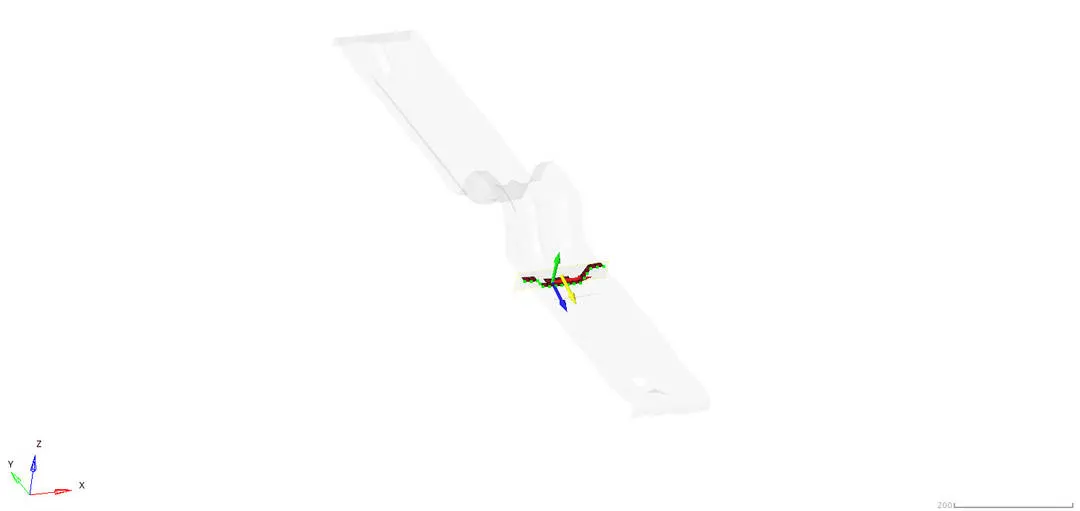
The sectional force acting on the cross member are created and the normal force acting to the area is found. The cross section is created in the local coordinate system not in global system.
The cross section is created in the two components on the floor bed of the vehicle.
Mid rail:
Seat reinforcement:
Intrusion at B pillar,hinge pillar and fuel tank region:
The intrusion for the midrails and hingepillar located in the underbody structure of the car is studied.
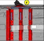
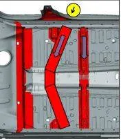
This is how the rail components in the underbody components behaved during the side pole crash. The simulation results contains the intrusion of the specific node in the Bpillar, Hingepillar, fuel tank region.
Bpillar:
Hinge pillar:
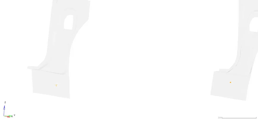
Fuel tank region:
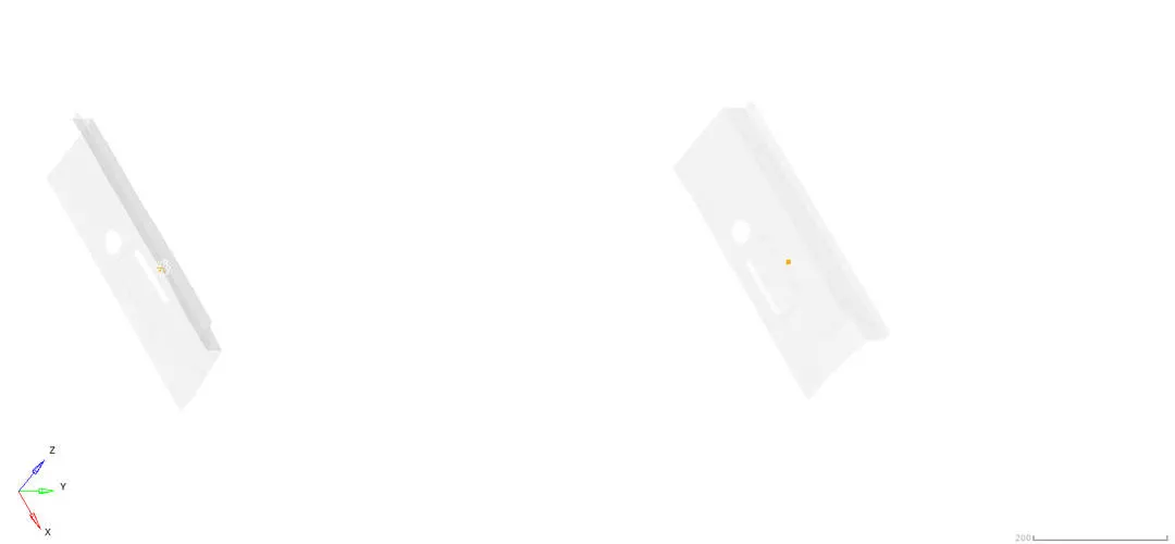
Peak velocity in the inner door wall:
The Bpillar is the first component to hit the rigid pole. The pole hits the doorwall in the initial condition of the impact. the max velocity of the doorwall after hitting the rigidpole is calculated. This is done because, according to the FMVSS the vehicle's airbag activating timing is calculated with the help of the velocity identification.
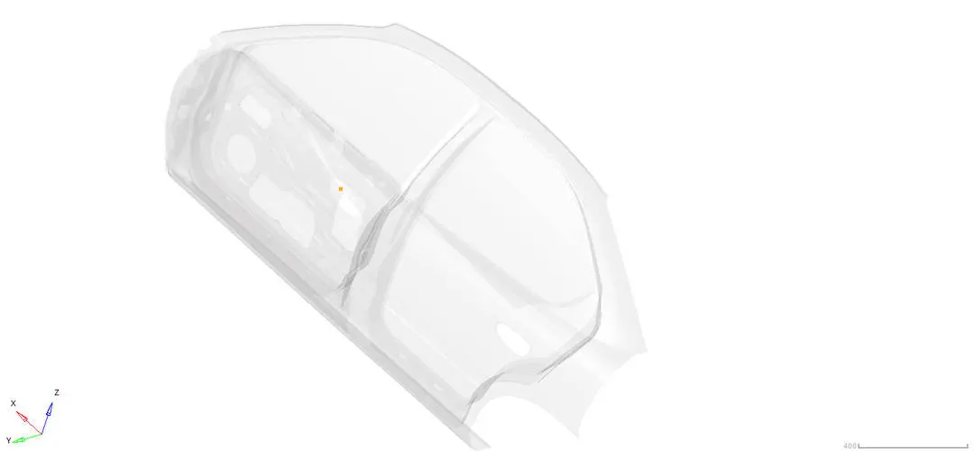
RESULTS:
90degree sidepole crash result:
Simulation result :
The hyperview is used to see the simulation results in the side view and the top view of the vehicle crash.
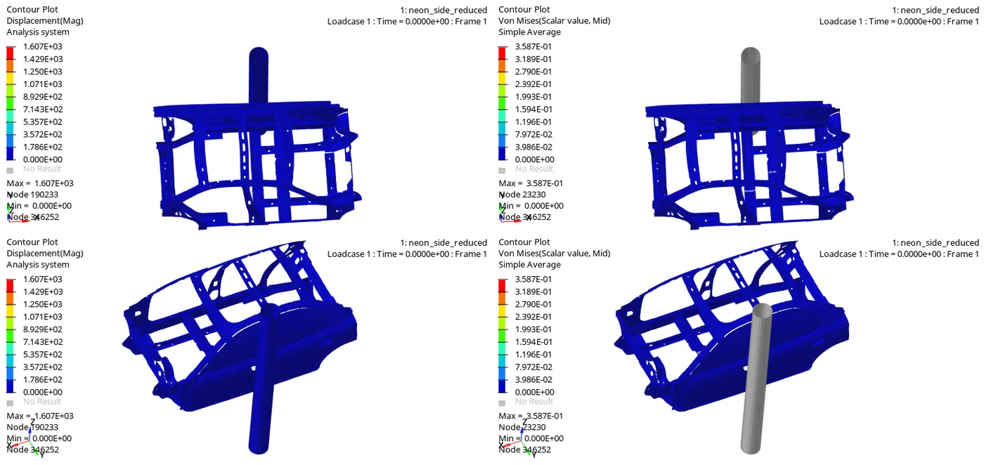
In this simulation the rigidpole is fixed and the impact angle of the car to the rigidpole is about 90degree. The Bpillar is impact line where it buggles the whole car for the velocity of 9.89mm/ms. the car frontal area and the rear end are reacting to the impact in the actual direction of the impact velocity.
Due to the impact the door panels are totally distorted and the midrail components are also fully deformed because it is in the main contact with the Bpillar.
The displacement is maximum in the front and rear ends of the vehicle making it to fold on the opposite direction to each other. This is because the velocity is maximum till the end as the rigidpole hits only the bpillar.
Plot results:
Total energy:
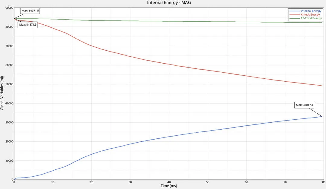
The total energy of the system remains constant as the internal energy increases with the decrease in the kinetic energy. The maximum energy in joule is about 84.371J.
Cross sectional force:
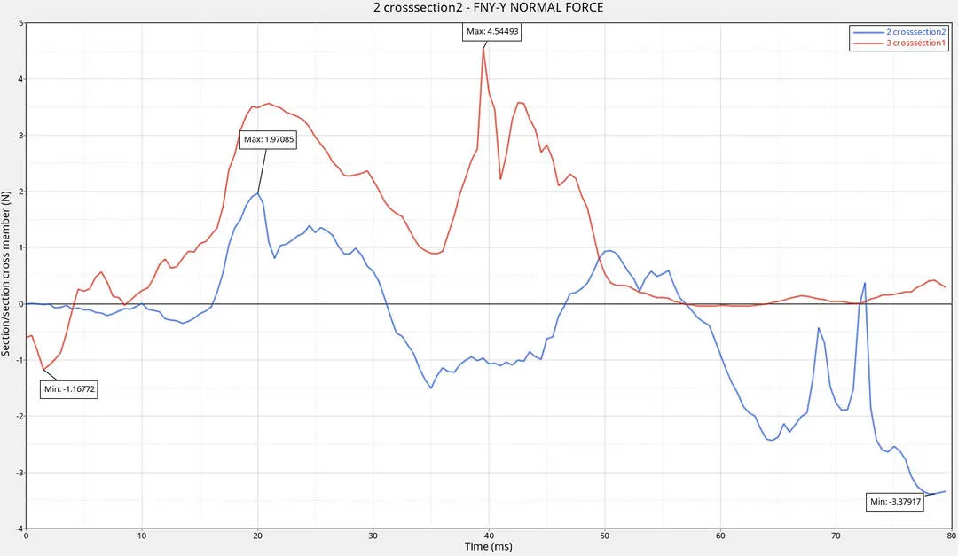
In this case of impact, we have to take sectional force acting normal to the axis of the surface. The midrails are taken for the cross sectional force creation. The section is created in the local negative ydirection in global system.
The redstrip indicates the midrail and the blue strip indicates the seat reinforcement parts. At the start the both the components remains zero because of the gap between the car and the pole. When the vehicle impact the pole the midrail component reaches the negative maximum and then reaches to peak at the 40ms of 4.54N.
The blue strip indicating the another midrail component shows us the sectional force amximum at the 20ms and the graph leads to the negative value at the end of the simulation. The negative direction of the force is came due to the section is located so close to the door panels, so when it deforms the midrails are also deforms faster.
Intrusions:
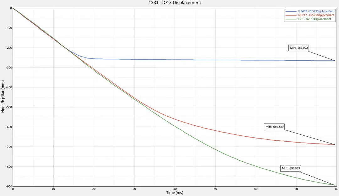
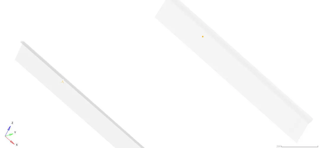
The node 123479 denotes the intrusion at the Bpillar; the node 125217 indicates the intrusion at the fuel tank; the node 1331 indicates the intrusion at the hinge pillar.
Due to the impact the node at the Bpillar doesn't displaced as mush as the other two nodes. The other two nodes displaced higher because it acts like the over hanging part on both the sides when the vehicle impacts the pole. Due to the initial velocity the both ends of the vehicle travels in the global Y direction and at one point the door panels buggles eachother.
Overall intrusions:
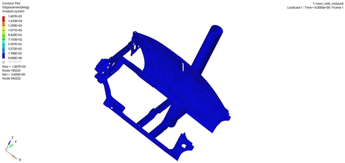
The rose colour strip indicates the node in the Bpillar, the strip at the right side indicates the node at the hinge pillar and the strip at the left side indicates the fuel tank region.
Velocity of the inner door:
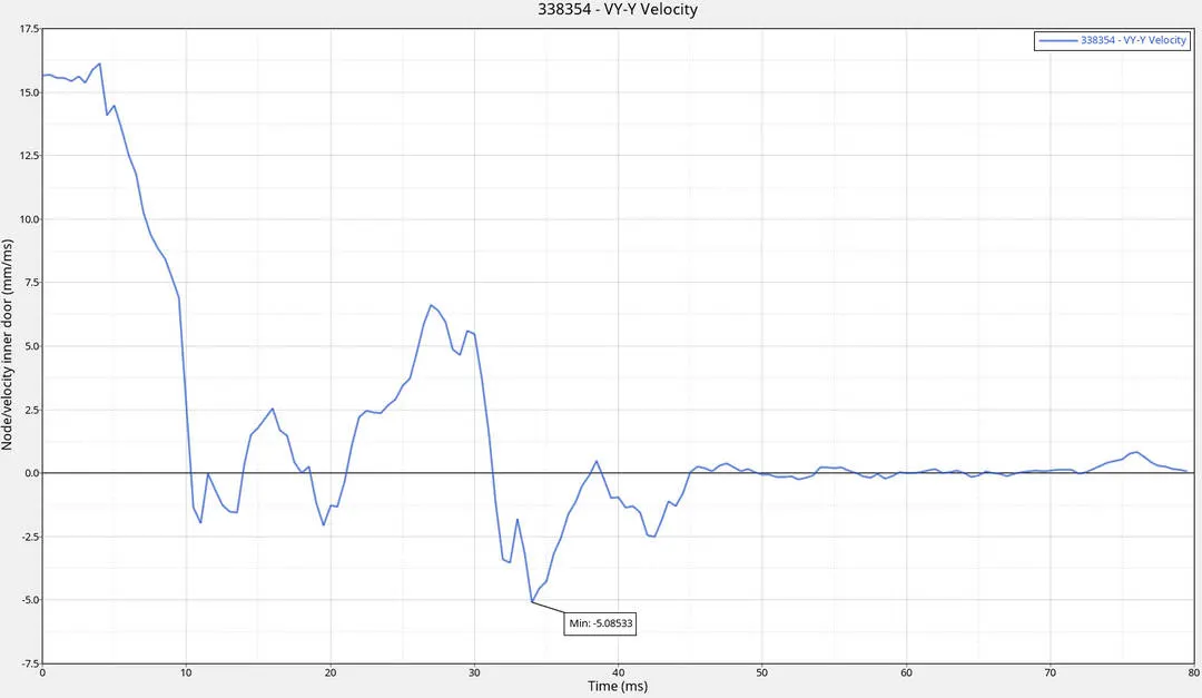
The maximum velocity of the system is in the start of the simulation and it drops simultaneously when it hits the rigidpole and gradually reduces it speed and comes to zero at the end of the simulation.
75degree sidepole crash result:
Simulation result :
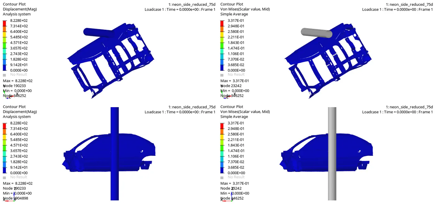
The second case is about to run the simulation by tilting the vehicle couterclockwise direction opposite to the global zdirection and the angle of offsetting is about 15degree.
The velocity of the system is 32kmph(8.9mm/ms). The change is not more than the previous case only the change is occured in the midrail component.
Plot results:
Total energy:
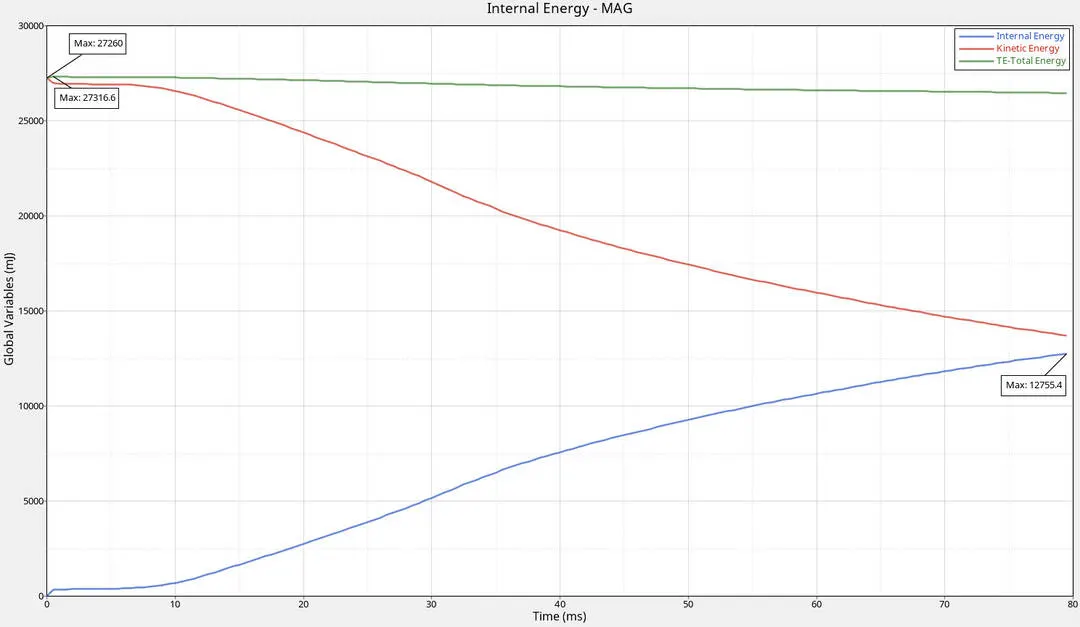
The total energy of the system remains constant as the internal energy increases with the decrease in the kinetic energy. The maximum energy in joule is about 27.316J. The internal energy is increased from zero to 12.755J by observing the kinetic energy of the system.
Cross sectional force:
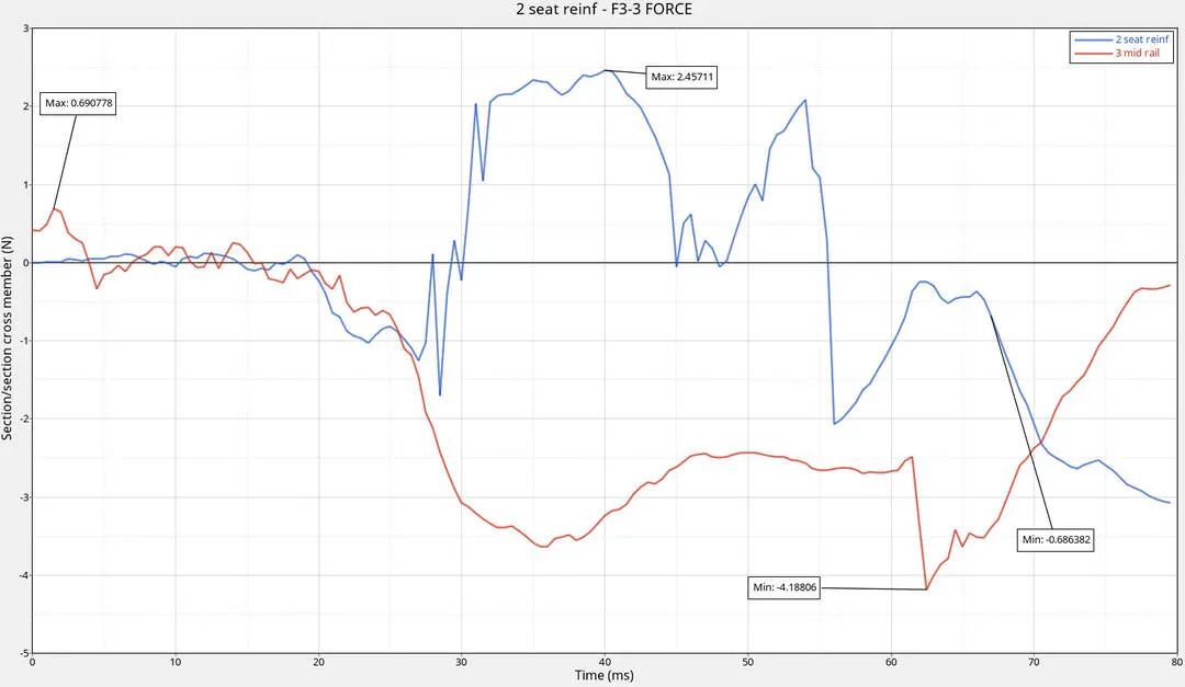
Both of the midrail components are at zero magnitude and when the impact done the midrail component haves the maximum normal force and suddenly drops to zero and then to the negative region because the Bpillar is in direct contact with the rigid pole even after the vehicle is offsetted. The normal is created when it hits the pole and the negative value indicated that the cross sectional area where the normal force acts is in local coordinate system.
The another midrail component(seat reinf) goes to negative direction after the half of the impact. at end both of the cross sectional force is in negative direction shows us the force is acting normal to the opposite of the vehicle motion.
Intrusions:
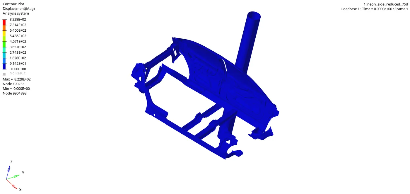
The two black strips indicates the intrusions on the nodes in the fuel tank region and the hinge pillar region. The white strip intrusion denotes the displacement in the Bpillar region.
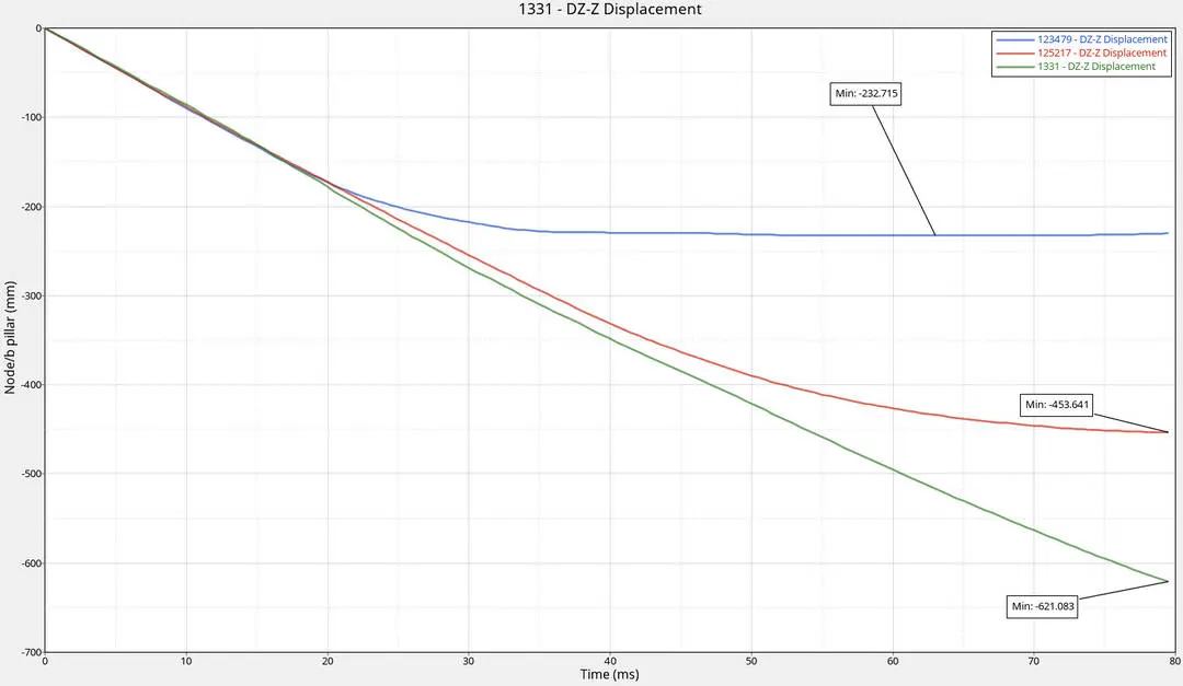
The displacement is maximum for the hinge pillar node reaching upto 621mm in n egative direction. The negative magnitude shows that the displacement is analysed in the local coordinate system.
Velocity of the inner door:
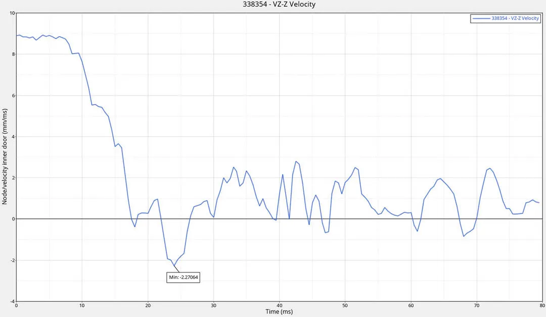
There is no any change in the velocity as the velocity is reduced gradually from the beginning and comes to zero at the end of the simulation.
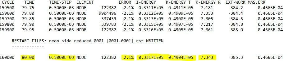
ENERGY ERROR FOR 75degree SIDEPOLE CRASH TEST:
ENERGY ERROR FOR 90degree SIDEPOLE CRASH TEST:
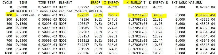

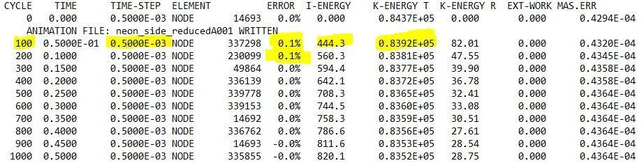
The energy error is maximum at the beginning of the simulation and at the end it is about -2.1%. This shows us that the system is in stable condition till the end of the impact.
OBSERVATION:
There are two types of sidepole crash tests are analysed, 90degree and 75degree sidepole crash. The vehicle that is subjected for the impact is offsetted 15degree in counterclockwise direction in impact's reference line.For 90degree pole test the vehicle is set perpendicular to the pole and subjected to the crash.
For 90degree and 75degree crash the Head Injury Criteria(HIC) and the thorax injury criteria are studied in the crash. From the standards we follow,the results tells us that the 90degree pole test is more reliable than the 75degree pole test. The main advantage of the 90degree pole test is it is common in the real world crash test.
The 75degree pole test is used only for the observation on opening of the airbag during the crash occured in the Bpillar in the sidepole crash.
The simulation for the sidepole crash is done for the deformation of the underbody structures. The intrusions and the cross sectional forces occurs on both the test are compared.
RESULTS:
The simulation havebeen runned for the 90degree and the 75degree sidepole crash test is analysed and I go through the crash standards FMVSS and learned about the loadpath, intrusions and the crash parametres used.