Week - 4 - Crash Box Simulation
Objective:
The objective of this challenge is to simulate how a crash box behaves during a frontal impact. In this challenge, we have assumed two cases first one is for a 1.2mm thick crash box getting in contact with a rigid wall and the second case is a 1.5mm thick crash box getting in contact with a rigid wall. The units system we are using in this challenge is gm-mm-ms.
Crash Box:
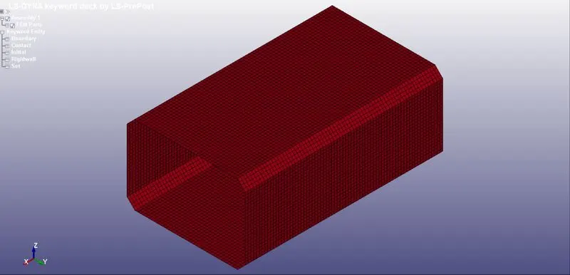
A crash box is a high-energy-absorbing structure that crashes on the application of loads and reduces the impact on other components nearby. A full-fledged cashbox is a highly sophisticated design but in this case, we will go with a rectangular channel which can be thought of as the most simple crash box.
RigidWall:
Here, In this model, they have not provided any rigid wall to us. Hence, we need to create a rigid wall.
In order to create a rigid wall, we need to go to create entity->rigid wall->create.
Here, there are many options available to create a rigid wall to the geometry but in this challenge, we have opted for the 3 nodes planar rigid wall.
We need to choose three nodes on the edge where you want to create a rigid wall.
Now, after selecting the three nodes you can see a rigid wall created, but here the rigid wall will act as an invisible plate because the rigid wall is having global coordinates as per the geometry. Hence, here we need to change the coordinates of the rigid wall to behave like a rigid wall in this simulation.
Now, after changing its coordinates we have to give a translational distance of about 30mm from the edge of the crash box.
Material:
Here in this challenge, we are using a Mat_024 material or Mat_piecewise_linear_plasticity material.
For this material, we will assign steel properties to the crash box.
The steel properties are represented in the gm-mm-ms unit system.
Section:
The FE model of the crash box is modeled with shell elements. In the software, we can use the keyword section tab to create shell elements of 1.2mm thickness for the crash box.
and for the second case, we need to assign another shell element thickness of 1.5mm.
Setup Initialization:
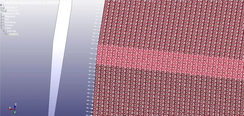
In this simulation, we have to set up the model in such a way that the crash box hits the Rwall at an impact velocity of 13.88mm/ms.
For this, we need to create an initial velocity card to apply velocity to the crash box in direction of impact.
A node-set Id is created for the crash box by selecting its nodes using the part selection option.
Contact Setup:
Contact in LS-DYNA is defined using contact surfaces.
A self contact is established in our model as there is only one surface. It is assigned by creating an Automatic_Single_surface contact card.
Boundary Condition:
It is one of the important cards which we need to assign to the model in order to run any simulation. Here we will create a spc_set boundary condition to the geometry with only x-translation degrees of freedom and all other degrees of freedom are fixed.
Control Setup:
This is the most important card which we need to assign to our model.
In LS-DYNA the control termination card is used to define the simulation end time.
Model checker and solving the model:
After creating all the necessary cards. Now, we can check the model for any errors if any clear those errors, and then solve the crash box simulation.
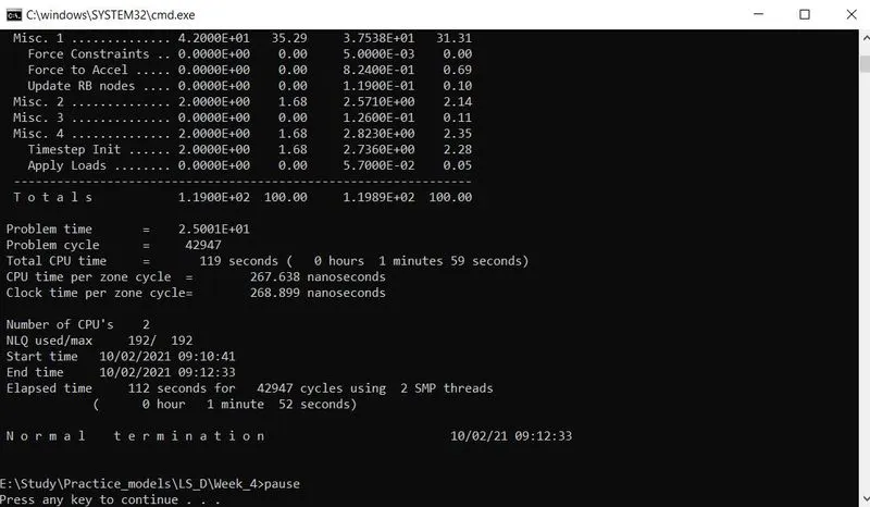
Here, we have achieved a normal termination and now we will check out the post-processing.
Animation of the simulation:
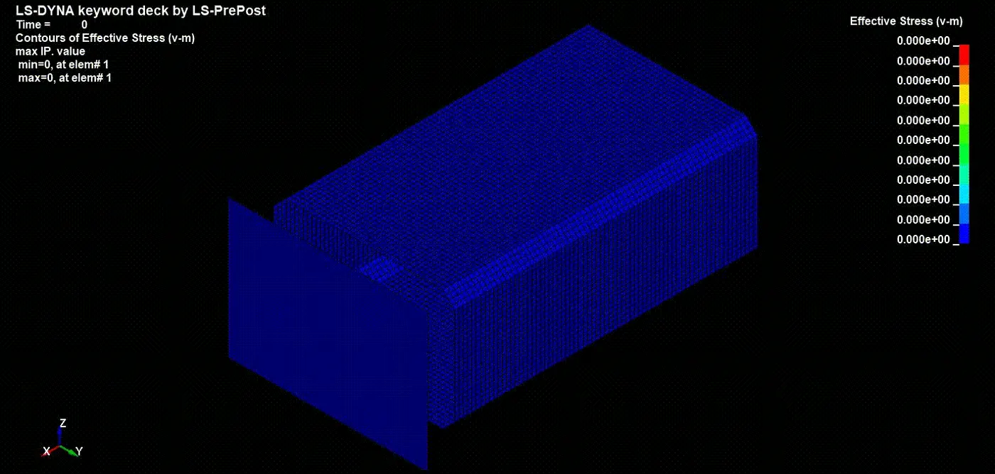
From the above animation, we can say that the crash box hits the Rwall and bounces back.
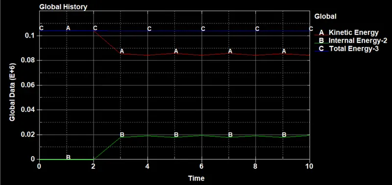
While bouncing back the crash box stores some amount of internal energy, which is known as Internal energy.
Case-1: 1.2mm Crash box(Energy graph)
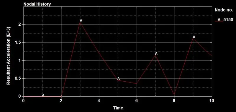
Case-1: 1.2mm crash box(Acceleration graphs)
Case-2: 1.5mm crash box(Acceleration graph)
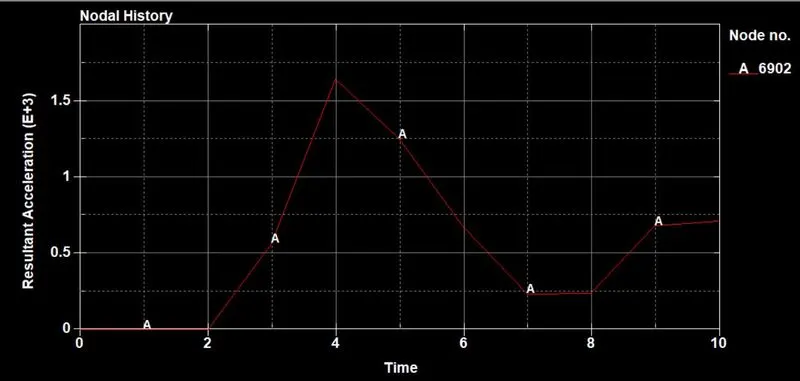
The above two graphs state the resultant acceleration vs time variation for the crash box at the mid node of the shell for both cases.
In case-1: 1.2mm thickness crash box, the maximum resultant acceleration is 2.2e^3 mm/ms at 3ms.
In case-2: 1.5mm thickness crash box, the maximum resultant acceleration is 1.7e^3 mm/ms at 4ms.
Comparison of Directional stress between a crash box of shell thickness 1.2mm and 1.5mm
Case-1: X-Stress
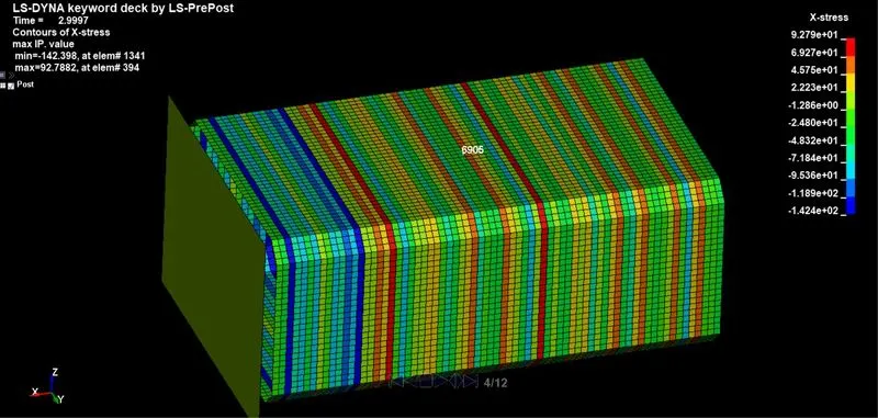
Case-1: Y-Stress
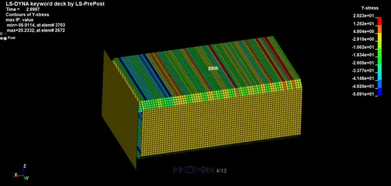
Case-2: X-stress
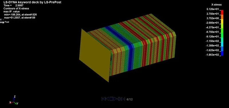
Case-3: Y-stress
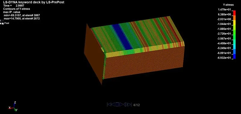
Crash box Thickness X-Stress Y-Stress
1.2mm 310.6MPA 316.5MPA
1.5mm 355.9MPA 210.1MPA
From the above table, we can say that x-directional stress is maximum in case-2 i.e for 1.5mm and Y-directional stress is maximum in case-2 i.e in 1.5mm thickness.
Case-1: X-Strain
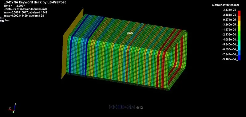
Case-2: X-strain
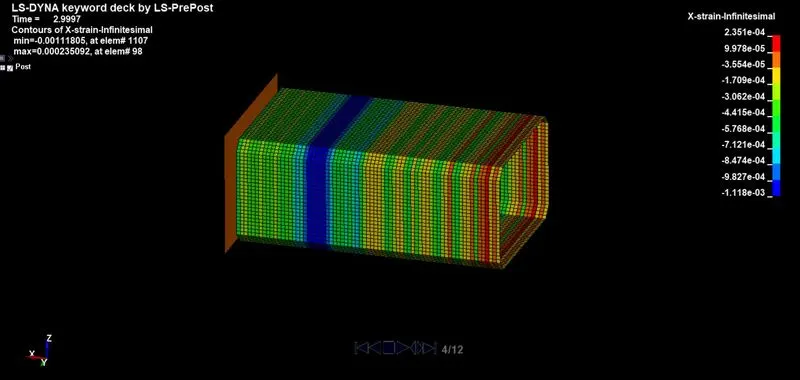
Crash box Thickness X-Strain Y-Strain
1.2mm 4.2E^6 1.03^5
1.5mm 3.39^6 7.58^6
From the above table, we can say that X-directional strain is maximum in case-1 and Y-directional strain is maximum in case-1.
Conclusion:
A simulation of the crash box for two cases of 1.2mm and 1.5mm thickness with a velocity of 13.88 mm/ms has been performed successfully.
From the above results, we can say that the crash box with a shell thickness of 1.5mm has better stiffness and energy absorption rate as stress increases during the impact than that of 1.2mm thickness.