Week 5 Bending of iPhone
Objective:
To run the simulation of bending of Iphone.
Case 1: Simulate the model as it is given in the video
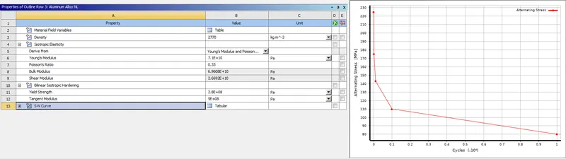
Case 2: Move the bottom fingers from their defined position to the given position X= 22.5mm & Z= 10mm and obtain the results for the simulation. Also define the S-N curve for the Aluminium Alloy material as per values given below and determine the fatigue life results for the same.
| Stress, MPa | Number of Cycles, N |
| 225 | 10000 |
| 175 | 100000 |
| 143 | 1000000 |
| 110 | 10000000 |
| 80 | 100000000 |
Solution:
-Firstly, we need to import the geometry to ANSYS workbench.
-Assign the required materials in our Directory.
-And in Aluminium alloy NL we need to provide the S-N graph
-Now, import the geomrty to Space claim and check for any abnormalities.
-If there are any then solve those and open the geometry in mechanical module.
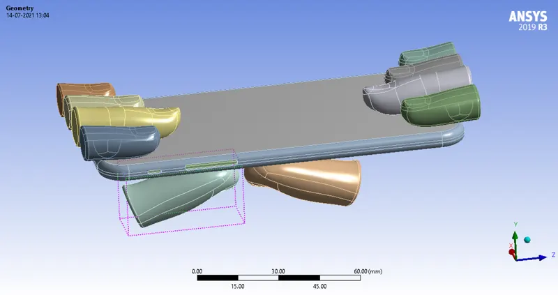
-Now, assign the materials to the geometry where there are necessary.
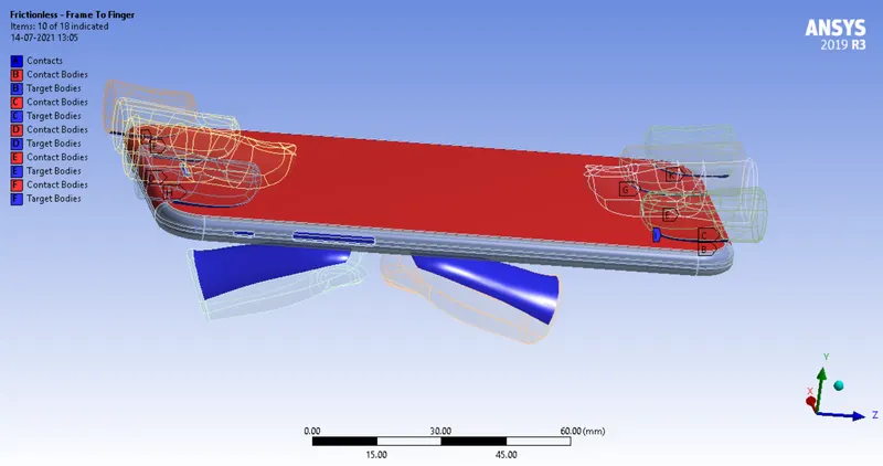
-After finishing that check the connections which are defaulty applied. If there are any questions marks present in the connections tab you can delete those connections. Change the contacts execpt the right thumb to frictionless contact and leave the right thumb contact as bonded.
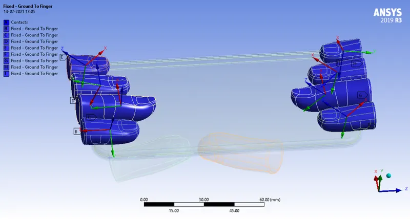
-Now, create joints to the geometry the top fingers will have fixed joints where the bottom thumbs will have translational joints.
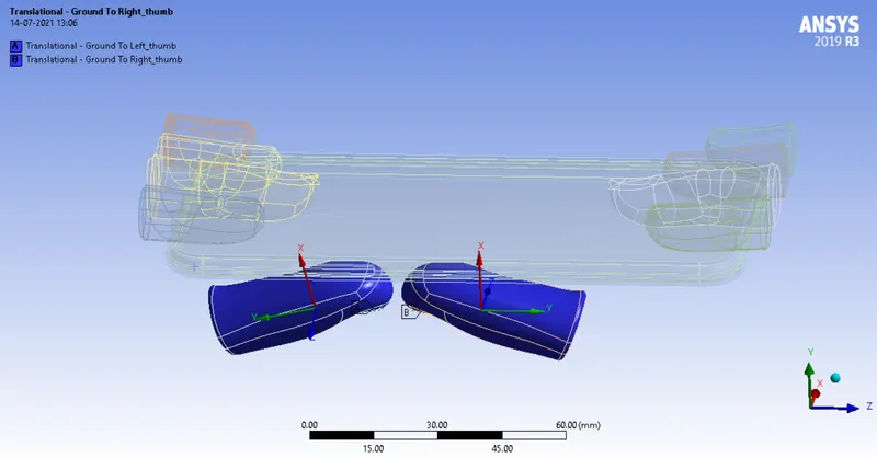
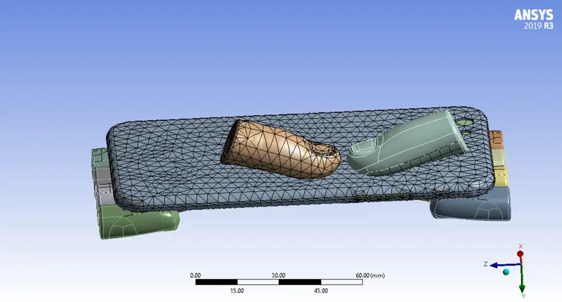
-After assigning the joints we have to mesh the geometry with 4mm for the surfaces which are in contact and default for the rest of the surfaces.
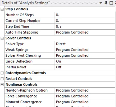
-Now, we have to provide boundary conditions to the geometry in analysis settings to run the simulation.
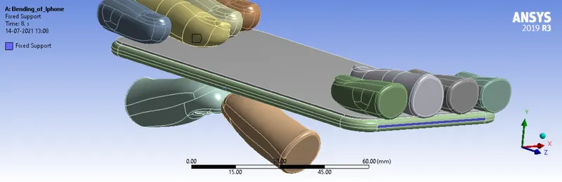
-Now, we have to assign fixed supports to the geometry.
-After that we have to assign the displacement
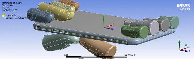
-Now, both translational joints
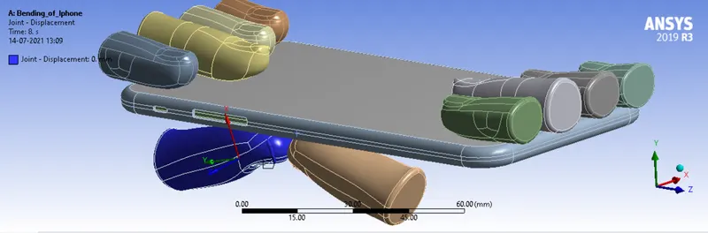
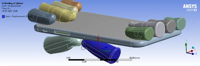
-Now, provide the output paramanets to the simulation and run the simulation.
Case-1
Deformation:
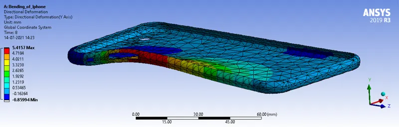
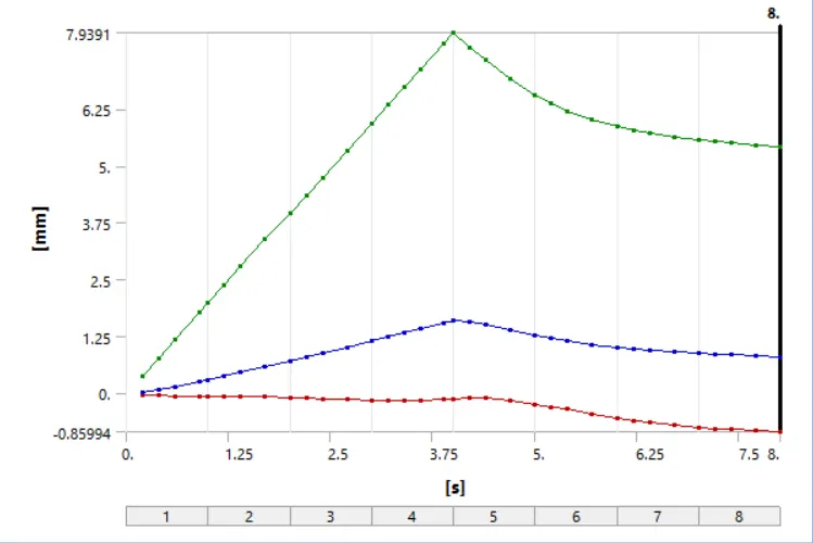
Deformation_graph:
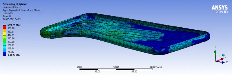
Equivalent_stress:
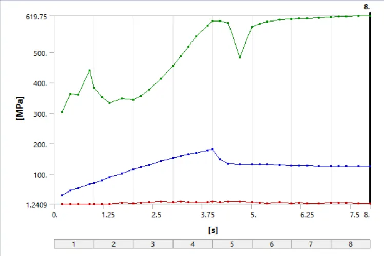
Equivalent_stress_graph:
Case-2
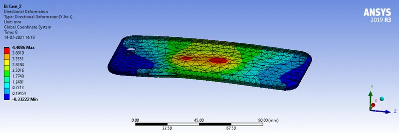
Deformation:
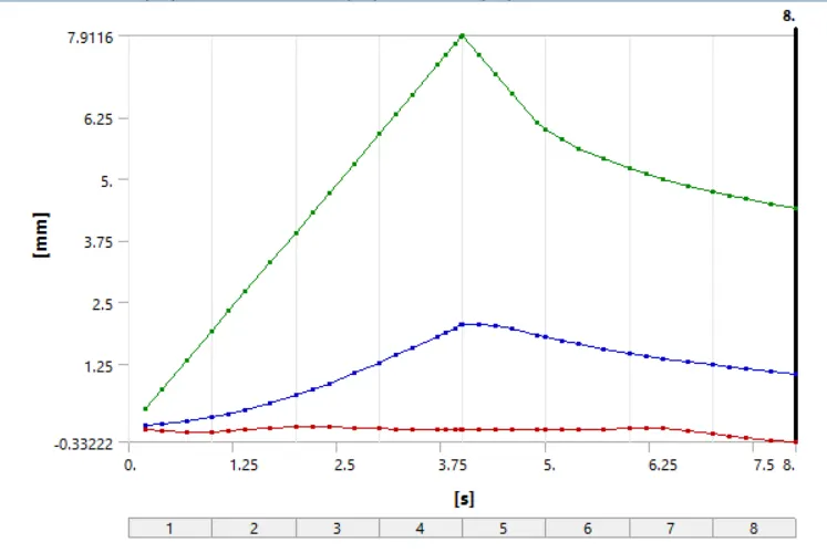
Deformation_graph:
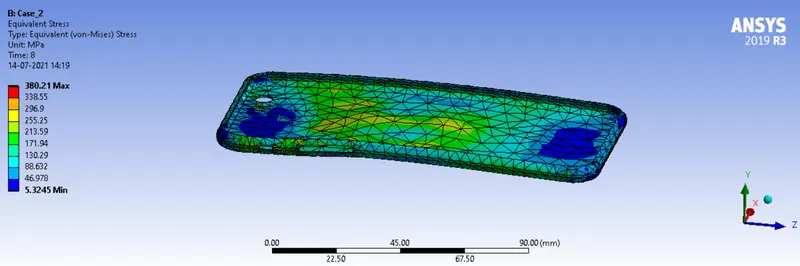
Equivalent_stress:
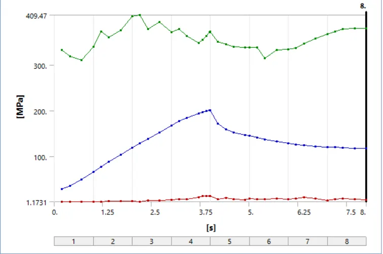
Equivalent_stress_graph:
Comparision Table:
Equivalent Stress(MPa) Deformation(mm)
Case-1 619.75 5.4157
Case-2 380.21 4.4086
Simulation Animation:
Conclusion:
As you can see from the the table above we can say that the Equivalent stress and Deformation for case-1 is higher than that of case-2. That is because in case-1 we have begin bending the component at the edge where as in case-2 we have begin to bend the component at the centre of the geometry. Hence when we bend the geometry at the edge it's life decreases when compared to that at the middle.