Assignment 5
AIM: Run the simulation of crash tube various cases and caompare the results for all cases
ABSTRACT:
- Create the mesh for the bumper assembly
- Joint the parts in bumper assembly using with spot weld
- Run the simulation of crash tube in various cases
- plot the graphs contact forces,internal energy and Create
- compare results for all cases.
PROCCEDURE:
- Import the bumper assembly model
- FILE >IMPORT>GEOMETRY>IMPORT In radious profile
- Mesh the component. mesh size should be 6
- 2D > AUTOMESH > select SURFACE >click on MESH
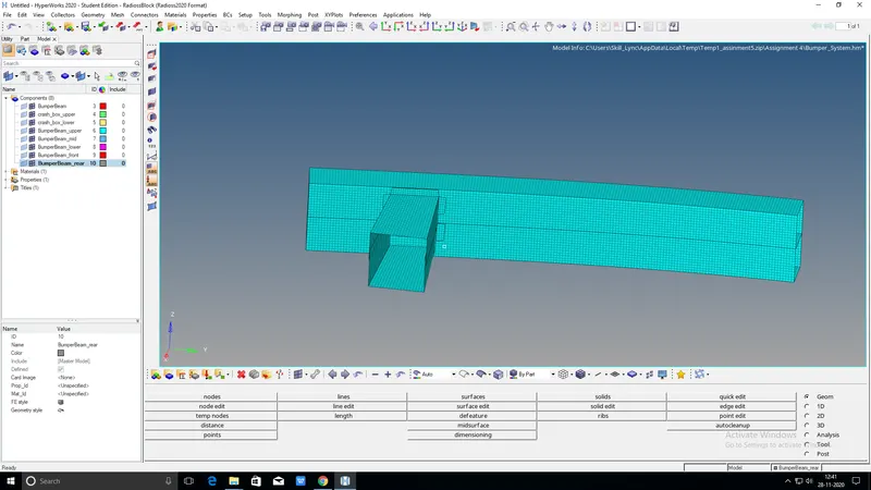
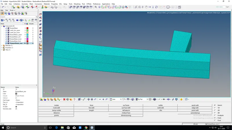
- After mashing the componentweld the parts in bumper in assembly
- using the spot weld would connect the joints
- Select 2D > Connectors > spot option
- select the location were weld has to be created,by clicking the node list
- Tick the click box retain nodes
- Specify the facing depeds on gap between the two parts
- give the tolerance value 10 and click on the weld .then spot weld is created

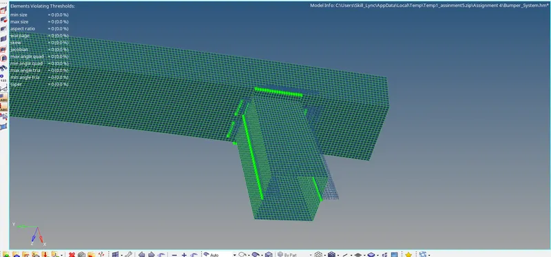
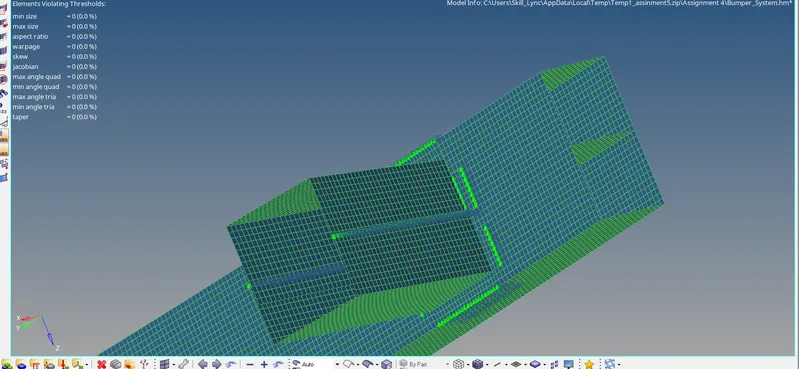
PIC:SPOT WELD THE PARTS OF BUMPER ASSUMBLY
RUN THE SIMULATION CRASH TUBE MODEL:
case1:
- Import the notch tube model.in radious profile
- FILE>IMPORT >SOLVERDESK>select FILE >IMPORT
- Run the simulation as it is do not any changes in this case
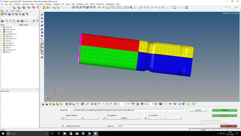
- Go to analysis and right click on the includers give option to nt 4 and save as case1.click on radious and run the simulation
- Aftrer completed the simulatiom then go to hyper view
- in hyper view select the file h3d from case1 click apply in hyper view and get the animation
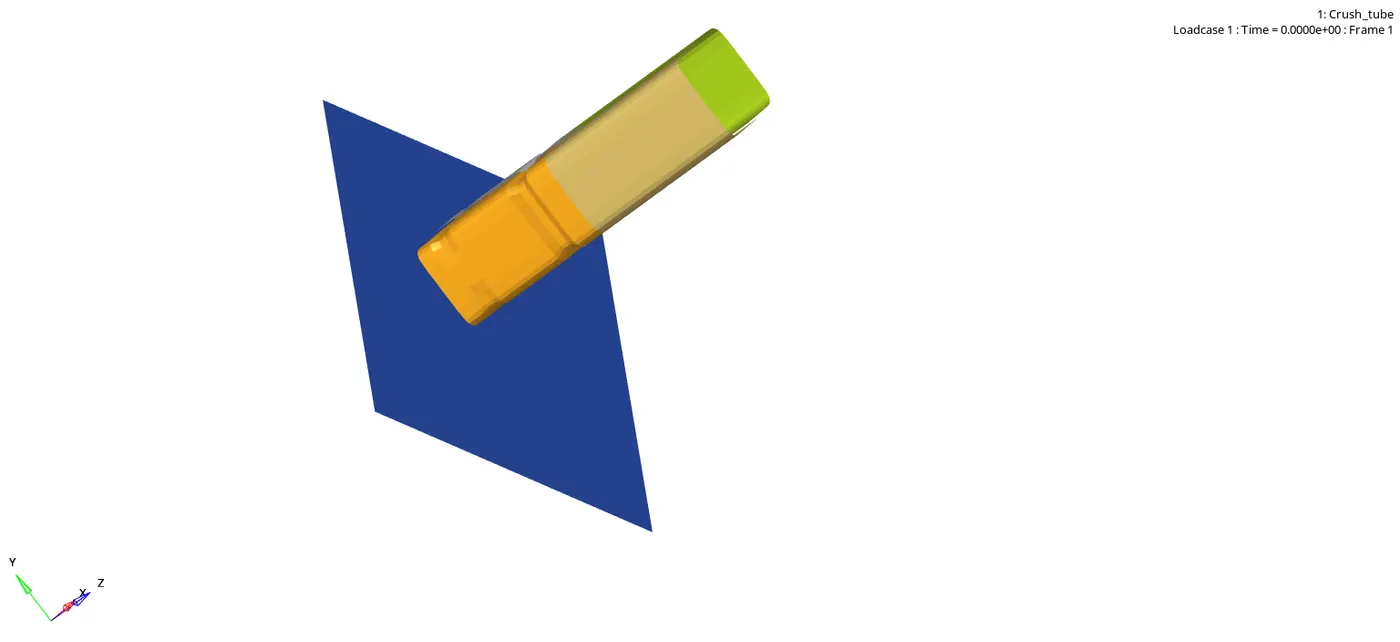
- completed animation than will go to hypergraph
- Select the parameters mm,ms and kg
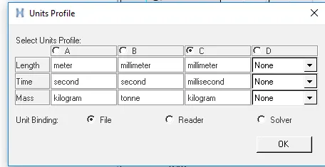
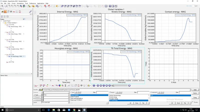
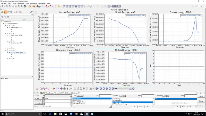
- in hypergraph Plot contact energy,internal energy,kinetic energy,copntact energy and total energy.and Create
CASE2:
- Imort the run file000 from case1
- FILE>IMPORT >SOLVERDESK>select FILE >IMPORT
- Change the inacti=6,Run the simulation
INACTI: Deactive flag of stifness in case of initial penatration
inact6: gap is variable with time. but initial gap is adjusted
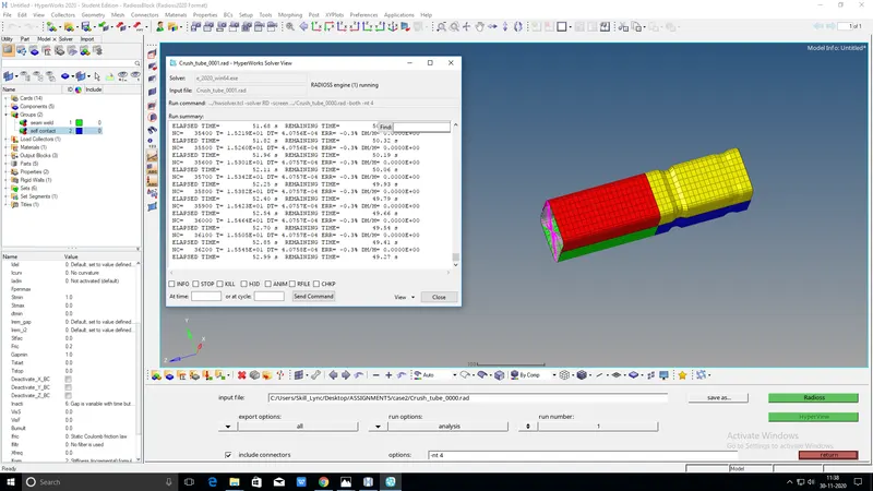
- Go to analysis and right click on the includers give option to nt 4 and save as case2.click on radious and run the simulation
- Aftrer completed the simulatiom then go to hyper view
- in hyper view select the file h3d from case1 click apply in hyper view and get the animation
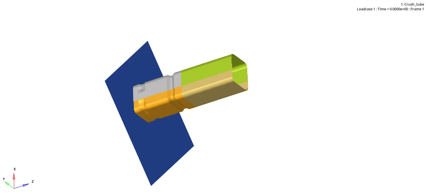
-
- completed animation than will go to hypergraph
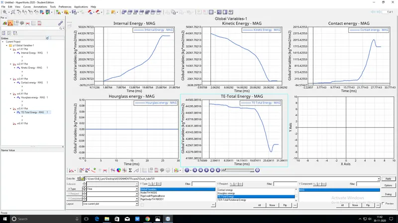
- in hypergraph Plot contact energy,internal energy,kinetic energy,copntact energy and total energy.and Create
CASE3:
- Imort the run file000 from case2
- FILE>IMPORT >SOLVERDESK>select FILE >IMPORT
- create the card image type11 contact
- select the 4 components in line 1 and 2 ids
- Run the simuklation and save as case 2
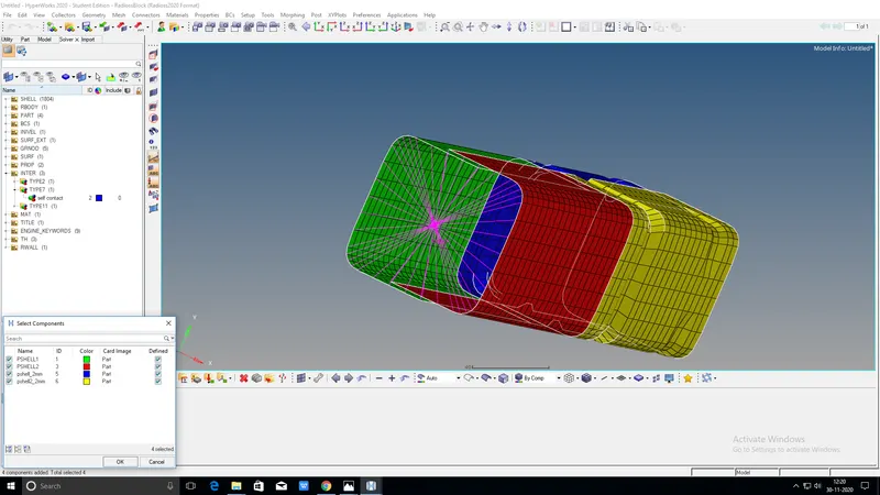

- Go to analysis and right click on the includers give option to nt 4 and save as case2.click on radious and run the simulation
- Aftrer completed the simulatiom then go to hyper view
- in hyper view select the file h3d from case1 click apply in hyper view and get the animation
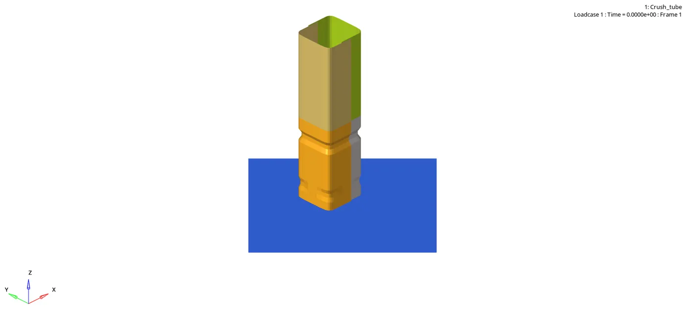
- completed animation than will go to hypergraph
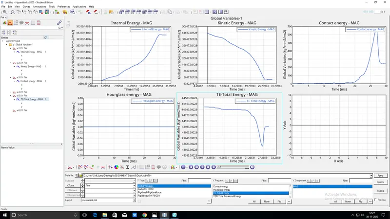
- in hypergraph Plot contact energy,internal energy,kinetic energy,copntact energy and total energy.and Create
CASE4:
- Imort the run file000 from case3
- FILE>IMPORT >SOLVERDESK>select FILE >IMPORT
- Delete the boundary conditions And remove the notches
- already have th(time history) so dont create
- Run the simulation and save as case4.
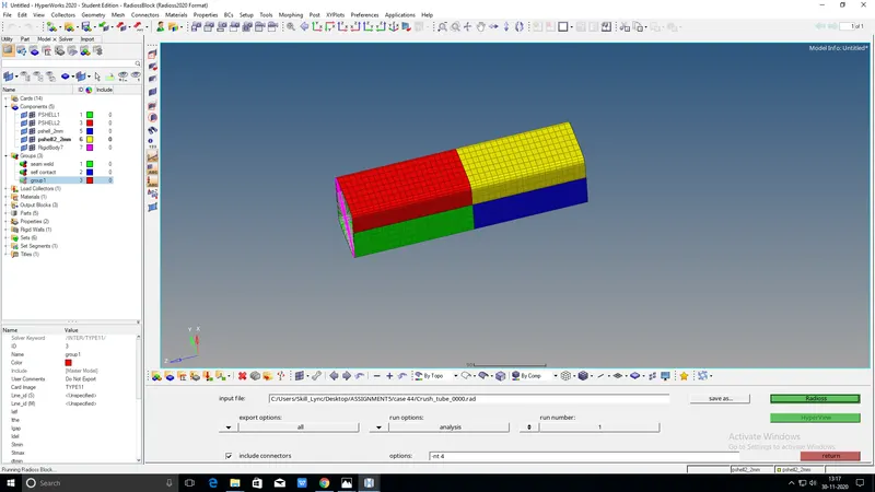
- Go to analysis and right click on the includers give option to nt 4 and save as case2.click on radious and run the simulation
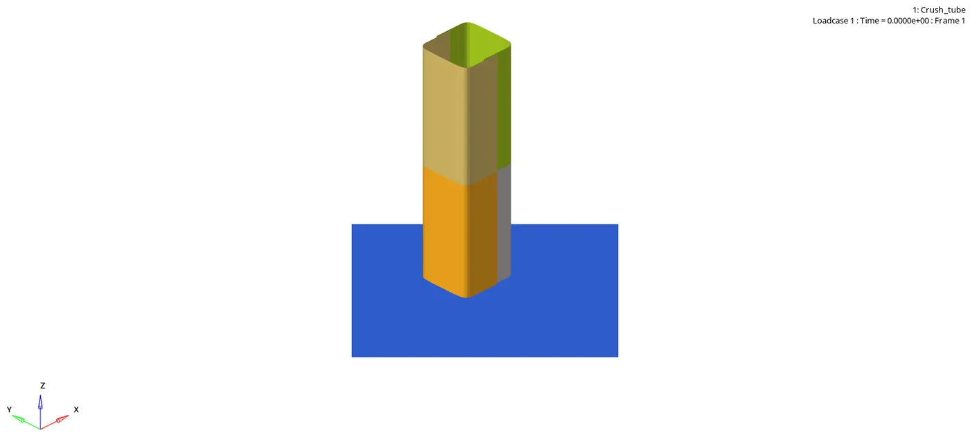
- Aftrer completed the simulatiom then go to hyper view
- in hyper view select the file h3d from case1 click apply in hyper view and get the animation
-
- completed animation than will go to hypergraph
- in hypergraph Plot contact energy,internal energy,kinetic energy,copntact energy and total energy.and Create
CASE5:
- Imort the run file000 from case 4
- FILE>IMPORT >SOLVERDESK>select FILE >IMPORT
- create the notch inthe middle of the tube
- Run the simulation save as case5
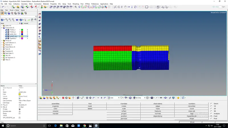
- Go to analysis and right click on the includers give option to nt 4 and save as case2.click on radious and run the simulation
- Aftrer completed the simulatiom then go to hyper view
- in hyper view select the file h3d from case1 click apply in hyper view and get the animation
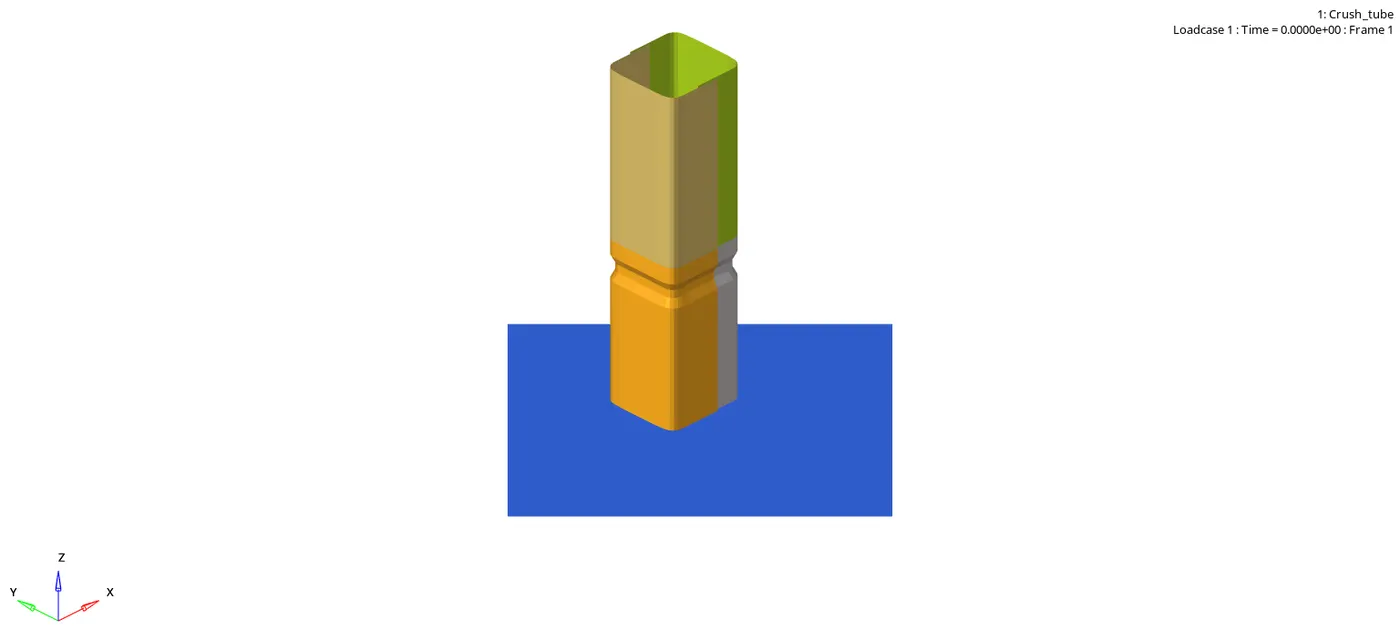
- completed animation than will go to hypergraph
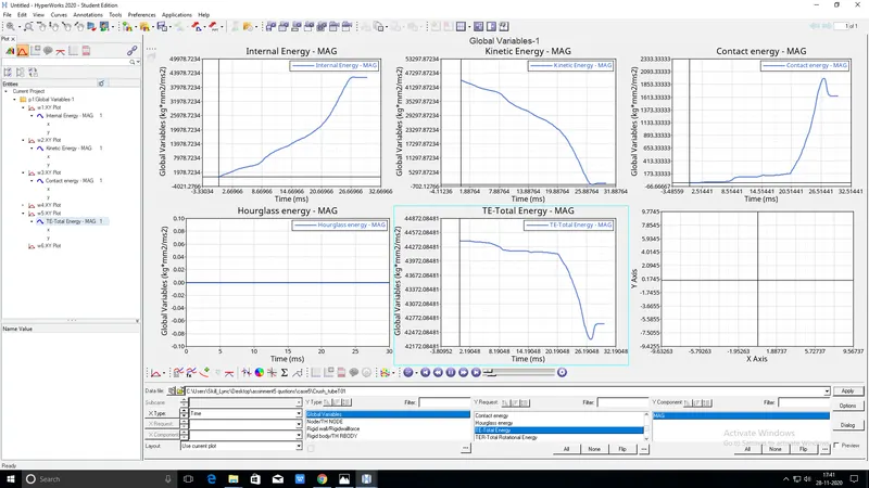
- in hypergraph Plot contact energy,internal energy,kinetic energy,copntact energy and total energy.and Create
CASE6:
- Imort the run file000 from case 5
- FILE>IMPORT >SOLVERDESK>select FILE >IMPORT
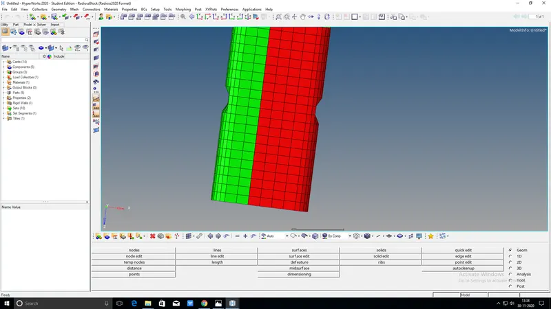
- Create a new notch with nodes only from opposing 2 faces
- Run the simulaion and save as case6
- Go to analysis and right click on the includers give option to nt 4 and save as case2.click on radious and run the simulation
- Aftrer completed the simulatiom then go to hyper view
- in hyper view select the file h3d from case1 click apply in hyper view and get the animation
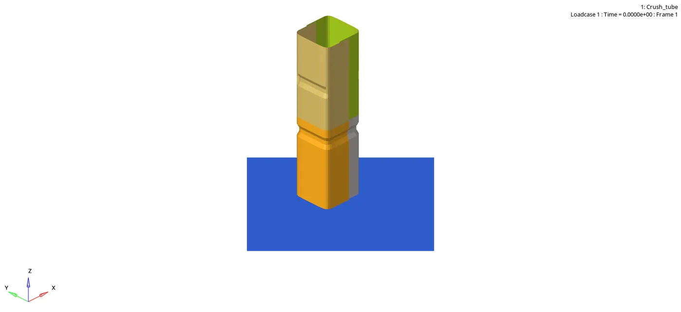
- completed animation than will go to hypergraph
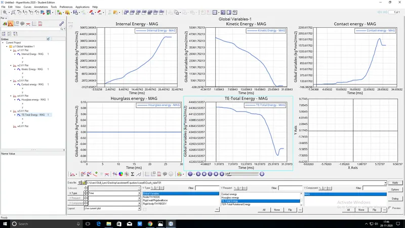
- in hypergraph Plot contact energy,internal energy,kinetic energy,copntact energy and total energy.and Create
COMPARISON:
1.Whatever forces apllied on the crash tube.it will deformed. we can see the rebounded of the deformedcrash tube because of the convertion of the internel energy to little bit of kinetic energy. contact energy due to the type7 contact in the model is plotted above.type 7 is created non linear forces.
2.inacti is the action wich is solver is going to do initial pentrations in this model. inacti 6 reduces the gap. the energy curves are same as 1st case. and hourglass is constant in both cases
3.in this case have extra edge contact type11.energy curves doesnt show any difference compare to 1st and 2nd cases energies are flowing same path.slight dip contact energy due to penetrations.
4.heare we removed notch deformation will start the end near to the rigid.but in other cases deformation start notch region
5.in this case contact force is low and hour glass energy also constant and conatact energy is zero in begaining after few sec will raise the contact energy
6.energy graphs are looking same . and kinetic energy comes to zero and total energy is coserved
CONCLUSION:
THE NOTCHES WERE COMMANLY USED ENERGY ABSORBING STRACTURES UNDERGOING AXIAL COMPRESSIVE CRASH.THE NOTCHES PLAY KEY ROLE IN SMOOTH ENERGY TRANSFERING DURING AXIAL CRASH ANALYSIS.