Week 11 - Final project
DESIGN AND DEVELOPMENT OF CAR INTERIOR DOOR TRIM
AIM:
Creation of car interior door trim CAD model considering following inputs as like in OEM and tier1 companies
- a) Class A surface
- b) Nominal thickness: Refer to master sections
- c) Attachment strategy :
ABSTRACT:
- Checking the class A surface
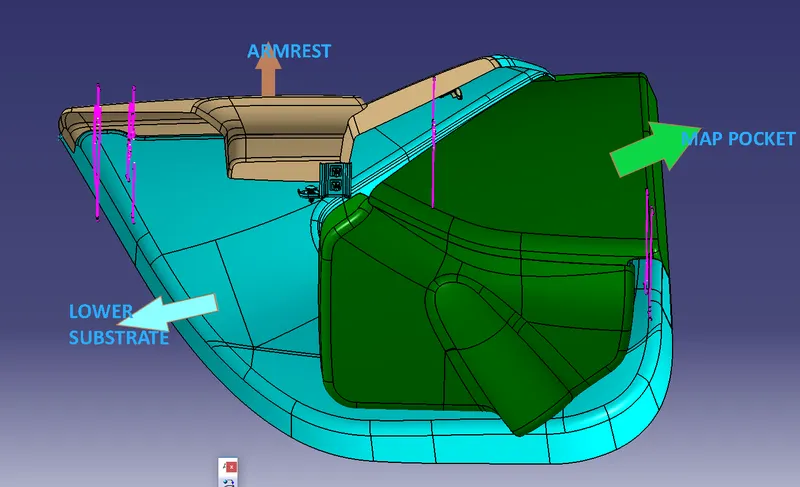
- Separating class A into MAP POCKET, LOWER SUBSTRATE, ARMREST, AND MASTER SECTIONS
- Divide the map pocket and armrest into two parts.
- Creating required flanges on map pocket and armrest. using with given master sections.
- Generating class B and class C surfaces
- Join the class A and class B and Class C surfaces
- Generating the solid on closed surfaces
- Create feature parts such as doghouses and heat stakes on required parts.
What is a master section?
-
Master sections are the guides for design requirements that decide the component packaging after technical (Styling, Concept, or Class-A) surfaces.
DESIGN LIFE CYCLE:
- Concept sketch: concept sketch is a freehand sketch draw on paper.
- styling class-A: styling class A is designing a sketch using computer software allies.
- Feasibility check: feasibility is nothing but a concept sketch check. all the components checked for a requirement. after completing the feasibility check move to the concept validation.
feasibility check is nothing but changing or remodel the visible components for getting a new look for the product.
For example in the car change steering, the dashboard for changes the look for a new feel. but doesn't change the steering rod because the steering rod is not visible in the car it's an inner part.
- Concept validation: Concept validation allows you to build a detailed understanding of how your current and target customers feel about the core aspects of your offering before it’s launched in-market.
- New product design and development: Designing and developing outstanding new products is a challenging exercise, given the fact that it requires expertise across multiple domains. The evolution of a product happens over time with constant research, analysis, design studies, and prototyping. The product learns its lessons and evolves in the real world by incorporating that knowledge. Onward Technologies' expert team understands these challenges and provides you with end-to-end product design and development services that match your imagination.
- proto built: once proto built is done. the design is validated and no more changes acceptable. later will go pilot production.
- design validation: design validation is a process of evaluating the software product for the exact requirements of end-users or stakeholders. The purpose of design validation is to test the software product after development to ensure that it meets the requirements in terms of applications in the user's environment.
- pilot production: in this pilot production minor changes in design. pilot production will give you information about failures in molding and other plastic defects formed during the pilot production. correct everything before going to mass production.
- MASS PRODUCTION: Mass production is the manufacturing of large quantities of standardized products, often using assembly lines or automation technology. Mass production facilitates the efficient production of a large number of similar product
PROCEDURE:
-
DESIGN THE LOWER SUBSTRATE, MAP POCKET, ARMREST.
SEPARATION OF CLASS A SURFACE:
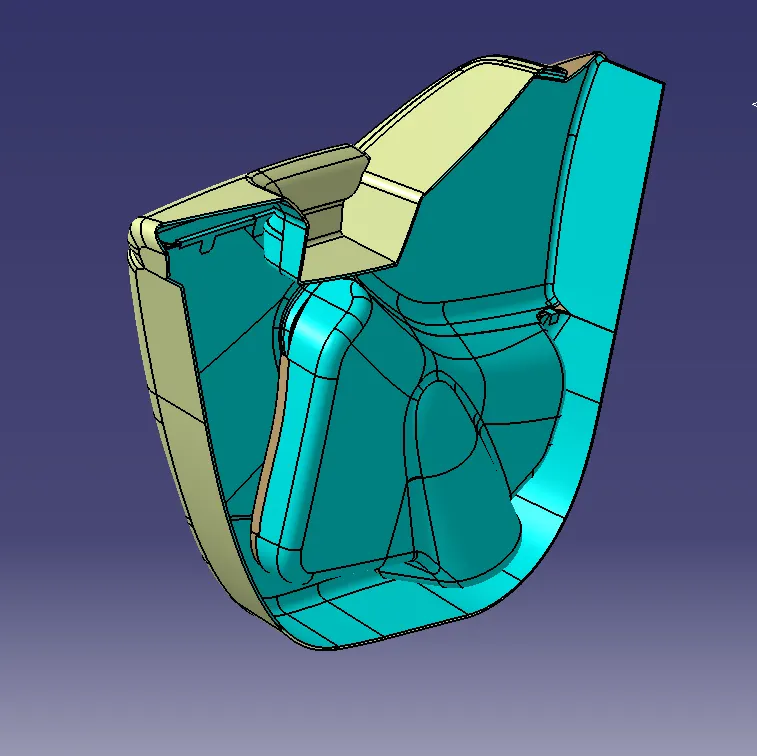
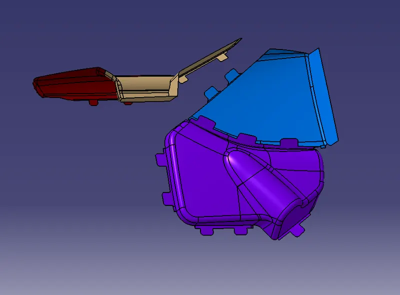
Class A surface consists of three major parts
- Map pocket
- Armrest
- Lower substrate
- After That map pocket and armrest components divide into two parts
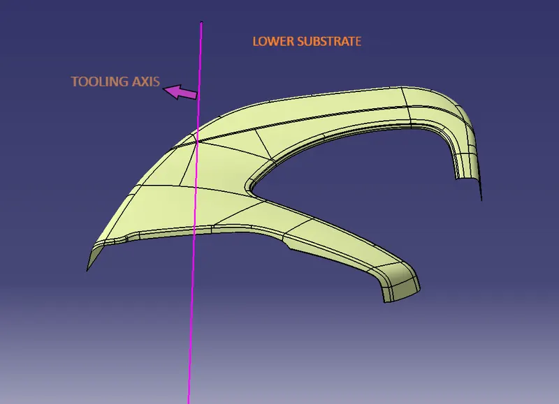
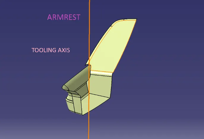
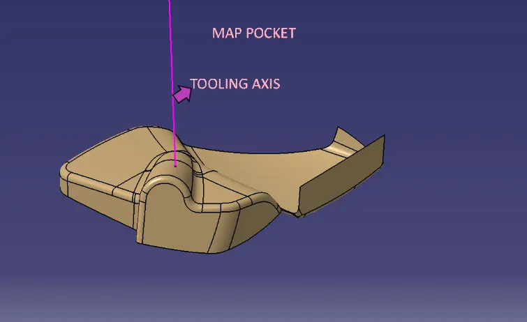
- Then will go to create tooling axis and slider axis for each component
CREATE TOOLING AXIS:
Tooling axis is nothing but the direction of the core and cavity open and closed.
B SURFACE CREATION:
Class B surface is created by offsetting the class A surface outwards with the measurement as per the master section i.e., 2.5mm.
CREATE FLANGES & C SURFACE CREATION:
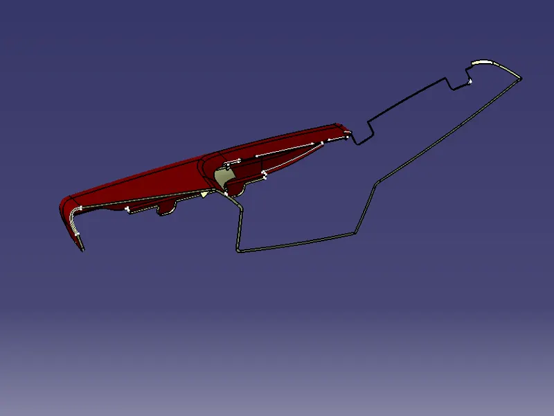
As per the master sections provided for each component, create the flanges for the class A surface in the required positions. Steps to be followed for creating the flanges:
- Extract the edges of the class A surface wherever required to create flanges.
- Using the sweep option create the surface perpendicular to the class A surface as shown below.
- The angle of the swept surface should be closer to the master section lines when measured. Set the angle closest to the master section lines.
- Extract the master section lines and create a line on the sweep surface using the intersect option.
- Measure the angle between the extracted lines and adjust the sweep surface angle until the angle between both the lines is near to 0 degrees
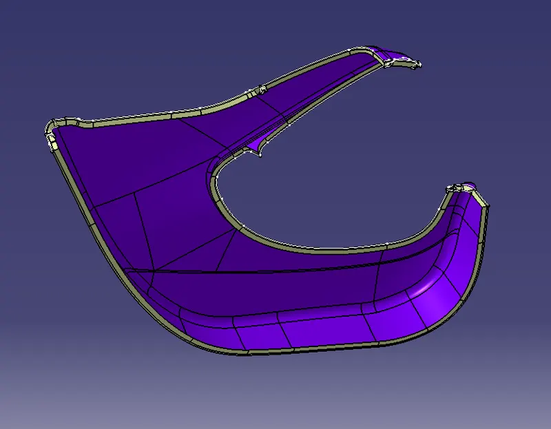
After creating the flanges for the component, create the class B and C surfaces from class A surface following the steps shown below:
- Extract the edge lines of the class A surface and sweep the extracted lines.
- Set the sweep mode to draft direction, select the extracted lines as guide curves, and the tooling axis as the draft direction. Set the sweep angle as 3 degrees and the length of sweep more than 2.5 mm.
- The sweep operation cannot be used in few regions i.e., near curved surfaces. The surface is to be created using blend or multi-section surface operations.
- Join the swept and blended surfaces together for creating the total Class C surface.
 .
.
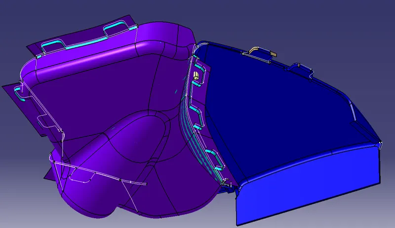
- Now trim the class B and C surfaces as required to create a thickness of the component.
- After trimming the Class B and C surfaces join the Class A surface together.
- Check for any kind of open edges between the joined surfaces using the boundary feature. Fix the open edges if any.
- Now create a solid component for a closed surface component using the ‘Closed’ feature in the part design window. The solid will not be formed if there are any kind of open edges.
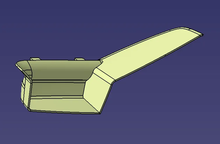
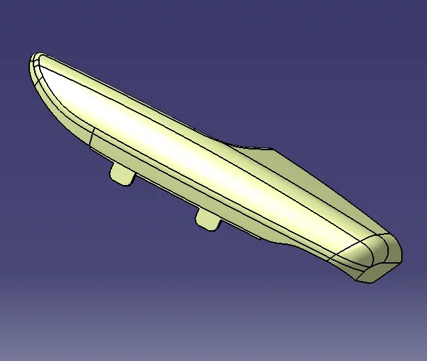
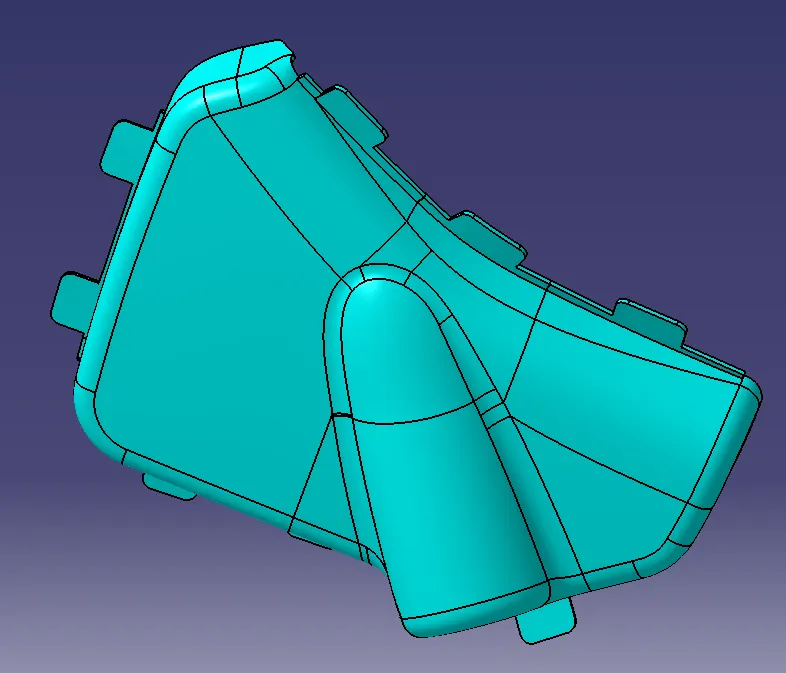
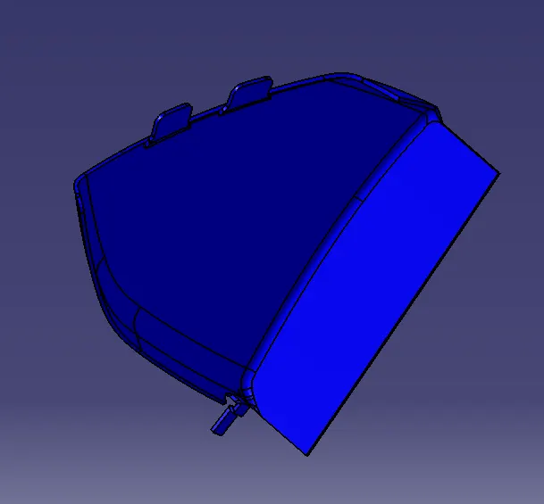
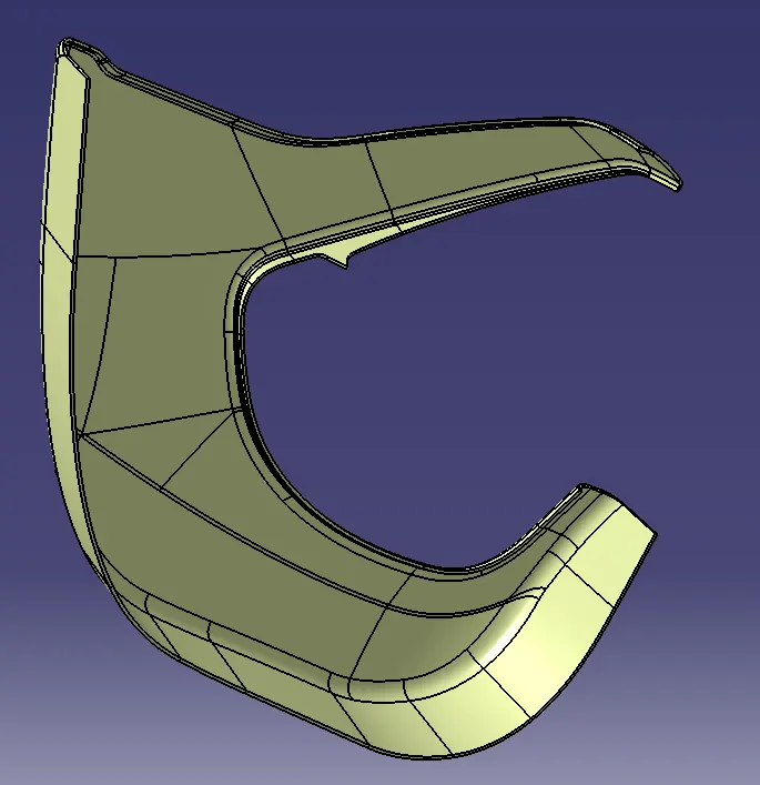
- Similarly, create the solid components for the remaining class A surfaces by creating class B and C surfaces as done above for the lower substrate of the door panel.
- Now the engineering features such as the heat stakes and dog houses are to be created on the class B side of the component. Constructions for the heat stakes and the dog houses are as shown below:
Heat stakes:
- The engineering features are to be created for the main component which holds the remaining components together i.e., the lower subtract of the door panel.
- To create a heat stake, create a circular sketch in the position sketch feature with a 7.5mm diameter.
- In generative shape design workbench, extrude the created sketch as shown below.
- Now using the thicken feature in the part workbench, thicken the heat stake towards the inner side of the surface up to 2mm.
- As the heat stakes are used for holding another component with the help of the flange features, holes are to be created on the flanges of another component.
- Offset the surface with which the heat stakes are created towards the outer sides maintaining the clearance of 0.5mm.
- Using the solid split option in the part workbench create the hole provisions on the flange surface.
- Draft the heat stake up to 0.3 degrees and the hole up to 0.5 degrees as per the clearance required.
- Create the duplicate heat stakes by copying and pasting the heat stake part body in the tree structure and translate them as required for attaching the remaining components. The distance between the heat stakes should be up to 60mm.
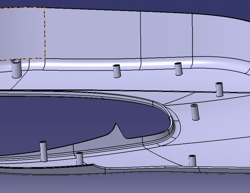
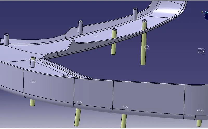
Dog Houses:
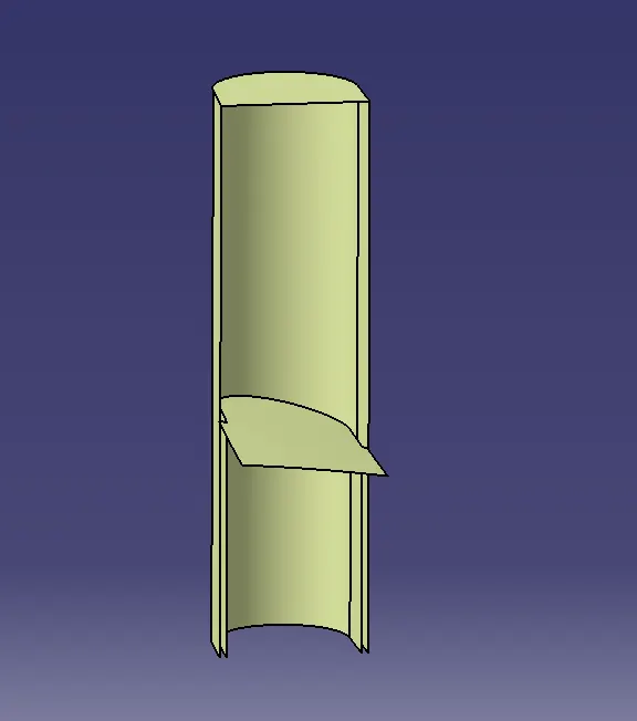
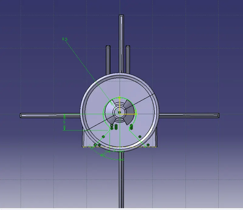
- The dog houses are created for mounting the push pins.
- Create the dog house outer sketch using the position sketch workbench.
- Pad the sketch up to the height of the lower substrate door panel walls.
- Draft the outer walls of the padded component at 0.5 degrees.
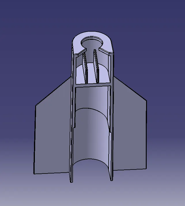
- The dog house should be hollow inside. To extract the outer walls of the padded surface using the surface feature.
- Offset the extracted surface towards the inner side up to 2mm.
- Create the solid split to the dog house using the offset surface as shown below.
- Now create the inner ribs by creating a surface inside the dog house and thickening it in the part workbench up to 1mm.
- Translate the dog houses as many required as done for the heat stakes.
- Now create an undercut for each dog house by extracting the surface below and offsetting it up to 6mm above. Create a shell structure using the surfaces as shown below and solid split the dog house as shown below.
- Create a hole provision as shown below such that a push pin can be easily assembled.
RIBS ARE PROVIDED ECONOMICAL STRENGTH OF THE MOULDING PARTS WITHOUT INCREASING WALL THICKNESS.
DESIGN ROOLES:
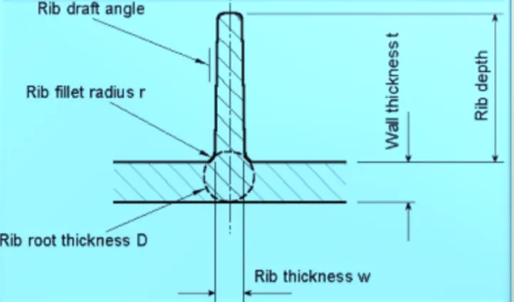
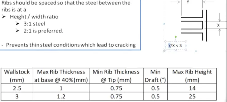
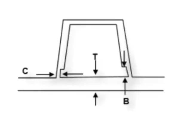
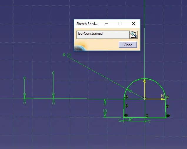
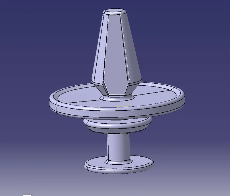
PUSHPIN CREATION
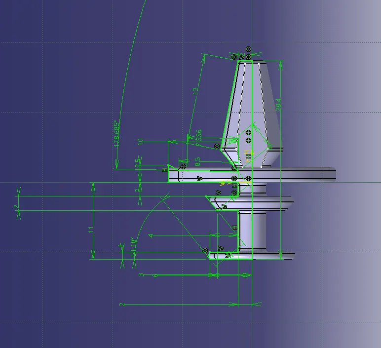
- The pushpins are the attachment to the Dog Houses which helps to join with the other component features by locking it.
- To create a pushpin, draw a sketch as an outer line of the pushpin on the side view as shown below.
- Using shat rotate on the part workbench rotate the sketch 360 degrees referring to the axis.
- Adjust the created pushpin into the dog house upper opening as shown below.
- Create a cut inside the pushpin as shown below using position sketcher and pocket operation.
- Now create duplicates for the pushpins as done for the heat stakes and translate them for each dog house as shown below.
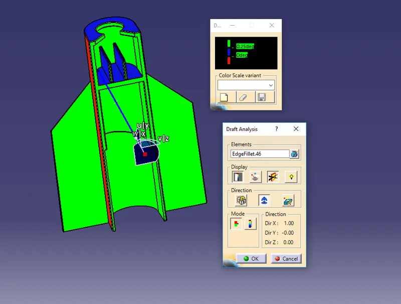
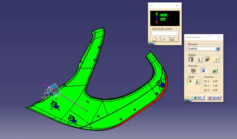
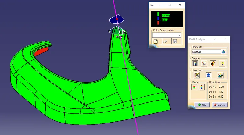
DRAFT ANALYSIS:
1.Open the Draft analysis by Insert > Analysis > Feature Draft Analysis.
2.Select the Compass - Direction in Draft Analysis and align it to the Tooling Axis and then lock it
3.After locking it a cross symbol will occur at the pointer, select the surface and the surface selected turns into green.
4.In Draft Analysis 2 box, select the green column to change the draft angle to 0.25 degrees.
5.The color should be green in color.
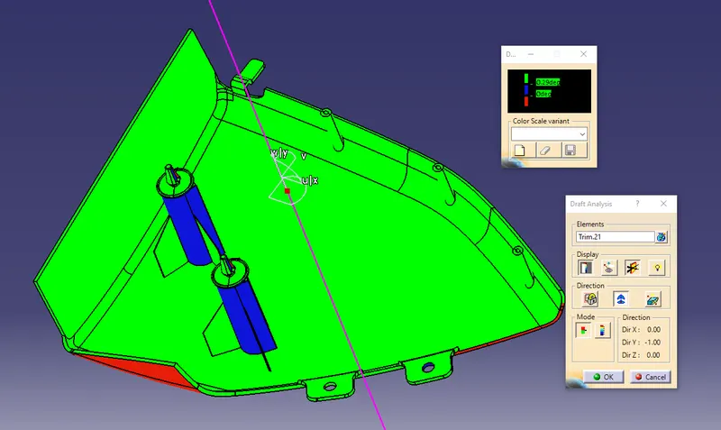
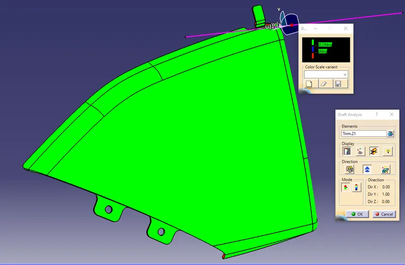
DRAFT ANALYSIS IS VERY IMPORTANT TO DESIGN THE PLASTIC COMPONENTS BECAUSE WHEN WE MAKING A PART THAT WILL BEY MOLDED THE ANALYSIS WILL VERIFY THAT ALL SURFACES ARE FAVOURABLE FOR BEING PULLED FROM CAVITY. IT MAY ALSO HEIGHLET THE TROUBLE AREAS ALSO.
DOG HOUSE:
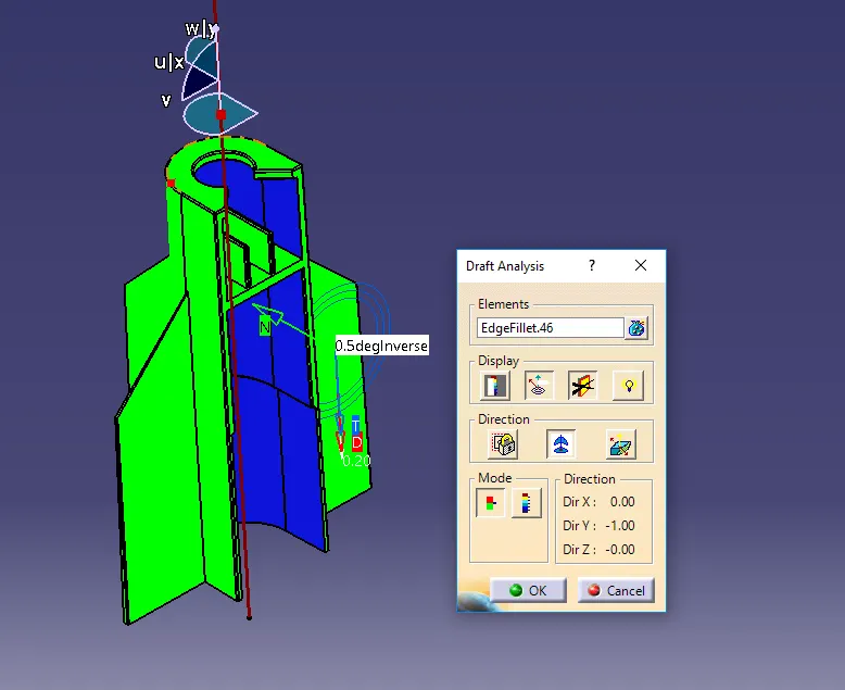
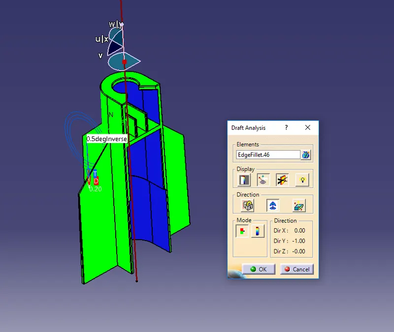
DRAFT ANGLE ON THE DOG HOUSE IS 0.5 DEGREES
IN THIS ANALYSIS COLOR VARIANT GREEN IS ABOVE 2.5, BLUE IS 0 TO 0.25
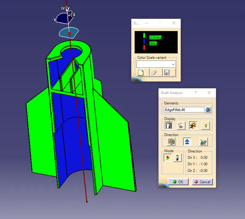
DRAFT ANALYSIS IN SLIDING DIRECTION:
LOWER SUBSTRATE:
ARMREST 1:
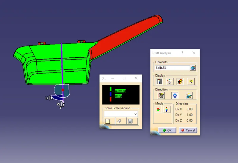
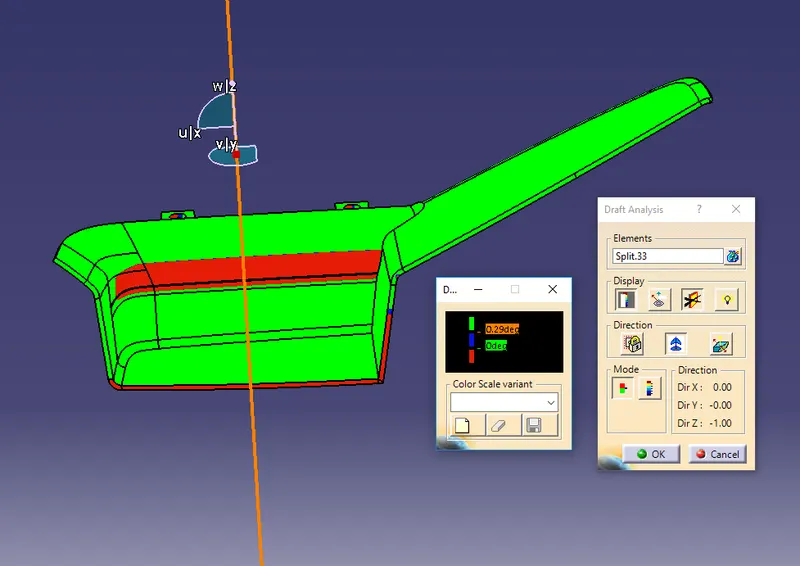
ANALYSIS THROUGH SLIDER DIRECTION DRAFT ANALYSIS ALONG WITH TOOLING AXIS
ARMREST 2:
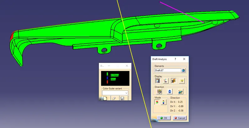
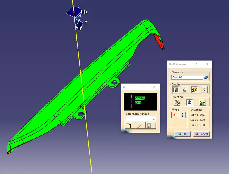
DRAFT ANALYSIS ALONG WITH SLIDER AXIS DRAFT ANALYSIS ALONG WITH TOOLING AXIS
MAP POCKET 1:
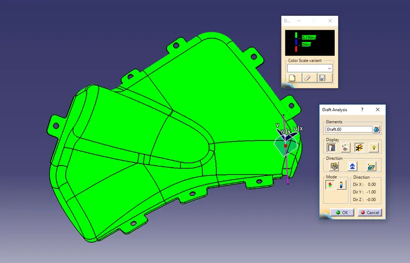
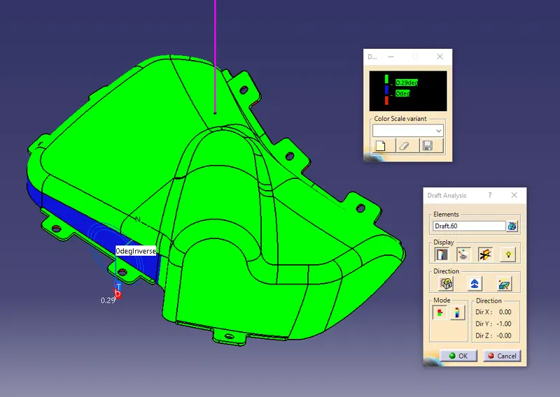
COLOR VARIANT BLUE IS 0 DEGREE WITH TOOLING AXIS GREEN COLOR SHOULD ABOVE 2.9 DEGREE SHOWS IN DRAFT ANALYSIS.
MAP POCKET2:
CONCLUSION:
THUS THE CAR INTERIOR DOOR TRIM IS DESIGNED USING THE GIVEN CLASS A AND MASTER SECTIONS.
CLASS B SURFACE CREATED WITH RESPECT CLASS A.
FLANGES ARE CREATED WITH RESPECT TO MASTER SECTIONS
CLASS C CREATED WITH RESPECTED TO TOOLING AXIS AND CLASS A.
FEATURES OF THE COMPONENT SUCH LIKE DOGHOUSE AND HEATSTAKES RESPECT WITH DESIGN RULES
WOLD TAKE DRAFT ANGLE OF THE COMPONENT IS 3 DEGREES, 0.5 degrees AT FEATURES
DRAFT ANALYSIS IS VERY IMPORTANT TO DESIGN THE PLASTIC COMPONENTS BECAUSE WHEN WE MAKING A PART THAT WILL BEY MOLDED THE ANALYSIS WILL VERIFY THAT ALL SURFACES ARE FAVOURABLE FOR BEING PULLED FROM CAVITY. IT MAY ALSO HEIGHLET THE TROUBLE AREAS ALSO.