FRONTAL CRASH ANALYSIS-BIW
FRONTAL CRASH ANALYSIS-BIW
AIM: To perform a frontal crash Analysis of the givein model.
OBJECTIVE:
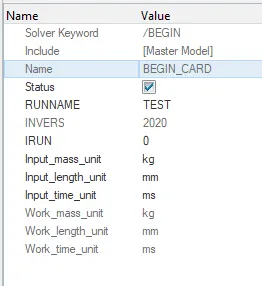
- Check unit system and either follow [Kg mm ms].
- Create an appropriate interface, friction 0.2, and recommended parameters.
- Make sure of no penetrations and intersections.
- Correct rigid bodies if any issues.
- Create rigid wall with friction 0.1.
- Compare the model weight with the full-scale 300k nodes model and use added masses to reach target weight 700kg while getting CG about the required range.
- Initial velocity 35 mph.
- Use model checker to ensure good quality.
- Time-step :0.5 to 0.1 microseconds.
- Run 80 ms.
ABSTRACT:
- Import the BIW model in hypermesh radious profile
- Case setup of the model
- Clear the errors using with hypercrash
- Run the simulation
- Create animation file from Hyperview
- Plot the curves in Hyper graph
- Observe the Results
PROCEDURE:
- Import the model in Hypermesh radious profile.
- Check unit system and follow [Kg mm ms].
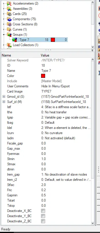
- Create interface TYPE 7.
- Interface TYPE7 is a multi-usage impact interface, modeling contact between a master surface and a group of slave nodes. It is also possible to consider heat transfer and heat friction.
- Go to Model > Create group Name as type7.
- give the friction value o.2. And also give standard parameters.
- Like inacti=6 - Gap is variable with time, but initial gap is adjusted as (the node is slightly depenetrated)
- I del=2 - Node and segment deletion flag
- I stf=4 - Interface stiffness is the minimum of the master and slave stiffness
- I gap=2 - Variable gap + gap scale correction of the computed gap.
- I form=2 - Stiffness (incremental) formulation.
- Gap min=0.5 - Minimum gap for impact activation.
- St min=1 - Minimum stiffness
- check penetrations
Tools > click on CHECK PENETRATION > SLECT GROUPS >tick on TYPE 7 > hit on CHECK
- Model checker
TOOLS > MODEL CHECKER > RUN THE ERRORS
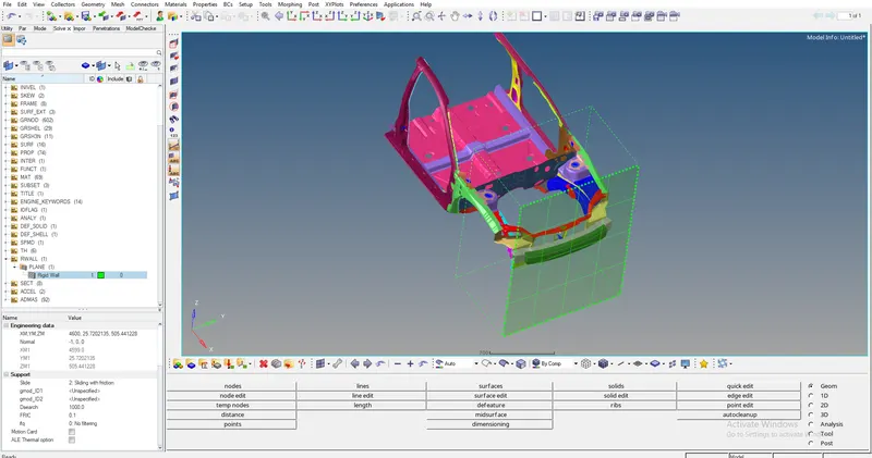
- Create rigid wall with friction 0.1.
go to SOLVER > CREATE > R WALL > CREATE
- Give the vslues in normsl x=-1,y=0,z=0 and D search value is1000.
- Increase the xm value for required gap between the bumper and rigid wall.
- Add masess reach to 700 kg
- while getting CG about the required range
go to SOLVER > CREATE >ADD MASS
- Select the nodes add the required mass .check mass details
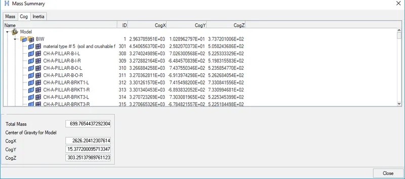
- To find, the center of gravity for the model gives the x,y,z values in nodes
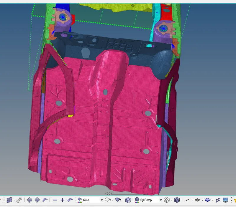
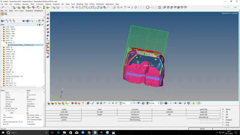
- Give the initial velocity 35mph for the car in x direction.
- Change the mph to mm/ms 35mph=15.64mm/ms
- create inivel card.
go to SOLVER > CREATE > BOUNDARY CONDITIONS > INIVEL
- In inivel card give the veleocity 15.64 in x direction
- create groud id select the all node and create initial velocity of the car
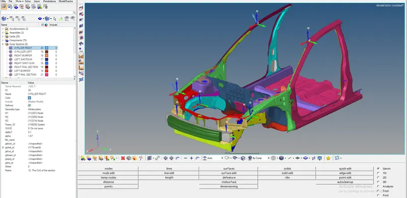
- Create Sectional force in the rails at location of indicated node 174247.
- Axial force received on the rails from bumper.
- Shotgun cross sectional forces.
- A pillar cross section And bumper
- create a cross section for left and right side of the car.
- for create cross section of the right side a_piller of the car.
- first create frame on the A_piller.Go solver and create frame click on move option and select the nodes on apiller and create freame.
SOLVER > FRAME > MOVE >CREATE
- After that create cross section. go to solver and create section name as apiller select the N1,N2,N3.Nodes and call the frame in frame id tahn select the elements proceed
- give the `Deltat`=0.1 and `alpha`=1.67
Solver > create >sect
- Follow the above procedure and create the all cross sections similarly.
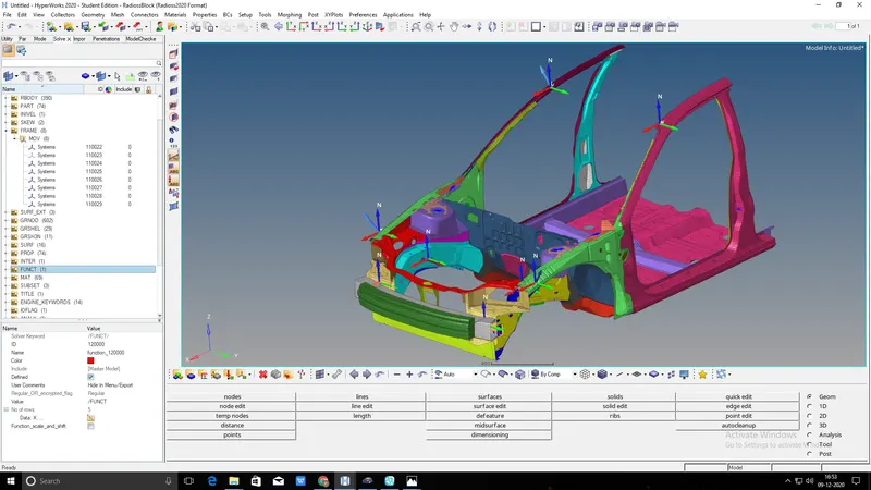
- Acceleration curve received on the accelerometer at base of B pillar (on B pillar rocker).
- craete accelerometere on B piller of the car left and eight sides
- go to solver and create the accelerometer and select the node on the b piller and give the fcut value is 1.65mse-1
SOLVER >CREATE > ACCELEROMETER
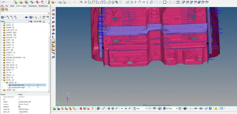
- Create Intrusions on the dash wall 66695,66244.
- first create the skew at opposite from the mentoined element.
- than go to out put block and create itrusion and select the node and select the skew id
model > output block >create intrusion
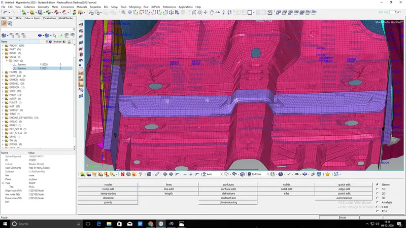
- go out put block and create cross section and click on entity ids and selectthe all cross section.
- go to model in hypermesh and click on cards and select the Engine run give t stop value is 80
- and select the Anim dt give the time step value is 0.4
- than run the simulation.
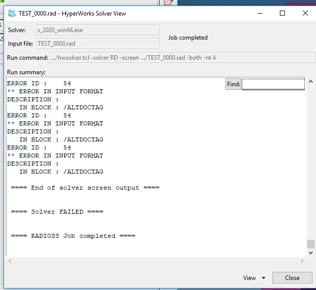
- Smulation didnt run .shows the errors.
RECTIFY THE ERRORS:
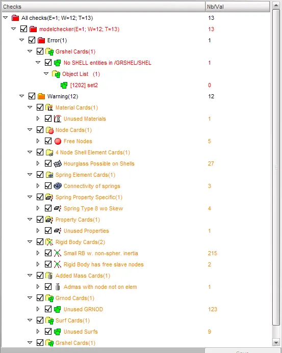
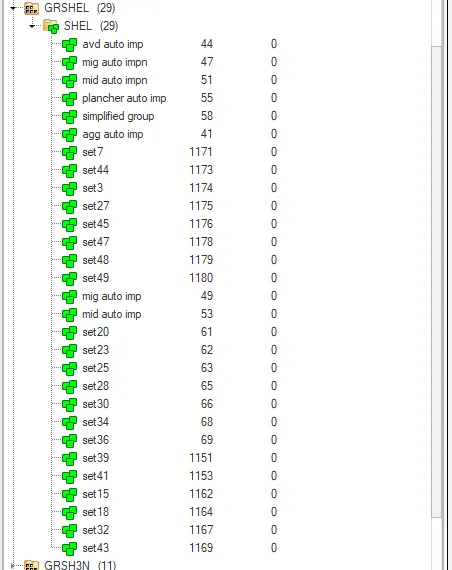
- GR SHELL:Find the 3 errors in the simulation these 3 comess from 3 empty sets there tn sets .
- Export the model in new folder and Import in Hypercrash rfind the errors and rectify some errors
- go to solver and click on GRshell and check the empty sets manually delete the 3 empty sets rectify the ERROR 534.
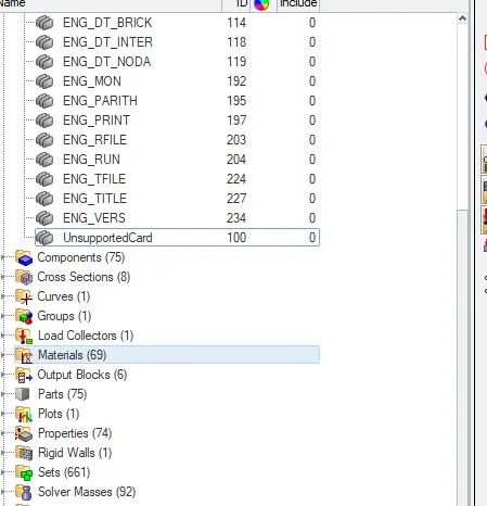
- in the model unsupported card is there.deleted the unsupported
- Ground id: create empty sets also creates when add mass in ground id.rectify the errors with using hypercrash.
- Unsupported card :on import the few radious cards not supported by engineering solutions are written to the unsupported cardsThis panel can be accesed from thethe menu bar by setup>control caeds. the unsupported card exported with reamaining model.unsupported card stored astext and pointers are not considered
LEARNING OUTCOMES:
- From this model learning lot of things mainly clear the Errors while doing simulations.
- create intrusions,cross sections and initial velocity.
- knowing the type 7 parameters.
- This challange teaches me something new.
RESULT: Analysis the the frontal crash and plot the curves.
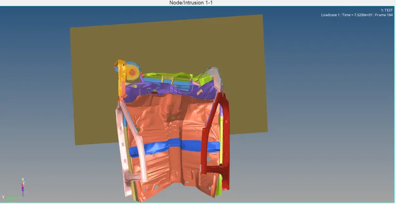
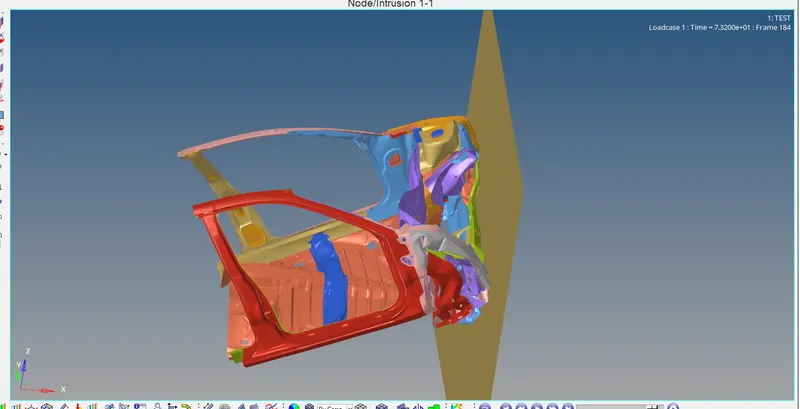
CRASH ANIMATION: The deformation occures more in right side of the car compare with left side.Raise the front of the car during the crash. might be result of the mass balencing we have done in this model.
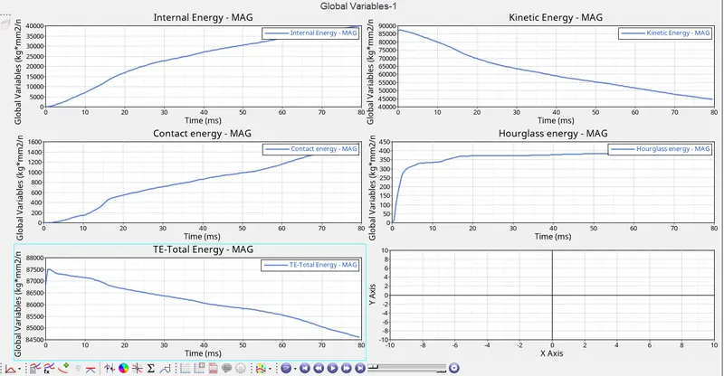
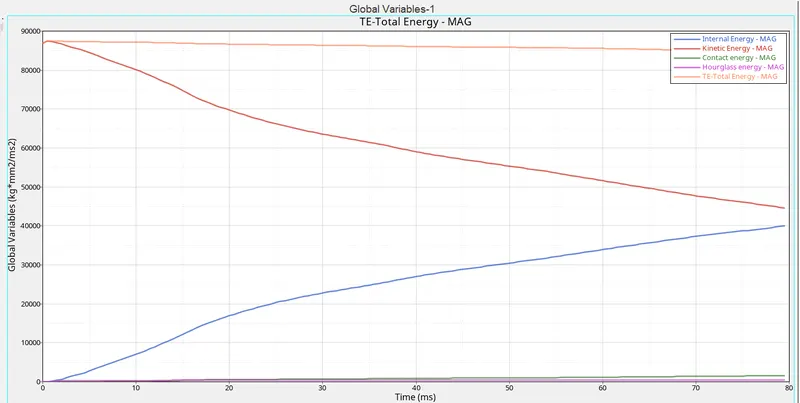
ENERGY PLOTS: This plots shows the K.E is decrease and increase the internal energy after the occurance of the impact.the total energy has stayed nearly constantthrough out the run.hourglass energy is very negligeble valiue. the contact energy can be seen to have icrease across the run time with increasing amount of deformations impacted on the model.
SECTIONAL FORCE ON THE RAIL: The forces on both sides increase as impact takes place and reaches the peak valuea of right rail section is15.19KN and the left rail section is12.53KN.the forces are decreasing until the end of the simulation.


fig: peak values of left and right rail sections
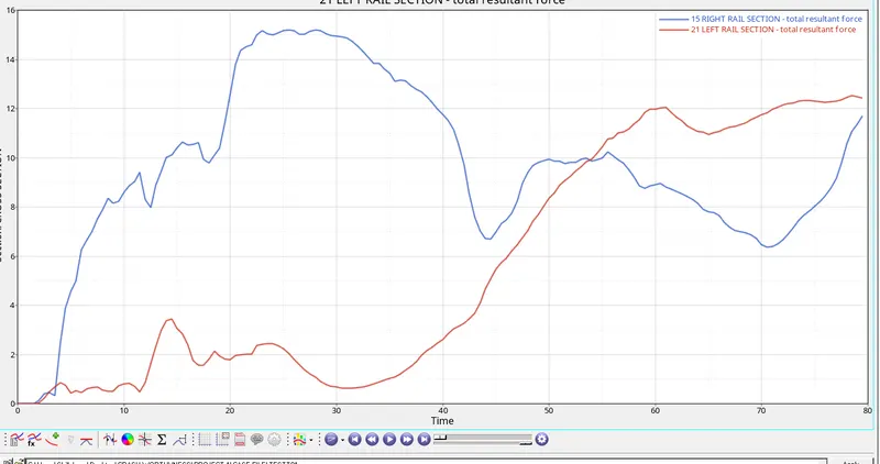
pic:graph of rail sections
SECTIONAL FORCES OF THE PILLERS: A Peak force recorded in the right side rail section is28.5KN AND LEFT RAIL SECTION IS 40.5 The hiher force applied on the left side A PILLER.


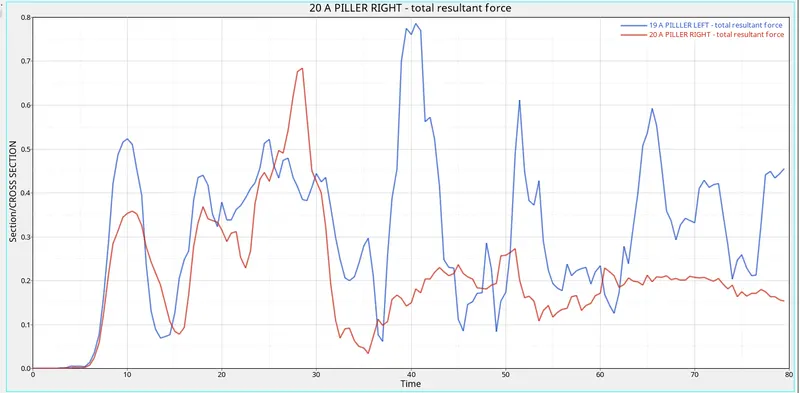
PIC: GRAPH of the left and right pillar sections.
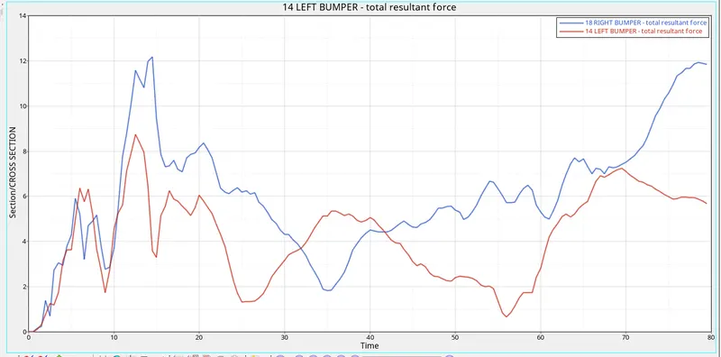
SECTIONAL FORCES ON THE BUMPER: In this section recorded high values at the baganing and decrese the force as the run progress.high value recorded in right bumper 12.18KN. and 8.7KN Recorded on the left side bumper.


PICS: Peak values of the bimper
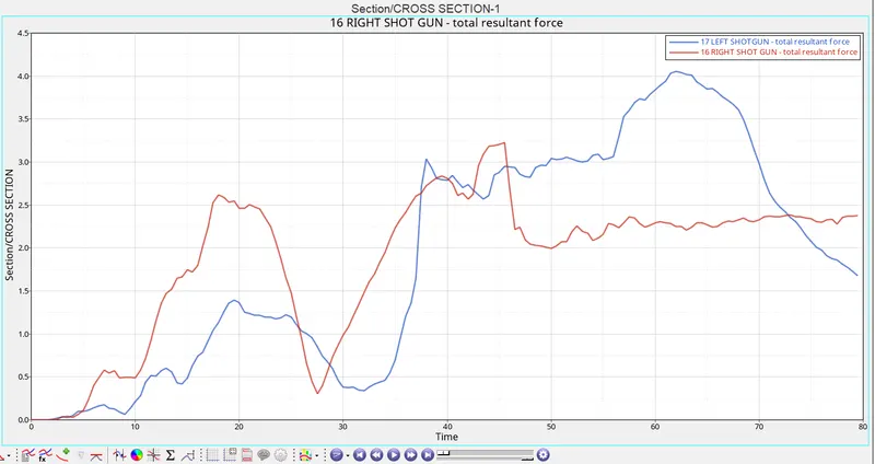
SECTIONAL FORCES ON SHOTGUN: It's similar to the A pillar sectional force. shotgun sectional forces also indicate large force transfer to the left side section.the peak value of the left side section is 62KN. and 45KN Force transfer to the right side shotgun.


pics: peak values of the shot gun
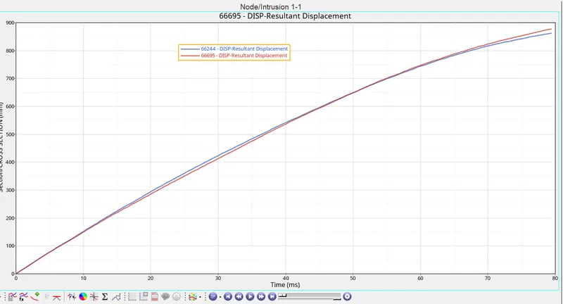
INTRUSION OF NODES 66695 and66244: The resultant elongation of the intusion is the value of elongation at the end of the simulation will give the intrusion measurements for both nodes during the run time.


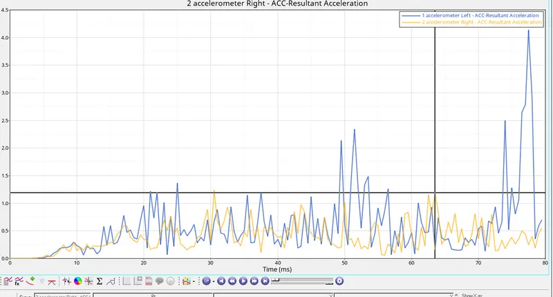
ACCELARATIONS MEASURED BY THE ACCELEROMETER: The plots shows the acceleration values recorded by the accelorometer placed at the rockers armsat thebottom of the B pillers.The accelarator on the left rockers has recorded more variationsand peaks as aresult of moredeformations on the left side.the right side accelerometer has recorded lower acceleration variations.
OUT FILE:
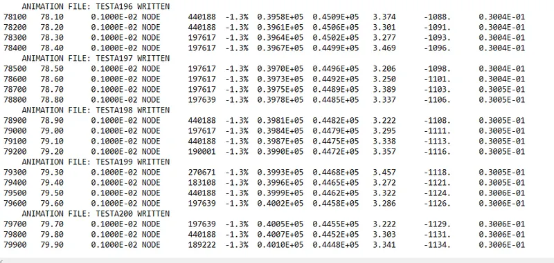
ENERGY ERROR= 1.3% MASS ERROR=3%
CONCLUSION:
- The solver deck was setup as per istructions.
- all out put requests were placed
- the simulation was runn successfullywith acceptable energy error=1.3% and mass error=3%
- the right side of the car BIW model more deformations compared to the left side
- all the sectional forces were ploted
- intrusions were measured using nodes 66695 and66244
- accelerometers created on the rockers