Week-7 Challenge: DC Motor Control
DC MOTOR CONTROL
BJT H-bridge:
- An H-bridge is a simple circuit that lets you control a DC motor to go backward or forward.
- The Bipolar Junction Transistor (BJT) when used for power switching applications, operates as an IGBT
- The H-bridge consists of four BJT/Diode pairs
Here’s the concept of the H-bridge:
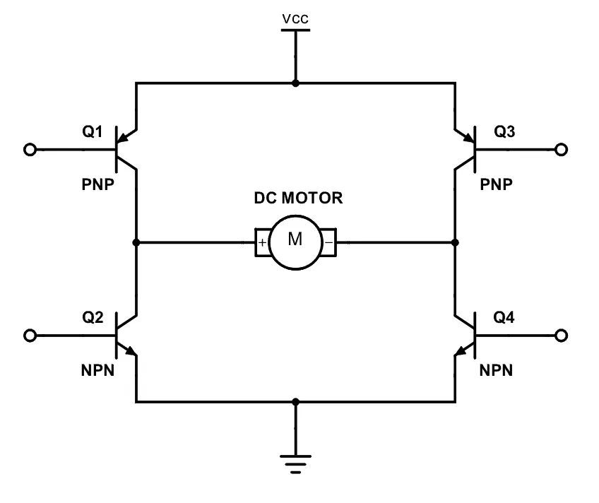
- A DC motor spins either backward or forward, depending on how you connect the plus and the minus.
- If you close switches 1 and 4, you have plus connected to the left side of the motor and minus to the other side. And the motor will start spinning in one direction.
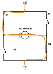
- If you instead close switch 2 and 3, you have plus connected to the right side and minus to the left side. And the motor spins in the opposite direct
CHOPPER:
- a chopper circuit is any of numerous types of electronic switching devices and circuits used in power control and signal applications. A chopper is a device that converts fixed DC input to a variable DC output voltage directly.
- It is basically a high-speed ON/OFF semiconductor switch.
- The average value of output DC voltage may be less than or higher than the input DC voltage source
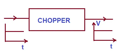
- there are two types of chopper: Step-up and Step-down Chopper.
- A chopper whose average value of DC output voltage is more than the fixed DC input voltage is called Step-up Chopper.
- While a chopper whose average value of DC output voltage is less than the DC input voltage is called a Step-down chopper.
SPEED CONTROL OF DC MOTOR Using BJT H-Bridge:
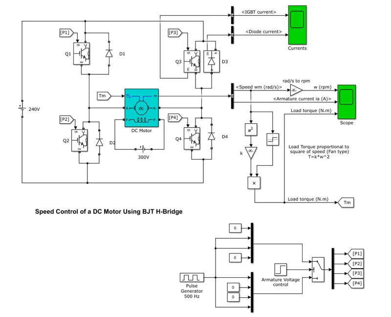
- Open the model in MAT LAB HELP. Speed control of DC MOTOR Using BJT H-Bridge.
- The model is opened in the Simulink workspace.
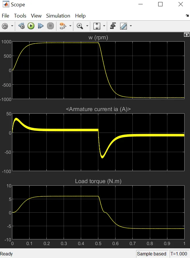
- Run the model as it is. And observe the armature current shoot-up from the scope results.
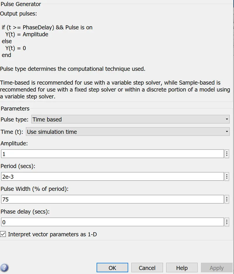
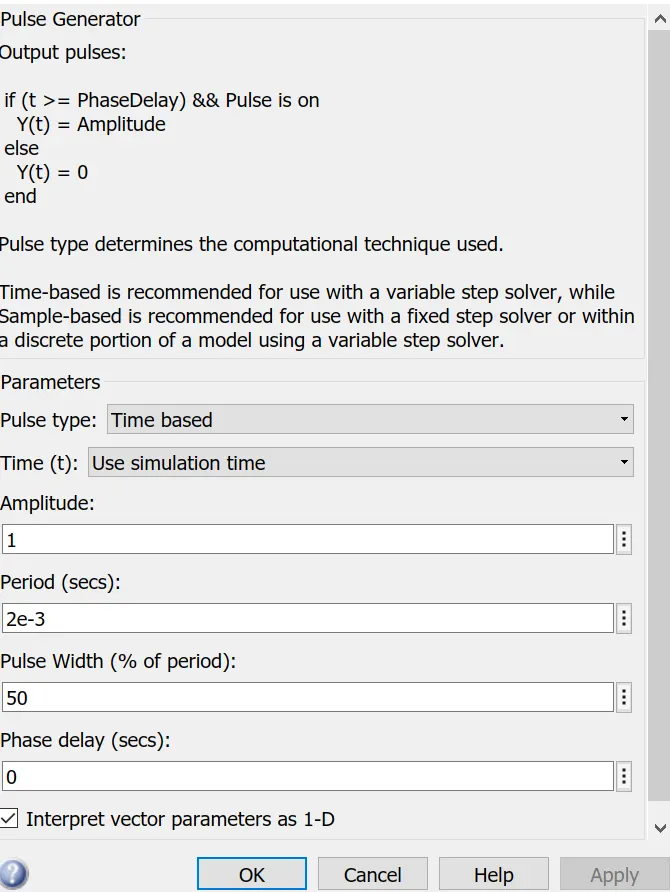
- Check the scope results at pulse with 50% and 75%.
- At 75%
At 50%:
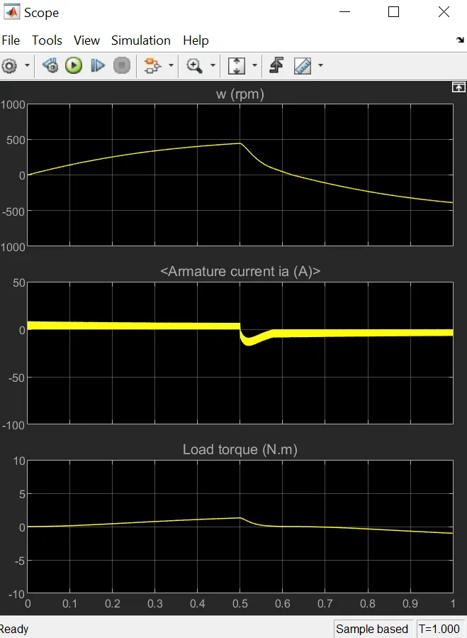
- AS PULSE WIDTH DECREASES THE STEP VALUE OF THE ARMATURE CURRENT AND TORQUE ALSO DECREASE.
Four-Quadrant Chopper DC Drive (DC7) block:
The Four-Quadrant Chopper DC Drive (DC7) block represents a four-quadrant, DC-supplied, chopper drive for DC motors.
The 200 HP DC motor is separately excited with a constant 150 V DC field voltage source. The armature voltage is provided by an IGBT converter controlled by two PI regulators. The converter is fed by a 515 V DC bus obtained by rectification of a 380 V AC 50 Hz voltage source. In order to limit the DC bus voltage during dynamic braking mode, a braking chopper has been added between the diode rectifier and the DC7 block.
The first regulator is a speed regulator, followed by a current regulator. The speed regulator outputs the armature current reference (in p.u.) used by the current controller in order to obtain the electromagnetic torque needed to reach the desired speed. The speed reference change rate follows acceleration and deceleration ramps in order to avoid sudden reference changes that could cause armature over-current and destabilize the system. The current regulator controls the armature current by computing the appropriate duty ratios of the 5 kHz pulses of the four IGBT devices (Pulse Width Modulation). For proper system behaviour, the instantaneous pulse values of IGBT devices 1 and 4 are opposite to those of IGBT devices 2 and 3. This generates the average armature voltage needed to obtain the desired armature current. In order to limit the amplitude of the current oscillations, a smoothing inductance is placed in series with the armature circuit.
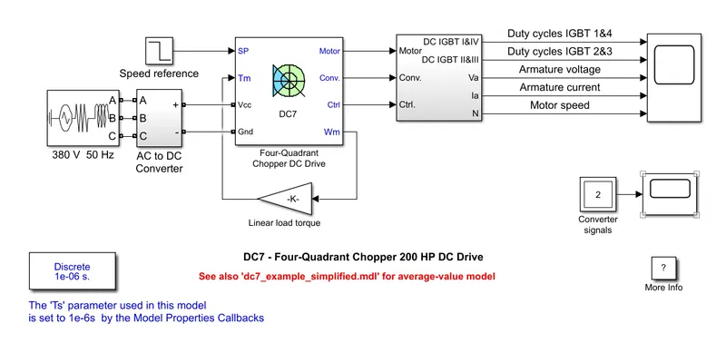
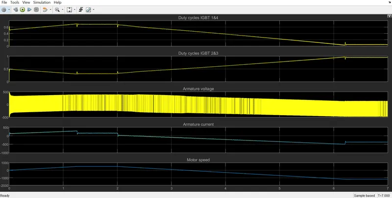
| Bjt-H Bridge Model | DC-7 Drive |
|
1.Operates only forward and reverse motoring 2.Closed-loop chopper (takes feedback from the output change the input) 3.Armature current oscillations are reduced by something inductance connected by series with the armature circuit. 4.pi controllers are used for dynamic control of pulse width 5. continuous computation. |
1.Operates in all quadrants. (forward, reverse, breaking motoring) 2.open-loop chopper. 3. Need lower duty cycles for reducing armature current ripples 4. we provide a fixed value of pulse width for simulation 5. discrete computation required for the model. |
3. 2- QUADRANT CHOPPER
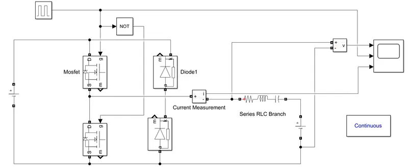
The Two-Quadrant Chopper block represents a two-quadrant controlled chopper for converting a fixed DC input to a variable DC output. The block contains two switching devices. Options for the type of switching devices are GTO — Gate turn-off thyristor.
The Two-Quadrant Chopper DC Drive (DC6) block represents a two-quadrant, DC-supplied, chopper (or DC-DC PWM converter) drive for DC motors. This drive features closed-loop speed control with a two-quadrant operation. The speed control loop outputs the reference armature current of the machine. Using a PI current controller, the chopper duty cycle corresponding to the commanded armature current is derived. This duty cycle is then compared with a sawtooth carrier signal to obtain the required PWM signals for the chopper.
4.BRUSHLESS DC MOTOR:
Brushless DC motor systems combine compact yet powerful brushless DC motors and high-performance drivers to offer excellent energy savings and speed stability as well as a wide speed control range. With brushless DC motors, you can downsize your application as the motors have slim bodies and provide high power due to permanent magnets being used in the rotor.
Oriental Motor offers a wide range of brushless DC motor products featuring:
- Output Power from 15 W (1/50 HP) up to 400 W (1/2 HP)
- Parallel Shaft, Right-Angle Shaft, and Flat Hollow Shaft Gear option.
H1 Food-Grade Grease-Compatible Gear Motors available
- Electromagnetic Brake options
- AC or DC Input Drivers
CONSTRUCTION:
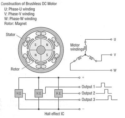
Brushless DC motors use permanent magnets in the rotor of three-phase motors. In addition, on the inside of the stator, there is a built-in hall effect IC (magnetic sensor) that detects magnetic field changes with the permanent magnets, The feedback signals from the Hall effect IC of the motor are compared with the setting speed by the driver and the motor speed is adjusted continuously.
The brushless DC motor features a coil that is star-wired (Y-wired) with three phases: U, V, and W and is located in the stator, and the rotor is made of magnets magnetized in a multi-pole configuration as shown in Fig. 1.
Inside the stator, three hall ICs are arranged as magnetic elements so that the phase difference of the output signal from each hall IC will be 120 degrees apart for every rotation of the rotor.